


S/M No. : FR630NT010
Service Manual
Refrigerator
Model: FR-630NT/NB
FR-662NT/NB
FR-700NT/NB
DAEWOO ELECTRONICS CO., LTD.
http : //svc.dwe.co.kr |
Nov. 1999 |

SAFETY AND PRECAUTIONS
1)For starters, be sure to check any chances of the leakage of electricity.
2)You could handle a part in the vicinity of electricity after unplugging.
3)You should put on rubber gloves to prevent an electric shock on operation test.
4)Make sure the rated current, voltage, capacity before using an instrument.
5)Keep your wet hands away from the metal goods in the freezer compartment not to be frostbitten.
6)Be careful not to let water to permeate the electric part in the machine room.
7)With the door open during your repair, you might be hurt by that door.
8)You should give a tilt to the refrigerator for your safe after removing the breakable goods inside the refrigerator.
9)You'd better use gloves if you fix it up around the evaporator.
TABLE OF CONTENTS |
|
EXTERNAL VIEWS ............................................................................................................................. |
2 |
1. EXTERNAL SIZE........................................................................................................................... |
2 |
2. NAME OF PARTS ......................................................................................................................... |
2 |
SPECIFICATIONS ............................................................................................................................... |
3 |
1. OUTLINE ....................................................................................................................................... |
3 |
2. ELECTRIC PARTS........................................................................................................................ |
3 |
3. POWER CORD ............................................................................................................................. |
8 |
4. DOOR COLOR .............................................................................................................................. |
9 |
OPERATION AND FUCTIOLNS.......................................................................................................... |
10 |
DIAGRAM ............................................................................................................................................ |
17 |
1. WIRING DIAGRAM ....................................................................................................................... |
17 |
2. RATICAL WIRING DIAGRAM ....................................................................................................... |
17 |
3. CIRCUIT DIAGRAM ...................................................................................................................... |
18 |
4. AIR FLOW DIAGRAM ................................................................................................................... |
18 |
5. REFRIGERANT CYCLE DIAGRAM .............................................................................................. |
19 |
DISASSEMBLY AND ASSEMBLY...................................................................................................... |
20 |
EXPLODED VIEW AND PARTS LIST................................................................................................. |
37 |
1. EXPLODED VIEW......................................................................................................................... |
37 |
2. TOTAL PARTS LIST ..................................................................................................................... |
38 |
3. MACHINE ROOM EXPLODED VIEW AND PARTS LIST............................................................. |
42 |
1

EXTERNAL VIEWS
1. EXTERNAL SIZE
|
|
|
|
|
|
|
|
|
|
21.7 |
|
|
|
|
|
|
|
|
|
|
|
|
|
|
|
|
24 |
|
|
|
|
|
|
|
|
|
|
810 |
|
|
|
|
523 |
|
|
|
|
|
|
|
|
|
|
|
|
|
|
|
|
|
|
|
|
|
|||
|
|
|
|
|
|
|
|
|
|
|
|
|
|
|
|
|
|
|
|
|
|
|
|
|
|
|
|
|
|
|
|
|
|
|
|
|
|
|
|
|
|
|
A |
54 |
|
|
|
|
|
|
|
|
|
|
|
|
|
|
|
|
|
|
|
|
|
||
|
|
|
|
|
|
|
|
|
|
|
|
|
|
|
||
|
|
|
|
|
|
|
|
|
|
17.4 |
|
|
|
|
|
|
|
|
|
|
|
|
|
|
|
|
|
|
|
|
|
|
|
|
|
|
|
|
|
|
|
|
|
|
|
|
|
|
|
|
|
|
|
|
|
|
|
|
|
|
|
|
|
|
|
|
|
|
|
|
|
|
|
|
|
|
|
|
|
|
|
|
|
|
|
|
|
|
|
|
|
|
|
|
|
|
|
|
|
|
|
|
|
|
|
|
|
|
|
|
|
1041 |
|
|
|
|
|
|
|
|
|
|
|
|
|
|
|
|
|
|
|
|
|
|
|
|
|
|
|
|
|
|
|
818.6 |
113.4 |
|
|
|
|
|
|
|
|
|
|
|
|
|
|
|
|
|
|||||||
|
|
|
|
|
|
|
|
|
|
|
|
|
|
|
|
|
|
|
|
|
|
|
|
|
|
|
|
|
|
|
|
|
|
|
|
|
|
|
|
|
|
|
|
|
|
|
|
|
|
|
24
810
|
|
|
|
|
|
|
|
|
|
|
|
|
|
|
|
|
|
|
|
|
|
|
|
|
|
|
|
|
|
|
|
|
|
|
|
|
|
|
|
|
|
|
|
|
|
|
|
|
|
|
|
|
|
|
|
|
|
|
|
|
|
|
|
|
|
|
|
|
|
|
|
|
|
|
|
|
|
|
|
|
|
|
|
|
|
|
|
|
|
|
|
|
|
|
|
|
|
|
|
|
|
|
|
|
|
|
|
|
|
|
|
|
|
|
|
|
|
|
|
|
|
|
|
|
|
|
|
|
|
|
|
|
|
|
|
|
|
|
|
|
|
|
|
|
|
|
|
|
|
|
|
|
|
|
|
|
|
|
|
|
|
|
|
|
|
|
|
|
|
|
|
|
|
|
|
|
|
|
|
|
|
|
|
|
|
|
|
|
|
|
|
|
|
|
|
|
|
|
|
|
|
|
|
|
|
|
|
|
|
|
|
|
|
|
|
762 |
|
|
|
24 |
|
|
|
|
|
|
|
|
|||
|
|
|
|
|
|||
27 |
|
|
|
|
|
|
|
|
|
|
|
|
|
|
|
|
|
|
|
|
|
|
35 |
|
62 |
|
|
|
|
|
|
|
|
|||||
|
|
|
|
|
|
|
|
|
|
|
|
|
|
|
|
|
|
|
|
|
|
|
|
|
|
|
|
|
|
|
||||||||
|
|
|
|
|
|
|
|
|
|
|
|
|
|
|
|
|
|
|
|
|
|
|
|
|
|
|
|
|
|
|
|
|
|
|
|
|
|
|
|
|
601 |
|
|
|
|
|
|
|
|
|
|
|
|
|
|
|
|
|
|
|
|
|
|
|
|
|
|
|
|
|
|
|
|
|
|
|
|
|
|
|
|
|
|
|
|
|
|
|
|
|
|
|
|
|
|
|
|
|
|
|
|
|
|
|
|
|
|
|
|
|
|
|
|
|
|
|
|
|
10.5 |
|
|
|
|
|
|
|
|
|
|
|
|
|
|
|
|
|
|
|
|
|
|
|
|
|
|
|
|
|
|
|
|
|
|
|
|
|
|
|
|
|
|
|
|
|
|
|
|
|
|
|
|
|
|
|
|
|
|
|
|
|
|
|
|
|
|
|
|
|
|
|
|
|
||
1791 |
|
|
|
|
|
|
|
|
|
|
|
|
|
|
|
|
|
|
|
|
|
|
|
|
|
|
|
|
|
|
|
|
|
|
|
|
|
|
|
|
|
|
|
|
|
|
|
|
|
|
|
|
|
|
|
|
|
|
|
|
|
|
|
|
|
|
|
|
|
|
|
|
|
|
|
|
|
|
|
|
|
|
|
|
|
|
|
|
|
|
|
|
|
|
|
|
|
|
|
|
|
|
|
|
|
|
|
|
|
|
|
|
|
|
|
|
|
1084 |
|
|
|
|
|
|
|
|
|
|
|
|
|
|
45 |
|
|
102 |
|
|
|
|
|
|
|
A |
25 |
||||||||||
|
|
95.5 |
|
|
|
|
|
|
|
|
|
|
|
|
|
|
|
|
|
|
|
|
|
|
|
|
|
|
|
|
|
|
|
|
|
53 |
|
|
|
|
|
|
|
|
|
|
|
|
|
|
|
|
|
|
|
|
|
|
|
|
|
|
|
|
|
|
|
|
|
|
|
|
|
|
|||
|
|
|
|
|
|
|
|
|
|
|
|
|
|
|
|
|
|
|
|
|
|
|
|
|
|
|
|
|
|
|
|
|
|
|
|
|||
|
|
|
|
|
|
|
|
|
|
|
|
|
|
|
|
|
|
|
|
|
|
|
|
|
|
|
|
|
|
|
|
|
|
|
|
|||
|
|
|
|
|
|
|
|
|
|
|
|
|
|
|
|
|
|
|
|
|
|
|
|
|
|
|
|
|
|
|
|
|
|
|
|
|
||
|
|
|
|
|
|
|
|
|
|
|
|
|
|
|
|
|
|
|
|
|
|
|
|
|
|
|
|
|
|
|
|
|
|
|
3 |
|
|
|
|
FR-630NT/NB |
FR-662NT/NB |
FR-700NT/NB |
A |
590 |
620 |
650 |
|
|
|
|
2. NAME OF PARTS
1  Freezer Compartment Lamp
2  Shelf Ffreezer
3  Case Icing
4  Guide Icing
5  Ice Box
6  Refrigerator Compartment Lamp
7  Cover Cubic Duct
8  Fresh Case
9  Shelf Refrigerator
10 Deodorant
11 Cover Vegetable
12 Case Vegetable(B)
13 Case Vegetable(A)
14 Guide Vegetable
15 Front Grille
16 Adjustable Foot
17 Freezer Pocket Top
18 Freezer Pocket Under
19 Egg Pocket
20 Egg Tray
21 Guide Bottle
22 Bottle Pocket
23 Multi Pocket
24 Multi Pocket
2
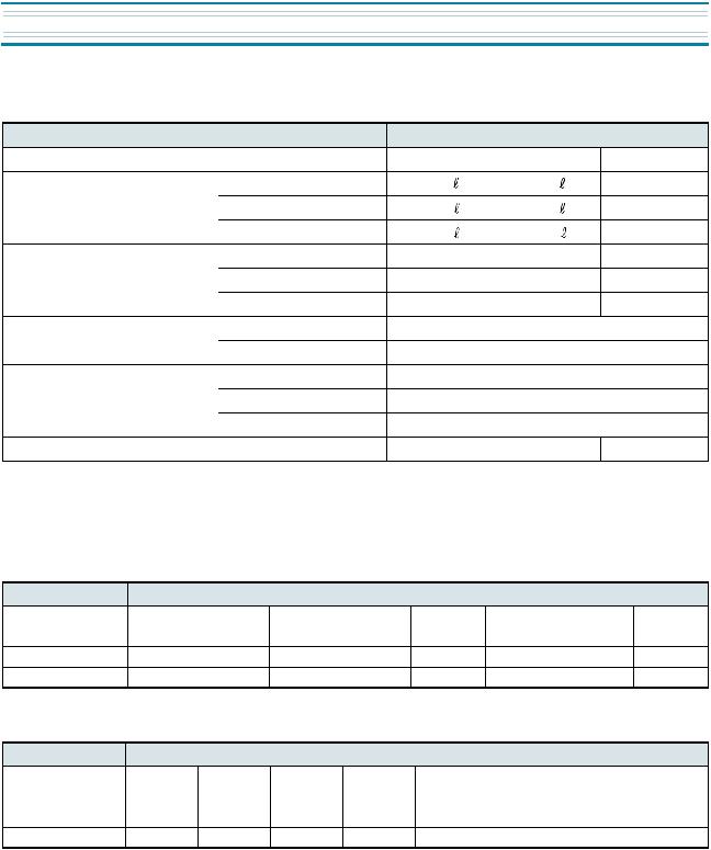
 SPECIFICATIONS
1. OUTLINE
DIVISION |
|
|
CONTENTS |
|
MODEL NAME |
|
FR-630NT/NB |
FR-662NT/NB |
FR-700NT/NB |
USABLE CAPACITY |
FREEZER |
138 |
147 |
156 l |
|
REFRIGERATOR |
366 |
377 |
398 l |
|
TOTAL |
504 |
524 |
554 l |
EXTERIOR DIMENSION |
WIDTH |
818 mm |
818 mm |
818 mm |
|
DEPTH |
752 mm |
782 mm |
812 mm |
|
HEIGHT |
1818 mm |
1818 mm |
1818 mm |
QUANTITY OF REFRIGERANT |
R12 |
|
170 g |
|
|
R134a |
|
140 g |
|
COOLING &CONTROL SYSTEM |
COOLING SYSTEM |
|
Fan Cooling System |
|
|
DEFROST SYSTEM |
Fin Evaporator Forced Defrosting System |
||
|
DEFORST CONTROL |
|
Automatic Start & Stop |
|
NET WEIGHT |
|
85 kg |
92 kg |
95 kg |
2.ELECTRIC PARTS
1)COMPRESSOR
REFRIGERANT |
|
|
|
|
R12 |
|
|
|
VOLTAGE ( V/HZ) |
100 /50,60 |
110 / 60 |
115,120/60 |
127/60 |
220/50 |
220 / 60 |
230 / 50 |
240 / 50 |
COMP MODEL |
X |
X |
X |
X |
SL28YE-5 |
PL23YH-4 |
SL28YE-5 |
SL28YE-5 |
PART CODE |
X |
X |
X |
X |
3954128A50 |
3956125G40 |
3954128A50 |
3954128A50 |
STARTING TYPE |
X |
X |
X |
X |
RSIR |
RSCR |
RSIR |
RSIR |
REFRIGERANT |
|
|
|
R134a |
|
|
|
|
VOLTAGE ( V/HZ) |
100 /50,60 |
110 / 60 |
115,120/60 |
127/60 |
220/50 |
220 / 60 |
230 / 50 |
240 / 50 |
COMP MODEL |
X |
HBL25YG-3 |
X |
HEL21YH-1 |
HPL26YH-5 |
X |
HPL26YH-5 |
HPL26YH-5 |
PART CODE |
X |
3952125R30 |
X |
3953121S10 |
3956126S50 |
X |
3956126S50 |
3956126S50 |
STARTING TYPE |
X |
CSR |
X |
RSCR |
RSCR |
X |
RSCR |
RSCR |
3

 SPECIFICATIONS
2) RELAY
REFRIGERANT |
|
|
|
|
R12 |
|
|
|
|
VOLTAGE ( V/HZ) |
100 /50,60 |
110 / 60 |
115,120/60 |
127/60 |
220/50 |
220 / 60 |
230 / 60 |
240 / 50 |
|
ASSY |
TYPE NAME |
X |
X |
X |
X |
276THBYY-52 |
181SHBYY-52 |
276THBYY-52 |
|
|
PART CODE |
X |
X |
X |
X |
3018119940 |
3018116610 |
3018119940 |
|
PTC |
RESIS-TANCE |
X |
X |
X |
X |
S220 |
S330 |
S220 |
|
|
PART CODE |
X |
X |
X |
X |
|
|
|
|
OVER LOAD |
PART CODE |
X |
X |
X |
X |
276THB |
181SHB |
276THB |
|
REFRIGERANT |
|
|
|
|
R134a |
|
|
|
|
VOLTAGE ( V/HZ) |
100 /50,60 |
110 / 60 |
115,120/60 |
127/60 |
220/50 |
220 / 60 |
230 / 60 |
240 / 50 |
|
ASSY |
TYPE NAME |
X |
783NHBZZ-52 |
X |
317NHBYF52 |
197NHBYY-52 |
X |
197NHBYY-52 |
197NHBYY-52 |
|
PART CODE |
X |
3018119390 |
X |
3018119950 |
3018119920 |
X |
3018119920 |
3018119920 |
PTC |
RESIS-TANCE |
X |
S220 |
X |
S068 |
S330 |
X |
S330 |
S330 |
|
PART CODE |
X |
|
X |
X |
|
X |
|
|
OVER LOAD |
PART CODE |
X |
783NHB |
X |
317NHB |
197NHB |
X |
197NHB |
197NHB |
3) STARTING CAPACITOR
REFRIGERANT |
|
|
|
|
R12 |
|
|
|
VOLTAGE ( V/HZ) |
100 /50,60 |
110 / 60 |
115,120/60 |
127/60 |
220/50 |
220 / 60 |
230 / 60 |
240 / 50 |
PART CODE |
X |
X |
X |
X |
X |
X |
X |
X |
RATED VOLTAGE |
X |
X |
X |
X |
X |
X |
X |
X |
RATED CAPACITANCE |
X |
X |
X |
X |
X |
X |
X |
X |
REFRIGERANT |
|
|
|
|
R134a |
|
|
|
VOLTAGE ( V/HZ) |
100 /50,60 |
110 / 60 |
115,120/60 |
127/60 |
220/50 |
220 / 60 |
230 / 60 |
240 / 50 |
PART CODE |
X |
3016400100 |
X |
X |
X |
X |
X |
X |
RATED VOLTAGE |
X |
200V |
X |
X |
X |
X |
X |
X |
RATED CAPACITANCE |
X |
100 |
X |
X |
X |
X |
X |
X |
4

SPECIFICATIONS 
4)RUNNING CAPACITOR
REFRIGERANT |
|
|
|
|
R12 |
|
|
|
VOLTAGE ( V/HZ) |
100 /50,60 |
110 / 60 |
115,120/60 |
127/60 |
220/50 |
220 / 60 |
230 / 60 |
240 / 50 |
PART CODE |
X |
X |
X |
X |
X |
400EL15110 |
X |
X |
RATED VOLTAGE |
X |
X |
X |
X |
X |
350V |
X |
X |
RATED CAPACITANCE |
X |
X |
X |
X |
X |
5 |
X |
X |
REFRIGERANT |
|
|
|
R134a |
|
|
|
|
VOLTAGE ( V/HZ) |
100 /50,60 |
110 / 60 |
115,120/60 |
127/60 |
220/50 |
220 / 60 |
230 / 60 |
240 / 50 |
PART CODE |
X |
3816800400 |
X |
400EL15130 |
3016401900 |
X |
3016401900 |
3016401900 |
RATED VOLTAGE |
X |
300V |
X |
230V |
400V |
X |
400V |
400V |
RATED CAPACITANCE |
X |
7 |
X |
10 |
4 |
X |
4 |
4 |
5) F-FAN MOTOR
REFRIGERANT |
|
|
|
R12, R134a |
|
|
|
|
VOLTAGE ( V/HZ) |
100 /50,60 |
110 / 60 |
115,120/60 |
127/60 |
220/50 |
20 / 60 |
230 / 60 |
240 / 50 |
TYPE NAME |
DL-2213DWFA |
DL-2213DWFA |
DL-2213DWFA |
DL-2213DWFA |
DL-2213DWFA |
DL-2213DWFA |
DL-2213DWFA |
DL-2213DWFA |
PART CODE |
3015905300 |
3015905300 |
3015905300 |
3015905300 |
3015905300 |
3015905300 |
3015905300 |
3015905300 |
REVOLUTION |
2200RPM |
2200RPM |
2200RPM |
2200RPM |
2200RPM |
2200RPM |
2200RPM |
2200RPM |
6) R-FAN MOTOR
REFRIGERANT |
|
|
|
R12,R134a |
|
|
|
|
VOLTAGE ( V/HZ) |
100 /50,60" |
110 / 60 |
115,120/60 |
127/60 |
220/50 |
220 / 60 |
230 / 60 |
240 / 50 |
TYPE NAME |
DL-2213DWRA |
DL-2213DWRA |
DL-2213DWRA |
DL-2213DWRA |
DL-2213DWRA |
DL-2213DWRA |
DL-2213DWRA |
DL-2213DWRA |
PART CODE |
3015906900 |
3015906900 |
3015906900 |
3015906900 |
3015906900 |
3015906900 |
3015906900 |
3015906900 |
REVOLUTION |
2200RPM |
2200RPM |
2200RPM |
2200RPM |
2200RPM |
2200RPM |
2200RPM |
2200RPM |
7) C- FAN MOTOR
REFRIGERANT |
|
|
|
R12,R134a |
|
|
|
|
VOLTAGE ( V/HZ) |
100 /50,60 |
110 / 60 |
115,120/60 |
127/60 |
220/50 |
220 / 60 |
230 / 60 |
240 / 50 |
TYPE NAME |
DL-2213DWCA |
DL-2213DWCA |
DL-2213DWCA |
DL-2213DWCA |
DL-2213DWCA |
DL-2213DWCA |
DL-2213DWCA |
DL-2213DWCA |
PART CODE |
3015906800 |
3015906800 |
3015906800 |
3015906800 |
3015906800 |
3015906800 |
3015906800 |
3015906800 |
REVOLUTION |
2200RPM |
2200RPM |
2200RPM |
2200RPM |
2200RPM |
2200RPM |
2200RPM |
2200RPM |
5

SPECIFICATIONS
8) DEFROST HEATER
REFRIGERANT |
|
|
|
R12,R134a |
|
|
|
|
VOLTAGE ( V/HZ) |
100 /50,60 |
110 / 60 |
115,120/60 |
127/60 |
220/50 |
220 / 60 |
230 / 60 |
240 / 50 |
|
|
|
|
|
|
|
|
|
SPEC (W) |
X |
180W |
180W |
180W |
180W |
180W |
180W |
180W |
|
|
|
|
|
|
|
|
|
PART CODE |
X |
3012803210 |
3012803210 |
3012803210 |
3012803200 |
3012803200 |
3012803200 |
3012803200 |
|
|
|
|
|
|
|
|
|
9) LAMP ASSEMBLY
REFRIGERANT |
|
|
|
R12,R134a |
|
|
|
|
VOLTAGE ( V/HZ) |
100 /50,60 |
110 / 60 |
115,120/60 |
127/60 |
220/50 |
220 / 60 |
230 / 60 |
240 / 50 |
|
|
|
|
|
|
|
|
|
SPEC (W) |
15W |
15W |
15W |
15W |
15W |
15W |
15W |
15W |
|
|
|
|
|
|
|
|
|
PART CODE |
3013600010 |
3013600010 |
3013600010 |
3013600010 |
3013600080 |
3013600080 |
3013600080 |
3016800080 |
|
|
|
|
|
|
|
|
|
10) PCB TRANSFORMER
REFRIGERANT |
|
|
|
R12,R134a |
|
|
|
|
VOLTAGE ( V/HZ) |
100 /50,60 |
110 / 60 |
115,120/60 |
127/60 |
220/50 |
220 / 60 |
230 / 60 |
240 / 50 |
|
|
|
|
|
|
|
|
|
TYPE NAME |
X |
FRB-5070NT |
FRB-5070NT |
FRB-5070NT |
FRB-5070NT |
FRB-5070NT |
FRB-5070NT |
FRB-5070NT |
|
|
|
|
|
|
|
|
|
PART CODE |
X |
5EPK057860 |
5EPK057860 |
5EPK057008 |
5EPK057004 |
5EPK057004 |
5EPK057004 |
5EPK057004 |
|
|
|
|
|
|
|
|
|
11) MAIN PCB ASSEMBLY
REFRIGERANT |
|
|
|
R12,R134a |
|
|
|
|
VOLTAGE ( V/HZ) |
100 /50,60 |
110 / 60 |
115,120/60 |
127/60 |
220/50 |
220 / 60 |
230 / 60 |
240 / 50 |
|
|
|
|
|
|
|
|
|
TYPE NAME |
X |
N808 |
N808 |
N808 |
N808 |
N808 |
N808 |
N808 |
|
|
|
|
|
|
|
|
|
PART CODE |
X |
3014384030 |
3014384030 |
3014384030 |
3014384010 |
3014384010 |
3014384020 |
3014384010 |
|
|
|
|
|
|
|
|
|
12) DRYER
REFRIGERANT |
R12 |
R134a |
SPEC (g) |
10g |
15g |
|
|
|
PART CODE |
3016805300 |
3016801020 |
|
|
|
6

SPECIFICATIONS 
13) FUSE (PCB)
REFRIGERANT |
|
|
|
R12,R134a |
|
|
|
|
VOLTAGE ( V/HZ) |
100 /50,60 |
110 / 60 |
115,120/60 |
127/60 |
220/50 |
220 / 60 |
230 / 60 |
240 / 50 |
RATED CURRENT |
X |
250V/1.6A |
|
|
|
|
|
|
PART CODE |
X |
5F3GB1682R |
|
|
|
|
|
|
14) THERMO FUSE
REFRIGERANT |
|
|
|
R12,R134a |
|
|
|
|
VOLTAGE ( V/HZ) |
100 /50,60 |
110 / 60 |
115,120/60 |
127/60 |
220/50 |
220 / 60 |
230 / 60 |
240 / 50 |
OPERATING TEMPERATURE |
X |
77 |
|
|
|
|
|
|
PART CODE |
X |
3017200500 |
|
|
|
|
|
|
15) DOOR S/W
REFRIGERANT |
|
|
|
R12,R134a |
|
|
|
|
VOLTAGE ( V/HZ) |
100 /50,60 |
110 / 60 |
115,120/60 |
127/60 |
220/50 |
220 / 60 |
230 / 60 |
240 / 50 |
PART CODE |
X |
3018100010 |
|
|
|
|
|
|
16) F-SENSER
REFRIGERANT |
|
|
|
R12,R134a |
|
|
|
|
VOLTAGE ( V/HZ) |
100 /50,60 |
110 / 60 |
115,120/60 |
127/60 |
220/50 |
220 / 60 |
230 / 60 |
240 / 50 |
PART CODE |
X |
3014801501 |
|
|
|
|
|
|
17) R-SENSER
REFRIGERANT |
|
|
|
R12,R134 |
|
|
|
|
VOLTAGE ( V/HZ) |
100 /50,60 |
110 / 60 |
115,120/60 |
127/60 |
220/50 |
220 / 60 |
230 / 60 |
240 / 50 |
PART CODE |
X |
3014801601 |
|
|
|
|
|
|
7

SPECIFICATIONS
3. POWER CORD
NO |
SHAPE OF POWER CORD |
PART CODE |
DESCRIPTION |
REMARK |
||||||||||
1 |
|
|
|
|
|
|
|
|
|
|
|
3011315000 |
CP-2PIN |
For european country |
|
|
|
|
|
|
|
|
|
|
|
|
|
|
|
2 |
|
|
|
|
|
|
|
|
|
|
|
401RA17200 |
CP-2PIN |
For other country |
|
|
|
|
|
|
|
|
|
|
|
|
|
|
|
3 |
|
|
|
|
|
|
|
|
|
|
|
4006D17101 |
KP-30 |
For America & El Salvador |
|
|
|
|
|
|
|
|
|
|
|
|
|
|
|
4 |
|
|
|
|
|
|
|
|
|
|
|
401PD17101 |
KP-211 |
For Japan & Taiwan |
|
|
|
|
|
|
|
|
|
|
|
|
|
|
|
5 |
|
|
|
|
|
|
|
|
|
|
|
3011300801 |
BP-3PIN |
|
|
|
|
|
|
|
|
|
|
|
|
|
|
|
|
6 |
|
|
|
|
|
|
|
|
|
|
|
3011303010 |
# 267 |
For Chile |
|
|
|
|
|
|
|
|
|
|
|
|
|
|
|
7 |
|
|
|
|
|
|
|
|
|
|
|
3011315310 |
|
For Israel |
|
|
|
|
|
|
|
|
|
|
|
|
|
|
|
8 |
|
|
|
|
|
|
|
|
|
|
|
3011303050 |
BS-1363A |
For U.K, Middle Asia Singapore & Malaysia |
|
|
|
|
|
|
|
|
|
|
|
||||
|
|
|
|
|
|
|
|
|
|
|
||||
|
|
|
|
|
|
|
|
|
|
|
|
|
|
|
|
|
|
|
|
|
|
|
|
|
|
|
|
|
|
|
|
|
|
|
|
|
|
|
|
|
|
|
|
|
9 |
|
|
|
|
|
|
|
|
|
|
|
3011301200 |
KP-551/550 |
For China & Australia |
|
|
|
|
|
|
|
|
|
|
|
||||
|
|
|
|
|
|
|
|
|
|
|
|
|
|
|
*Upper power cord’s part code is only for lead wire, without any kinds of terminal or housing
8

SPECIFICATIONS
4.DOOR COLOR
1) ASSEMBLY URETHAN FREEZER DOOR
Refrigerant |
|
R12 |
|
|
|
R134a |
|
||
COLORTYPE |
Dull laminasheet |
High-glossy |
|
Normal PCM |
High-glossy |
Dull laminasheet |
High-glossy |
Normal PCM |
High-glossy |
Laminasheet |
|
Bright PCM |
Laminasheet |
Bright PCM |
|||||
|
|
|
|
|
|
||||
|
|
|
|
|
|
|
|
|
|
PARTCODE |
X |
3010081960 |
|
X |
X |
X |
3010077430 |
X |
X |
|
|
|
|
|
|
|
|
|
|
2) ASSEMBLY URETHAN REFRIGERATOR DOOR
Refrigerant |
|
R12 |
|
|
|
R134a |
|
||
COLORTYPE |
Dull laminasheet |
High-glossy |
|
Normal PCM |
High-glossy |
Dull laminasheet |
High-glossy |
Normal PCM |
High-glossy |
Laminasheet |
|
Bright PCM |
Laminasheet |
Bright PCM |
|||||
|
|
|
|
|
|
||||
|
|
|
|
|
|
|
|
|
|
PARTCODE |
X |
3010077740 |
|
X |
X |
X |
3010077770 |
X |
X |
|
|
|
|
|
|
|
|
|
|
9
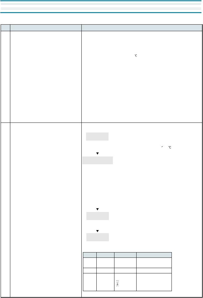
OPERATION AND FUCTIOLNS
NO |
CONTROL FUNCTION |
CONTROL OBJECTS |
|
CONTENTS |
REMARK |
|
1 |
DISPLAY |
CUSTOM LED |
1. Normal state |
|
||
|
|
|
|
|
|
|
|
|
|
|
|
|
|
1)SILENT Icon (Amber) is off.
2)Initial State : Both compartment’s icons indicate Middle-mode (“1”, and “2”are lit..)
2.FRZ.SET Button
1)Temperature Regulation of Freezer Compartment
2)Middle-left Icons are lit by pressing the button.
(1)  1
1  2
2  3
3  Q.F
Q.F
3)When Q.F Mode is set, Freezer Mode’s Icons (middle-left) are on and off 3 times, then only Q.F LED(red) is lit.
3.REF.SET Button
1)Temperature Regulation of Freshfood Compartment.
2)Middle-right Icons are lit by pressing the button.
(1)  1
1  2
2  3
3  Q.R
Q.R
3)When Q.R Mode is set, Refrigerator Mode’s Icons (middle-right) are on and off 3 times, the only Q.R LED(red) is lit.
4.SILENT Button
1)SILENT Mode starts by presssing the button.
-SILENT Icon is LIT.
-All the other LED is off.
2)The mode is finished by pressing the button once again.
-The Icon turns off and it returns to previous[normal] state.
3)The mode ends by itself in 130minutes after its start.
-The Icon turns off.
-All the other LED is off.
10

OPERATION AND FUCTIOLNS 
NO |
CONTROL FUNCTION |
CONTROL OBJECTS |
|
|
CONTENTS |
|
|
2 |
Temperature Regulation |
1. COMP |
1. Temperature regulation by FRZ.SET Button. |
|
|||
|
of Freezer Compartment |
2. F-FAN |
(1) |
1 |
2 |
3 |
Q.F |
|
|
|
|||||
2. COMP and F-Fan are controlled by On/Off point of each mode.
3. Freezer Compartment ON / OFF DIFF : 5
(Middle(2)-OFF : -22.5 )
4. “3 “/ “1” DIFF : 2
5. Control Point of each Mode Temp.
REMARK
Reference
ON/OFF Diff :
Fixed by Micom
STEP Diff :
Fixed by Micom
Comp&C- Fan
are Coworking
1 |
2 |
3 |
6.COMP and F-FAN are ON during Q.F Mode regardless of F-Sensor. (Approximately 150minutes)
3 |
Temperature Regulation of |
1. COMP |
1. Temperature regulation by REF.SET Button. |
|
|||
|
Refrigerator (Freshfood |
2. R-FAN |
(1) |
1 |
2 |
3 |
Q.F |
|
Compartment) |
|
|||||
2.R-Fan is controlled by On/Off-point of each mode.
3.ON / OFF DIFF : 0.35 (Middle(“1”) Off-point : -1.0
 )
)
4.“3” / ”1” DIFF : 2
Temp.
Weak-Refrigeration
1 |
2 |
3 |
5.Prevention of Weak-refrigeration
1)When weak-refrigeration is sensed, COMP turns on regardless of F-Sensor.
2)When R-Sensor reaches to R-Fan Off-point, COMP is controlled by F-Sensor and R-FAN turns off.
3)Sensing point of weak-refrigeration ; R-S Off-point of each mode +7
4)Finishing point of weak-refrigeration ; same as R-S Off-point
ON/OFF, Diff :
Can not be changed
STEP DIFF :
Can not be changed
6. Q.R(Quick Refrigeration) continues for 40minutes.
11

 OPERATION AND FUCTIOLNS
NO |
CONTROL FUNCTION |
CONTROL OBJECTS |
CONTENTS |
REMARK |
3 |
Temperature Regulation of |
1. COMP |
* In case Q.R starts during 1(refrigeration) mode |
|
|
Refrigerator (Freshfood |
2. R-FAN |
Temp. |
|
|
Compartment) |
|
|
|
|
|
|
|
|
|
|
|
|
1 |
|
|
|
Over |
3 |
|
|
|
refrigeration |
off point
Time
Q.R(40min.)
4 |
SILENT Control |
1. COMP |
|
|
2. R-FAN |
3. F-FAM
4. Custom LED
1)R-Fan and COMP continue to be On until the R-Sensor reaches to Off-point(-7 ) of over-refrigeration.
2)It continues to be 3 until Q.R ends after reaching to Off-point of overrefrigeration.
3)It returns to normal[previous] state when Q.R (40 minutes) ends.
1.SILENT Mode starts by pressing the button.
2.Terms to start SILENT Mode
 F-Sensor
  15
15 
 Restart of SILENT within 40 minutes after the mode
 F-Sensor error
 Door Switch error
 In Defrosting Mode (HTR Defrosting, Pause, Fan-delay)
 SILENT starts if conditions
  to
to  happen.
3.Once SILENT starts, all the electric devices (COMP, F-Fan, R-Fan) turn Off and only SILENT Icon is lit.
4.Terms to finish SILENT Mode  F-Sensor
  -9
-9 
 More than 130 minutes of Limit-time
 F-Sensor error
 In case any other button is pressed during SILENT Mode
 Door opened time is more than 30 seconds during the mode.
 If the mode is finished by
  ,
,  and
and  , F/R-Fan Delay time is set to 5 minutes, and prevention of SILENT Restart time is set to 40 minutes.
5.When the mode is finished all the electric devices and C-LEDs return to normal [previous] state.
6.Pre-cool continues after SILENT Mode.
7.Q.F and Q.R continue after SILENT Mode for the rest time.
12
OPERATION AND FUCTIOLNS 
NO |
CONTROL FUNCTION |
CONTROL OBJECTS |
|
CONTENTS |
5 |
Defrosting Period |
1. Defrosting Mode |
1. What to be considered in determining Defrosting Period |
|
|
|
|
1) |
Total Run-time of COMP : 6, 8, 10, 12, 14 hours |
|
|
|
2) Running-rate of COMP (each 2hours running-rate) : more than 80% |
|
|
|
|
3) |
Total time of Door openings : 10minutes |
|
|
|
4) |
Total Time (COMP-On + COMP-Off) : 60hours |
|
|
|
5) |
Ambient Temperature : more than 35 |
|
|
|
6) |
In each Error : R1, F1, D1, F3, RT-S, Door-SW Error |
|
|
|
2. Terms to start Defrosting Period |
|
|
|
|
1) |
The Defrosting starts with the following conditions, in case total |
|
|
|
|
COMP-run time passes 6, 8, 10 or 12hours |
|
|
|
|
¨ç when an Error occurs |
|
|
|
|
¨è when running-rate of COMP is more than 80% |
é¨ when total Door-opening time is more than 10minutes ê¨ when the ambient temperature is more than 35
2) Defrosting starts unconditionally when total COMP-run time passes 14 hours, under the condition that terms of 1) are not satisfied.
3) Defrosting starts immediately when Total-time (COMP-On + Off time) is more than 60 hours, under the condition that terms of 1) and/or 2) are not satisfied.
6 |
Defrostiong Mode |
1.COMP |
|
|
2. F-FAN |
3. R-FAN
4. HEATER
1. Defrosting Period
Pre-cool |
1) Time : 50minutes |
|
2) COMP and F-Fan are On, R-fan is in |
||
|
||
|
Control, and HTR is off |
|
|
3) Pre-cool turns off when F-Sensor -27 . |
 Heater Defrostiong
Pause
Fan-delay
1)Heater turns off when D-Sensor  10
10 .
.
2)Limit time : 80minutes
3)Heater continues to be On for 40 minutes of limit time when D-Sesor is in error.
4)Limit time
 30seconds: Heater continues to be On after Defrosting regardless of D-Sensor temperature.
 40minutes: in case of D1-Error
 80minutes: in normal control state
1)Time : 4minutes
2)COMP, F-Fan and R-Fan are Off.
1)Time : 5minutes
2)Only COMP is On, while F or R-Fan is Off.
2. Output Control and Limit Time of each Defrosting Mode
|
Pre-cool |
HTR Defrosting |
Pause |
Fan-delay |
COMP |
ON |
OFF |
OFF |
ON |
F-Fan |
ON |
OFF |
OFF |
OFF |
R-Fan |
Control |
OFF |
OFF |
OFF |
Heater |
OFF |
ON |
OFF |
OFF |
Limit |
|
80 min. |
|
|
Time |
50 min. |
40 min. |
4 min. |
5 min. |
|
|
(In D-Sensor error) |
|
|
REMARK
C-Fan and COMP are co-working.
13
 Loading...