


 Loading...
User’s Manual
LINE THERMAL PRINTER
MODEL CBM-230/231
Japan CBM Corporation
Information Systems Div.

CBM-230/231 User’s Manual
1996.08.02(10-DCL)15
|
Declaration of Conformity |
|
Manufacturer's Name : |
: Japan CBM Corporation |
|
Manufacturer's Address |
: 1-1-7, Okubo, Shinjuku-ku, Tokyo |
|
|
169, Japan |
|
Declare the Product |
|
|
Product Name |
Thermal Printer |
|
Model Number (s) |
CBM230 Series |
|
|
(CBM230R,CBM230P,CBM231R, BM231P |
|
|
(S.NO.95Y0001 - |
) |
Conform to the following Standards |
|
|
LVD |
: EN60950 |
:1992+A1+A2:1993 |
EMC |
: EN55022 |
:1994 Class A |
|
: EN61000-3-2 |
:1995 |
|
: EN50082-1 |
:1992 |
|
: IEC801-2 |
:1991 4KV CD, 8KV AD |
|
: IEC801-3 |
:1984 3V/m, 27MHz-500MHz |
|
: IEC801-4 |
:1988 0.5KV Signal Line 1KV AC mains |
Supplementary Information
"The product complies with the requirements of the Low Voltage Directive 73/23/EEC, 93/68/EEC and the EMC Directive 89/336EEC, 92/31/EEC, 93/68EEC"
Signature
Place |
Tokyo, Japan |
|
|
Date |
November, 1995 |
Full Name : Koji Tanabe
Position : General Manager
R & D Department
Europe Contact :
Europe Liaison Office
Kuruisweg 805, Holland Office Center Building
3-2132 NG Hoofddorp, the Netherlands
Warning
This is a Class A products. In a domestic environment this product may cause radio interference in which case the user may be required to take adequate measures.
This declaration is applied only for 230V model.
CITIZEN |
2 |

CBM-230/231 User’s Manual
IMPORTANT SAFETY INSTERUCTIONS
•Read all of these instructions and save them for later reference.
•Follow all warnings and instructions marked on the product.
•Unplug this product from the wall outlet before cleaning. Do not use liquid or aerosol cleaners. Use a damp cloth for cleaning.
•Do not use this product near water.
•Do not place this product on an unstable cart, stand of table. The product may fall, causing serious damage to the product.
•Slots and openings on the cabinet and the back or bottom are provided for ventilation.
To ensure reliable operation of the product and to protect it form overheating, do not block or cover these openings. The openings should never be blocked by placing the product on a bed, sofa, rug of other similar surface.
This product should never be placed near or over a radiator or heat register.
This product should not be placed in a built-in installation unless proper ventilation is provided.
•This product should be operated from the type of power source indicated on the marking label. If you’re not sure of the type of power available, consult your dealer or local power company.
•Do not allow anything to rest on the power cord. Do not locate this product where the cord will be walked on.
•In an extension cord is used with this product, make sure that the total of the ampere ratings on the products plugged into the extension cord do not exceed the extension cord ampere rating.
Also, make sure that the total of all products plugged into the wall outlet dose not exceed 15 amperes.
•Never push objects of any kind into this product through cabinet slots as they may touch dangerous voltage points or short out parts that could result in a risk of fire or electric shock. Never spill liquid of any kind on the product.
•Except as explained elsewhere in this manual, don’t attempt to service this product yourself. Opening and removing those covers that are marked “Do Not Remove” may expose you to dangerous voltage points or other risks. Refer all servicing on those compartments to service personnel.
•Unplug this product from the wall outlet and refer servicing to qualified service personnel under the following conditions:
A.When the power cord or plug is damaged or frayed
B.If liquid has been spilled into the product.
C.If the product has been exposed to rain or water.
D.If the product dose not operate normally when the operating instructions are followed. Adjust only those controls that are covered by the operating instructions since improper adjustment of other controls may result in damage and will often require extensive work by a qualified technician to restore the product to normal operation.
E.If the product has been dropped the cabinet has been damaged.
F.If the product exhibits a distinct change in performance, indicating a need for service.
CITIZEN |
3 |

CBM-230/231 User’s Manual
IMPORTANT: This equipment generates, uses, and can radiate radio frequency energy and if not installed and used in accordance with the instruction manual, may cause interference to radio communications. It has been tested and found to comply with the limits for a Class A computing device pursuant to Subpart J of Part 15 of FCC Rules, which are designed to provide reasonable protection against such interference when operated in a commercial environment. Operation of this equipment in a residential area is likely to cause interference, in which case the user at his own expense will be required to take whatever measures may be necessary to correct the interference.
CAUTION: Use shielded cable for this equipment.
For Uses in Canada
This digital apparatus does not exceed the class A limits for radio noise emissions from digital, apparatus, as set out in the radio interface regulations of the Canadian department of communications.
CITIZEN |
4 |

CBM-230/231 User’s Manual
|
|
CONTENTS |
1 GENERAL DESCRIPTION .............................................................................................................................................. |
6 |
|
1.1 |
Features ....................................................................................................................................................... |
6 |
1.2 |
Precautions for Installation ........................................................................................................................... |
6 |
2 BASIC SPECIFICATIONS ............................................................................................................................................... |
7 |
|
2.1 |
Model Classification ..................................................................................................................................... |
7 |
2.2 |
Specifications List ........................................................................................................................................ |
8 |
2.3 |
Specifications for Printing Paper ................................................................................................................... |
9 |
2.3.1 Specified Paper ...................................................................................................................................... |
9 |
|
|
2.3.2 Printing Position .................................................................................................................................. |
9 |
|
2.3.3 Head and Cutter Positional Relations.................................................................................................... |
9 |
3 APPEARANCE AND COMPONENT PARTS............................................................................................................... |
10 |
|
4 OPERATION................................................................................................................................................................... |
11 |
|
4.1 |
Connecting the Interface Cable.................................................................................................................... |
11 |
4.2 Connecting the Drawer Kick Connector....................................................................................................... |
12 |
|
4.3 |
Inserting the Paper Roll .............................................................................................................................. |
13 |
4.4 |
Operation Panel .......................................................................................................................................... |
17 |
4.5 |
Opening the Auto Cutter(CBM-231) ........................................................................................................... |
18 |
5 SETTING OF DIP SWITCHES....................................................................................................................................... |
19 |
|
6 PARALLEL INTERFACE............................................................................................................................................... |
22 |
|
6.1Specifications .............................................................................................................................................. |
22 |
|
6.2 |
Connector's Pin Configuration..................................................................................................................... |
22 |
6.3 |
Input / Output Signals................................................................................................................................. |
23 |
6.3.1 Input / Output Signals.......................................................................................................................... |
23 |
|
6.3.2 Electrical Characteristics...................................................................................................................... |
24 |
|
6.3.3 Timing Chart ....................................................................................................................................... |
25 |
|
6.3.4 Data Receiving Control........................................................................................................................ |
25 |
|
6.3.5 Buffering ............................................................................................................................................. |
25 |
|
7 SERIAL INTERFACE..................................................................................................................................................... |
26 |
|
7.1 |
Specifications ............................................................................................................................................. |
26 |
7.2 |
Connector's Pin Configuration..................................................................................................................... |
27 |
7.3 |
Input / Output Signals................................................................................................................................. |
28 |
7.3.1 Input / Output Signals.......................................................................................................................... |
28 |
|
7.3.2 Data Configuration .............................................................................................................................. |
29 |
|
7.3.3 Error Detection .................................................................................................................................... |
29 |
|
7.3.4 Data Receiving Control........................................................................................................................ |
30 |
|
7.3.5 Buffering ............................................................................................................................................. |
30 |
|
7.3.6 Electrical Characteristics...................................................................................................................... |
31 |
|
8 DRAWER KICK CONNECTOR.................................................................................................................................... |
32 |
|
8.1 |
Specifications ............................................................................................................................................. |
32 |
8.2 |
Connector's Pin Configuration..................................................................................................................... |
32 |
8.3 Drive Circuit ............................................................................................................................................ |
32 |
|
9 PRINT CONTROL FUNCTION ..................................................................................................................................... |
33 |
|
9.1Control Codes List....................................................................................................................................... |
33 |
|
9.2Input Data Format ....................................................................................................................................... |
34 |
|
10 CHARACTER CODE TABLE...................................................................................................................................... |
54 |
|
10.1International .............................................................................................................................................. |
54 |
|
10.2 International Character Code Table........................................................................................................... |
55 |
|
Appendix 1. Precaution and Maintenance ........................................................................................................................... |
56 |
|
Appendix 2. External Dimensions ....................................................................................................................................... |
57 |
|
Appendix 3. Block Diagram................................................................................................................................................ |
59 |
|
CITIZEN |
5 |

CBM-230/231 User’s Manual
1 GENERAL DESCRIPTION
This is a small line thermal printer developed to be used for various data communication terminals such as POS terminals, kitchen printers.
With its abundant features, it can be widely used for various types of applications. Read this manual thoroughly prior to using the printer to understand its contents.
1.1Features
1.Compact, light-weight, and small installation area required
2.High speed and low noise due to line thermal printing
3.High reliability due to long-life printing head and simple mechanism
4.Input buffer incorporated
5.Capable of printing a bar codes (exclusive command)
6.Drawer kickout interface incorporated
7.Equipped with an auto cutter (CBM-231)
8.User-Defined character registration function(95 characters)
9.Easy handling due to incorporated power supply
1.2Precautions for Installation
1.Upon unpacking the printer, make sure that the following parts are contained in the package.
Printer main body |
1 unit |
Sample paper roll |
1 roll |
Instruction manual |
1 copy |
2.Install the printer on a flat and stable desk or table.
3.Do not install the printer near a heater or in the direct sunshine.
4.Do not use the printer in a high-temperature, high-humidity, or contaminated environment.
5.Prepare a separate AC power supply from other equipment which causes noises.
6.Connect only a specified solenoid to the drawer kick connector.
7.When transporting or not using the printer for a long period of time, leave the printing head kept up.
CITIZEN |
6 |

CBM-230/231 User’s Manual
2 BASIC SPECIFICATIONS
2.1 Model Classification
The model is classified by the following designation method.
CBM-230 -- |
R |
F |
120 |
|
|
|
|
|
|
|
|
AC power source |
|
Model |
|
120 : AC120V(60Hz) |
||
CBM-230 |
: Standard model |
|
230 : AC230V(50/60Hz) |
|
CBM-231 |
: Auto cutter incorporated |
|
|
|
|
|
|
Character set |
|
|
|
|
||
|
|
|
F : International use |
|
Interface
R : Serial (RS-232C)
P : Parallel (Conforms to CENTRONICS)
CITIZEN |
7 |

CBM-230/231 User’s Manual
2.2 Specifications List
Item |
|
Description |
|
Printing system |
Line thermal dot printing system |
|
|
Print width |
72 mm/576 dots |
|
|
Dot density |
8 dots / mm (Horizontal, Vertical) |
|
|
Printing speed |
62.5 mm/sec. (at Max. speed) |
(500-dot Line / sec.) |
|
No. of columns |
48 columns (12 x 24, Font A) |
*(42 columns) |
|
|
64 columns ( 9 x 17, Font B) |
*(56 columns) |
|
Character size |
1.25 mm x 3.00 mm (12 x 24, Font A) |
|
|
|
0.88 mm x 2.13 mm ( 9 x 17, Font B) |
|
|
Character type |
Alphanumeric, International characters |
|
|
Bar code type |
UPC-A/E, JAN(EAN) 13 columns/18 columns, ITF |
||
|
CODE 39, CODE 128, CODABAR |
|
|
Line pitch |
1/6 inch (approx. 4.23mm) (can be selected by Command) |
||
|
Min. 1/203 inch |
|
|
Paper |
Thermal roll paper 80 mm x Ø83 mm |
|
|
|
(Refer to Specifications for Print Paper) |
|
|
Interface |
Serial (RS-232C), Parallel (Conforms to Centronics.) |
||
Input buffer |
72 byte / 4 K byte (Can be selected with the Dip switch) |
||
Power supply voltage |
120 V AC ± 10 %, 60 Hz |
|
|
|
230 V AC ± 10 %, 50 / 60 Hz |
|
|
Power consumption |
100W |
|
|
Weight |
1.70 kg (CBM-230), 1.85 kg (CBM-231) |
|
|
External dimensions (main body) |
145 (W) x 216 (D) x 150 (H) |
|
|
Operating temperature/humidity |
5 - 40 °C |
|
|
Storage temperature/humidity |
-20 - 60 °C |
|
|
Reliability |
Print head’s life : |
|
|
|
Pulse resistance |
50 million pulses |
|
|
Wear resistance |
30 Km |
|
|
(Printing ratio 12.5%, normal temperature, |
||
|
normal humidity, recommended paper) |
||
|
Auto cutter’s life : |
|
|
|
300,000 cut (Normal temperature, |
||
|
normal humidity, recommended paper) |
||
|
|
|
|
* Special ROM only |
|
|
|
CITIZEN |
8 |
CBM-230/231 User’s Manual
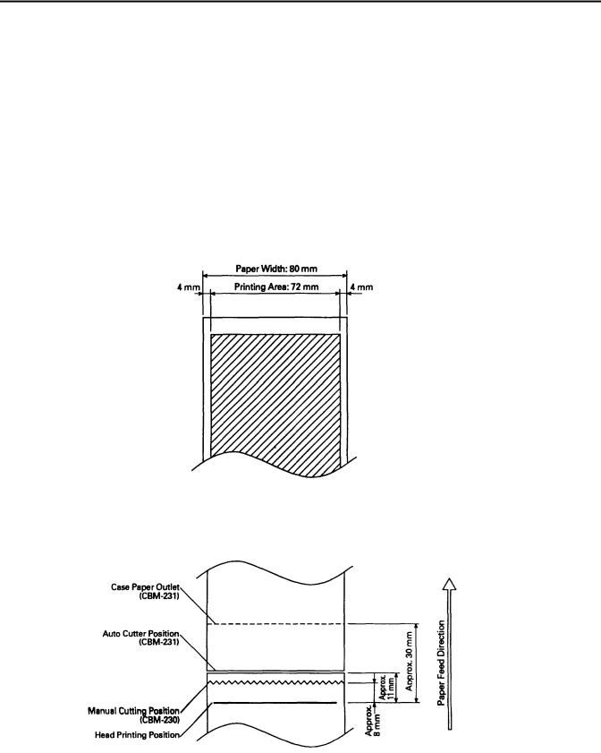
2.3 Specifications for Printing Paper
2.3.1 Specified Paper
Type |
: Thermal paper |
Paper width |
: 80+0 or -1 mm |
Paper thickness |
: 65 ± 5 Micro m |
Roll diameter |
: Ø83mm or less |
Print surface |
: Outside of the roll(surface) |
Recommended paper : TF50KS-E2C made by Nihon Paper Mill. or other equivalent
Core : Ø12 mm (inner diameter), Ø18 mm (outer diameter)
[Caution] Do not paste the paper to the core.
2.3.2 Printing Position
2.3.3 Head and Cutter Positional Relations
CITIZEN |
9 |
CBM-230/231 User’s Manual
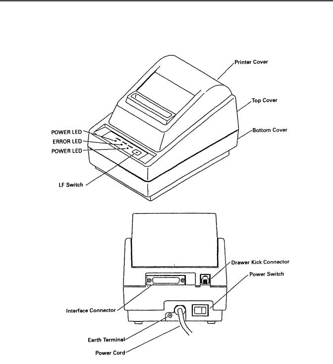
3 APPEARANCE AND COMPONENT PARTS
CITIZEN |
10 |
CBM-230/231 User’s Manual
4OPERATION
4.1Connecting the Interface Cable
1.Turn off the power.
2.Confirm the vertical direction of a cable terminal and connect it to the interface connector.
3.Fix the cable terminal.
Serial interface |
: Tighten screws to fix. |
Parallel interface |
: Turn a fixture in an arrow direction to fix. |
4. Connect the cable to the computer.
CITIZEN |
11 |
CBM-230/231 User’s Manual
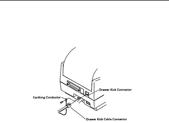
4.2Connecting the Drawer Kick Connector
1.Turn off the power.
2.Confirm the vertical direction of a drawer kick cable connector and insert it into the drawer kick connector on the back of the printer.
3.Using a screw, fix a drawer's earthing conductor to the earth terminal of the printer.
[Caution] Connect only a specified drawer(solenoid) to the drawer kick connector.
CITIZEN |
12 |
CBM-230/231 User’s Manual
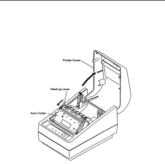
4.3 Inserting the Paper Roll
[Caution] Be sure to use a specified paper roll.
1.Open the printer cover.
2.Shift the head-up lever in an arrow direction to move up the printing head.
[Caution] When setting the paper roll, you do not have to open the auto cutter. (CBM-231)
CBM-231
CITIZEN |
13 |

CBM-230/231 User’s Manual
3.Using the scissors, cut the end of the paper at a right angle. [Caution] Do not insert the paper with its end fluffed or bent.
4.Confirm the winding direction of the paper roll. Opening the paper holder in the direction of the arrow, set the paper and hold the core center properly.
[Caution] Make sure that the paper roll rotates smoothly without tilting the paper.
CITIZEN |
14 |
CBM-230/231 User’s Manual
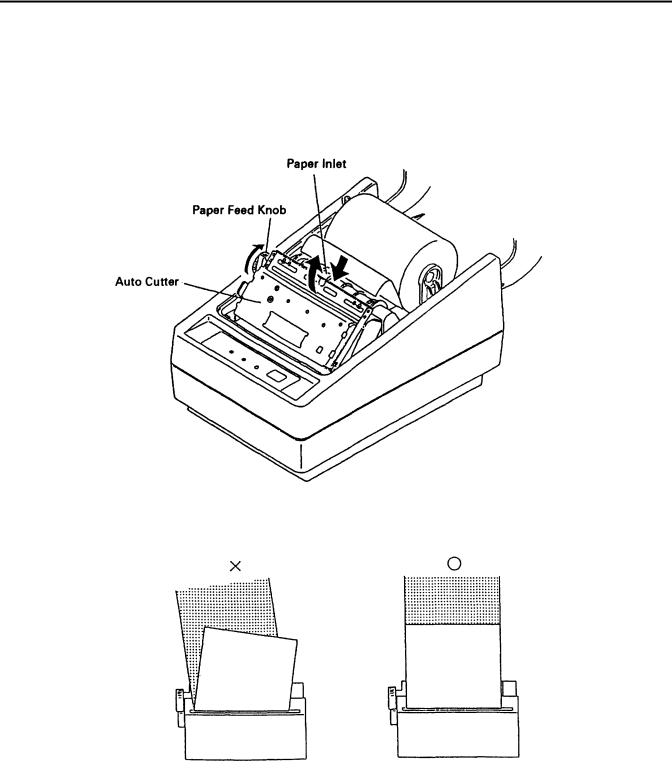
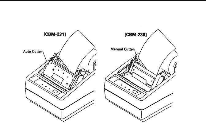
5.Insert the end of the paper into the paper inlet, turn the paper feed knob in the direction of the arrow to feed out the paper about 5 cm from the paper outlet of the auto cutter or nose of the manual cutter. (The figure below shows the CBM-231).
[Caution] Do not turn the paper feed knob when the printing head is in its down position.
6. When the paper is tilting, correct it and move the printing head down.
CITIZEN |
15 |
CBM-230/231 User’s Manual
7. Cut off the surplus paper at the edge of the paper outlet of the auto cutter or blade of the manual cutter.
8.Close the printer cover. You are finished with setting of the paper roll. [Caution] Do not open the printer cover during printing.
9.When removing the remaining paper upon its replacement with new one, pull it out straight with the printing head kept up.
10.When using the auto loading function, follow the procedure below.
(1)Change the setting of the DIP switch to the auto loading mode. (Turn on DS1-3)
(2)Move the printing head up.
(3)Insert the end of the paper straight into the paper inlet of the printer and move down the printing head. The paper is automatically pulled in by a constant amount.
(4)Close the printer cover to finish setting of the paper roll.
[Caution] When the paper is tilting, move up the printing head and correct it manually.
CITIZEN |
16 |

CBM-230/231 User’s Manual
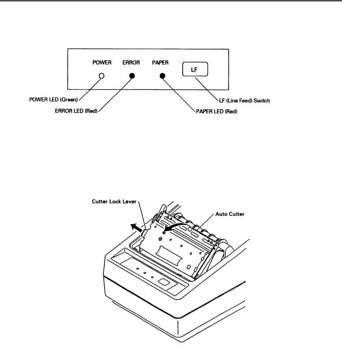
4.4Operation Panel
1.POWER LED(green)
Illuminated when the power is supplied.
2.ERROR LED(red)
Indicates different errors, depending on the illuminated or blinking condition.
ERROR DETAIL DISPLAY PATTERN |
|
|
|
|
|
|
|
|
RESETTING METHOD |
|||||
|
|
|
|
|
|
|
|
|
|
|
|
|
|
|
Printer cover open |
|
Illuminated |
|
|
|
|
Close the cover |
|||||||
Head Up |
|
Illuminated |
|
|
|
|
Move down the head |
|||||||
Memory check |
|
|
|
|
|
|
|
|
|
|
|
|
Disabled |
|
|
|
|
|
|
|
|
|
|
|
|||||
|
|
|
|
|
|
|
|
|
|
|
|
|
|
|
Head overheat |
|
|
|
|
|
|
Automatically reset by |
|
|
|
|
|
|
|
temperature drop |
|
|
|
|
|
|
|
|
|
|
|
|
|
|
|
|
Macro execution wait |
|
|
|
|
|
|
Press the LF switch |
|
|
|
|
|
|
|
|
Cutter motor lock |
|
|
|
|
|
|
|
|
Eliminate paper jam |
|
|
|
|
|
|||||
|
|
|
|
|
|
|
|
|
and press LF switch |
|
|
|
|
|
|
|
|
|
|
3 PAPER LED(red) |
|
Near end enabled |
: Illuminated when the paper is near its end (Stops after printing the set length) |
Near end disabled |
: Illuminated when the paper is at its end (Stops printing) |
[Caution] Use the DIP switch to enable or disable the near end detecting function.
4 LF switch
Pressing this switch for a short time feeds the paper by one line. Holding it down feeds the paper continuously. In case of macro execution wait, pressing the LF switch executes it.
[Caution] Depending on a selection of the DIP switch, the paper can be fed when the cover is opened.
CITIZEN |
17 |
CBM-230/231 User’s Manual
5 LF switch and power switch
Self-printing is performed by turning on the power switch with the LF switch held down.
4.5 Opening the Auto Cutter(CBM-231)
When the paper is jamming or when you open the auto cutter in order to clean the head, raise the auto cutter, pulling the cutter lock lever in the direction of the arrow.
[Caution] Immediately after printing, the printing head and motor have a high temperature. Never touch the printing head and motor when you open the auto cutter.
CITIZEN |
18 |
Loading...