

CBM-272
— 1 —

Declaration of Conformity
Manufacturer’s Name : Japan CBM Corporation
Manufacturer’s Address : CBM Bldg., 5-68-10, Nakano, Nakano-ku
Tokyo, 164-0001, Japan
Declare the Product
Product Name Line Thermal Printer
Model Number(s) CBM-272 Series
(CBM-272R, CBM-272P)
(S.No.0190001 ~ )
Conform to the following Standards
LVD : EN60950 :
EMC : EN55022 :
: EN61000-3-2 :
: EN61000-3-3 :
: EN55024 :
: EN61000-4-2 :
: EN61000-4-3 :
: EN61000-4-4 :
: EN61000-4-5 :
: EN61000-4-6 :
: EN61000-4-8 :
:
EN61000-4-11: 1994 0%, 5000ms/70%, 500ms/0%, 10ms
Supplementary Information
“The product complies with the requirements of the Low Voltage Directive 73/
23/EEC, 93/68/EEC and the EMC Directive 89/336/EEC, 92/31/EEC, 93/68/EEC”
A4: 1997, A11: 1997
1998 Class A
1995 +A1:1998+A2:1998
1995
1998
1995 ±4KV CD, ±8 KV AD
1996
4.5 V/m, 80 MHz-1000 MHz AM 1 KHz 80 %
1995
±1.0 KV (AC Mains), ±0.5 KV (Signal Lines)
1995
±1 KV (Normal mode), ±2 KV (Common mode)
1996 3 V, 0.15 MHz-80 MHz AM 1 KHz 80 %
1993 50 Hz, 3 A/m
Place Tokyo, Japan Signature
Date August 2001
Full Name : Mikio Moriya
Position : General Manager
R & D Department
European Contact :
Norco Declaration AB
Box 7146 S-250 07 Helsingborg Sweden
Warning : This is a Class A product. In a domestic environment this product may cause radio
interference in which case the user may be required to take adequate measures.
This declaration is applied only for 230 V model.
— i —

IMPORTANT SAFETY INSTRUCTIONS
• Read all of these instructions and save them for future reference.
• Follow all warnings and instructions marked on the product.
• Unplug the product from the wall outlet before cleaning. Do not use liquid or aerosol
cleaners. Use a damp cloth for cleaning.
• Do not use the product near water.
• Do not place the product on an unstable cart, stand or table. The product may fall,
causing serious damage to the product.
• Slots and openings on the back or bottom of the case are provided for ventilation. To
ensure reliable operation of the product and to protect it from overheating, do not
block or cover these openings. The openings should never be blocked by placing the
product on a bed, sofa, rug of other similar surface. The product should never be
placed near or over a radiator or heater. The product should not be placed in a built-in
installation unless proper ventilation is provided.
• The product should be operated from the type of power source indicated on the
marking label. If you are not sure of the type of power available, consult your dealer
or local power company.
• Do not allow anything to rest on the power cord. Do not place the product where the
cord will be walked on.
• If an extension cord is used with the product, make sure that the total of the ampere
ratings of the products plugged into the extension cord does not exceed the extension
cord ampere rating. Also, make sure that the total of all products plugged into the wall
outlet does not exceed 15 amperes.
• Never push objects of any kind into the product through cabinet slots as they may
touch dangerous voltage points or short out parts that could result in a risk of fire or
electric shock. Never spill liquid of any kind on the product.
• Except as explained elsewhere in this manual, do not attempt to service the product by
yourself. Opening and removing the covers that are marked "Do Not Remove" may
expose you to dangerous voltage points or other risks. Refer all servicing on those
compartments to service personnel.
• Unplug the product from the wall outlet and refer servicing to qualified service
personnel under the following conditions:
A. When the power cord or plug is damaged or frayed.
B. If liquid has been spilled into the product.
C. If the product has been exposed to rain or water.
D. If the product does not operate normally when the operating instructions are
followed. Adjust only those controls that are covered be the operating instructions
since improper adjustment of other controls may result in damage and will often
require extensive work by a qualified technician to restore the product to normal
operation.
E. If the product has been dropped or the cabinet has been damaged.
F. If the product exhibits a distinct change in performance, indicating a need for
service.
• Please keep the poly bag which the printer is packed in away from children or throw it
away to prevent children from putting it on. Putting it on may cause suffocation.
— ii —

WICHTIGE SICHERHEITSANWEISUNGEN
• Lesen Sie die nachfolgenden Anweisungen sorgfältig durch und bewahren Sie sie auf.
• Befolgen Sie alle auf dem Drucker vermerkten Hinweise und Anweisungen. Vor dem
Reinigen grundsätzlich Stecker aus der Steckdose ziehen. Keine Flüssigkeiten oder
Aerosolreiniger benutzen. Nut mit einem feuchten Tuch abwischen.
• Der Drucker darf nicht in der Nähe von Wasser aufgestellt werden.
• Drucker nicht auf einem unstabilen Wagen, Stand oder Tisch aufstellen. Der Drucker
könnte herunterfallen und dabel beschädigt werden.
• Schlitze und Öffnungen im Gehäuse, in der Rückwand und im Boden dienen der
Belüftung. Sie dürfen keinesfalls zugedeckt oder blockiert werden, da sich der Drucker
sonst überhitzt. Drucker nicht auf ein Bett, Sofa, Teppich oder dergleichen stellen.
Drucker nicht in der Nähe eines Heizkörpers aufstellen. Drucker darf nicht eingebaut
werden, falls nicht für ausreichende Beluftüng gesorgt ist.
• Drucker nur mit der auf dem Typschild angegebenen Spannung betreiben. Wenn Sie
sich nicht sicher sind, fragen Sie ihren Händler oder ihr zuständiges Elektrizitätswerk.
• Nichts auf das Stromanschlußkabel stellen. Kabel muß so verlegt werden, daß man
nicht darauftreten kann.
• Ein etwaiges Verlängerungskabel muß der Stromstärke aller daran angeschlossenen
Geräte entsprechen.
• Keine Gegenstände in die Gehäuseschlitze schieben.
• Drucker darf nur da gewartet werden, wo im Handbuch angegeben, Öffnen und.
Abnehmen von Abdeckungen, die mit "Do not remove" gekennzeichenet sind, könnte
gefährliche spannungführende Stellen oder sonstige Gefahrenpunkte freilegen. Die
Wartung solcher Stellen darf grundsätzlich nur von besonders ausgebildetem
Fachpersonal vorgenommen werden.
A. Wenn das Stromanschlußkabel oder der Stecker beschädigt oder durch-gescheuert
ist.
B. Wenn Flüssigkeit auf dem Drucker verschüttet wurde.
C. Wenn der Drucker im Regen gestanden hat oder Wasser darauf verschüttet wurde.
D. Wenn der Drucker trotz genauer Befolgung der Betriebsvorschriften nicht richtig
arbeitet. Nur die in der Bedienungsanleitung angegebenen Einstellungen
vornehmen. Ein Verstellen anderer Bedienungselemente könnte den Drucker
beschädigen und macht umständliche Arbeiten eines qualifizierten Technikers
erforderlich, um den Drucker Wieder auf den normalen Betrieb einzustellen.
E. Wenn der Drucker heruntergefallen ist oder das Gehäuse beschädigt wurde.
F. Wenn der Drucker in seiner Leistung nachläßt.
• Bitte halten Sie den Kunststoffbeutel, in den der Drucker verpackt ist, von Kindern
entfernt oder entsorgen Sie ihn, damit er nicht in die Hände von Kindern gerät. Das
Überstulpen des Beutels kann zum Ersticken führen.
Lärmemission kleiner 70dBA
— iii —

IMPORTANT: This equipment generates, uses, and can radiate radio frequency
energy and if not installed and used in accordance with the instruction manual,
may cause interference to radio communications. It has been tested and found to
comply with the limits for a Class A computing device pursuant to Subpart J of
Part 15 off FCC Rules, which are designed to provide reasonable protection against
such interference when operated in a commercial environment. Operation of this
equipment in a residential area is likely to cause interference, in which case the
user at his own expense will be required to take whatever measures may be
necessary to correct the interference.
CAUTION: Use shielded cable for this equipment.
Sicherheitshinweis
Die Steckdose zum Anschluß dieses Druckers muß nahe dem Grät angebracht und
leicht zugänglich sein.
For Uses in Canada
This digital apparatus does not exceed the class A limits for radio noise emissions
from digital, apparatus, as set out in the radio interference regulations of the
Canadian department of communications.
Pour L’utilisateurs Canadiens
Cet appareil numérique ne dépasse pas les limites de carégorie a pour les
émissions de bruit radio émanant d’appareils numériques, tel que prévu dans les
réglements sur l’interférence radio du départment Canadien des communications.
— iv —

<CAUTIONS>
• Prior to using the printer, be sure to read this User's Manual thoroughly. Please
keep it handy for reference whenever it may be needed.
• The information contained herein may be changed without prior notice.
• Reproduction of part or all of this User's Manual without permission is strictly
prohibited.
• Never service, disassemble, or repair parts that are not mentioned in this User's
Manual.
• Note that we will not be responsible for damages attributable to a user's incorrect
operation/ handling or an improper operating environment.
• Operate the printer only as described in this User's Manual; otherwise accidents
or problems may result.
• Data are basically temporary; they cannot be stored or saved permanently or for
a long time. Please note that we will not be responsible for damages or losses of
profit resulting from losses of the data attributable to accidents, repairs, tests,
and so on.
• If you have any questions or notice any clerical errors or omissions regarding the
information in this manual, please contact our office.
• Please note that, notwithstanding Item 8 above, we will not be responsible for
any effects resulting from operation of the printer.
— v —
SAFETY PRECAUTIONS — BE SURE TO OBSERVE
In order to prevent hazards to an operator or other persons and damage to
property, be sure to observe the following precautions.
• The following describes the degrees of hazard and damages that can occur if the
given instructions are neglected or the printer is incorrectly operated.
WARNING
Negligence of this precaution may result in death or serious injury.
CAUTION
Negligence of this precaution may result in injury or damage to property.
This is an illustration mark used to alert your attention.
This is an illustration mark used to indicate such information as an
i
instruction or the like.
— vi —

WARNING
● Never handle the printer in the following manners, as it may break, become out
of order, or overheat causing smoke and resulting in fire or electric shock. If
the printer is used in an abnormal condition, such as when broken, then
problems, smoke emission, abnormal odor/noise, and fire can result. If an
abnormal condition exists, be sure to disconnect the power plug from a plug
socket, and contact our dealer. Never repair the printer on your own - it is very
dangerous.
• Do not allow the printer to receive a strong impact or shock, such as kicking,
stomping, hitting, dropping, and the like.
• Install the printer in a well-ventilated place. Do not use it in such a manner
that its ventilation port will be blocked.
• Do not install the printer in a place like a laboratory where chemical reactions
are expected, or in a place where salt or gases are contained in the air.
• Do not connect/disconnect a power cord or a data cable, while holding the
cable. Do not pull, install, use, or carry the printer in such a manner that force
will be applied to the cables.
• Do not drop or insert any foreign substances, such as clips or pins, into the
printer.
• Do not spill any liquid or spray any chemical-containing liquid over the printer.
If any liquid is spilled on it, turn off the power, disconnect the power cable and
power cord from the plug socket, and so on, and contact our dealer.
• Never disassemble or remodel the printer. Negligence of this may cause fire
or electric shock.
• Use the printer only with the specified commercial power supply and AC
adapter. Negligence of this may result in fire, electric shock, or problems.
• If you drop or break the AC adapter, or if water or the like gets inside it, unplug
it immediately from the socket and contact your dealer.
• Do not damage, break, process, bend/pull by force, twist, or printing head an
AC adapter cord. Also, do not put a heavy substance on it or heat it. The AC
adapter cord could be broken, resulting in fire, electric shock, or trouble. If the
AC adapter cord is damaged, contact our dealer.
• Do not connect/disconnect the AC adapter with wet hands.
• Do not overload a single electrical outlet, using a table tap or a current tap
socket.
The printer packing bag must be discarded or kept away from children. A child
●
can suffocate if the bag is placed over the printing head.
— vii —

PRECAUTIONS FOR INSTALLATION
• Do not use or store the printer in a place exposed to fire, moisture, or direct
sunshine, or in a place near a heater or thermal device where the prescribed
operating temperature and humidity are not met, or in a place exposed to much oil,
iron powder, or dust. The printer may become out of order, emit smoke, or catch
fire.
• Do not install or use the printer in a place like a laboratory where chemical
reactions are expected, or in a place where salt or gases are contained in the air.
There is a danger of fire or electric shock.
• Install the printer on a flat, stable desk or table that is free from vibration, in a wellventilated place.
• Do not install the printer at a location where its operation could be hindered.
• Do not place anything on the printer or leave small objects, like a clip or pin, around
it. A foreign object could cause trouble if it gets inside.
• Do not use any sharp-pointed object, such as a pen, for example, to touch the
operation panel of the printer. It could cause trouble.
• Do not use the printer near a radio or TV receiver. Do not share the power from a
plug socket a radio or TV receiver is connected to. It may cause a reception
problem.
• Use the printer only at the specified power supply, voltage and frequency.
Otherwise, it may emit smoke and catch fire or cause other problems.
• Connect only the specified power source. Use of an unspecified power source
could cause trouble or smoke/fire.
• Confirm that a plug socket used for connection has sufficient capacity.
• Avoid connecting a power cable to a plug socket shared by other devices or
extending the wiring too far. It may result in the cable catching fire or a power
outage. Also, do not step on or apply an excessive force (Pull, load) to the cable,
and do not use the printer with such a force applied to it.
• Never connect a grounding cable (Frame ground) to a gas pipe. There is a danger
of explosion. When connecting or disconnecting the grounding cable, be sure to
disconnect the power cable and the power plug from the plug socket.
• When connecting/disconnecting the cables, be sure to turn off the power first,
including the connected side, and then connect/disconnect them, holding a plug
and a connector. Pulling the cable itself could cause it to snap or become
damaged.
• Connect a power cable or a connector cable securely. Avoid reversing the polarity
when connecting as internal elements may be broken or a mating device may be
adversely affected.
• Use a shielding wire or twisted pair wire for a signal line, in order to minimize noise
effect. Do not route the cable too long or connect it to a noisy device. Connection
to a noisy device could cause erroneous printing due to corrupt data, and so on.
• Use the printer in an environment where there is a plug socket near the main body
and you can easily disconnect the power plug from it, to shut off the power.
• When the printer will not be used for a long period of time, unplug it and remove
the paper roll from it.
• When transporting the printer, remove the paper roll from the paper holder.
— viii —
PRECAUTIONS FOR HANDLING
Do not handle the printer in the following manners, because problems may result.
• Do not use any other power source besides the accessory AC adapter. Also, do
not use the AC adapter for other purposes.
• Do not print without paper.
• Do not drop or put any foreign object, such as a clip, pin, or the like, inside the
printer.
• Do not spill any liquid or spray any chemical-containing liquid over the printer.
• Never use a pointed object, such as a pen, to operate the operation panel.
• Do not use Scotch tape to fasten paper together for continuous use. It could
damage the printing head.
• Never pull the set paper forcibly. When opening/closing the printer cover, take
care that the paper will not be caught. It could cause the paper to jam.
• Be sure to use the specified paper. Use of paper other than the recommended
type may damage the printing head or lower the printing quality.
To Prevent Injury and Spreading of Damage
• Never touch the printing head, motors, or paper cutter. Your finger may be cut.
• Avoid physical contact with any movable part (e.g. printer mechanism or gears)
or electrical component within the printer while printing or immediately after.
They may be very hot and can burn your hand/finger.
• Be careful to avoid bodily injure or damaging other objects with an edge of sheet
metal.
• Should any error occur while operating the printer, stop it immediately and
disconnect the power plug from the plug socket.
• Only a qualified serviceman is allowed to disassemble or repair the printer.
• Should a problem occur, leave solving it to our serviceman. Do not disassemble
the printer on your own.
• When opening/closing the printer cover, and so on, be careful not to catch your
hand or finger on the printer.
• Each time you finish using, turn off the power switch and unplug the power plug
from the wall outlet.
— ix —
i
DAILY MAINTENANCE
• At the time of maintenance, be sure to turn off the power switch of the printer
and unplug it from the socket.
• Use a dry soft cloth to wipe off stains and dust from the surfaces of the main
body case. For severe soiling, dip the cloth in water and wring it, for wiping off
the soil. Never use organic solvents, such as alcohol, thinner, trichlene, benzene,
ketone, or chemical dusters.
• If the printer is contaminated with paper powder, use a soft brush to clean it. Be
careful not to damage the printing head.
CAUTION:
The printing head and motor are very hot. Be careful not to touch them
immediately after printing. Do not touch the heating surface of the printing
head with a bare hand or metal.
• Cleaning the Printing Head
1. Referring to "4.9 Eliminating the Paper Jam," detach the platen roller unit.
2. Moisten gauze slightly with alcohol, and clean the heating surface of the
printing head with it.
3. Reattach the platen roller unit.
CAUTION:
The printing head and motor are very hot. Be careful not to touch them
immediately after printing. Do not touch the heating surface of the printing
head with a bare hand or metal. When detaching or reattaching the platen roller
unit, be sure to raise up the printing head; otherwise, they could be damaged.
Handle the detached platen roller unit carefully so as not to damage it.
— x —
SAFETY CAUTIONS ON THE BATTERY PACK
This printer can operate on a rechargeable battery pack (nickel-hydrogen batteries).
To ensure maximum safety, observe the following safety precautions:
DANGER
● To prevent electrolyte leakage, heat build-up, or bursting:
• Do not throw battery packs into fire or expose to any heat source.
• Do not immerse the battery pack in water or get it wet as it will cause damage
to the battery pack.
• Do not short the positive (+) or negative (–) terminal with a wire, chain, metallic
accessory or any other conductive material as it will cause damage to the
battery pack or a skin burn from overheat.
• Do not attempt to disassemble or modify the battery pack as this may cause
overheating, fire or the electrolyte to burst.
• The battery pack has positive (+) and negative (–) electrodes. If you have
difficulty in connecting, check the orientation.
• Do not attempt to directly connect the battery pack in a wall outlet or a car
cigarette lighter socket.
If electrolyte gets into the eyes, do not rub. Rinse thoroughly with fresh water
●
and then call a doctor.
Do not attempt to modify the built-in battery charger in the printer. It should
●
only be used for charging the supplied battery pack. To prevent the battery
pack from bulging, heat build-up or bursting, only charge with the supplied
battery pack charger.
Charge the battery pack from the dedicated built-in charger and within the
●
specified charging time.
• Running the battery pack through repeated partial charge and drain cycles may
cause a gradual reduction of return power called “memory effect” that
shortens battery life.
Use the battery pack within the specified operating temperature range and
●
environmental conditions.
• Battery pack performance may deteriorate if used outside specified operating
conditions.
If the battery pack requires replacement, take it to your dealer for servicing.
●
• Replacing with a battery pack outside of the specified ratings may damage the
printer.
— xi —

WARNINGS
● If the printer or its internal battery pack shows any sign of electrolyte leakage,
discoloration, deformation, or odd smell, immediately stop using the printer.
Then call your dealer.
If a charging cycle does not complete within the specified time, stop charging
●
at that point. This will help prevent electrolyte leakage, heat build-up, or
bursting.
Never remove the battery pack from the printer or use it for driving any other
●
device. Such a practice may cause damage to the battery pack or the target
device.
To prevent electrolyte leakage or heat build-up, do not attempt to remove the
●
outer jacket from the battery pack.
The battery pack has a limited life. If charging cycle time is significantly
●
shortened although the specified charging requirements are satisfied, it is most
likely that the battery life has expired. Replace it with a fresh one.
To prevent possible heat build-up or terminal corrosion, do not soak the battery
●
pack in tap water or seawater, or wet its terminals.
If electrolyte comes into contact with the skin or clothing, rinse it off
●
immediately with fresh water.
To prevent the battery pack from lowered performance or low voltage, do not
●
leave the printer power on for a long time period.
Do not attempt to charge the battery pack when not connected to the printer.
●
— xii —
CAUTIONS
● Do not give the battery pack a severe jolt or drop it on a hard surface.
To prevent electrolyte leakage or lowered battery performance, do not use or
●
leave the battery pack exposed under direct sunlight, in a hot car compartment,
or in the path of hot airflow from a heater.
When recharging the battery pack, follow the instructions in the relevant
●
sections of the User's Manual.
Charging efficiency depends significantly on the ambient temperature. The
●
most efficient temperature range is from 10°C to 30°C. It is recommended you
charge the battery pack within this optimum range.
To prevent possible electrolyte leakage, do not leave the battery pack
●
connected to the printer for a long time period. Also be sure to turn the printer
power off after every use.
Be sure to recharge the battery pack before using the printer 1) for the first
●
time after purchase or 2) again after remaining idle for more than 3 months.
The battery pack will also self-discharge during extended periods of storage. It
is recommended you recharge the battery pack every 3 to 6 months.
If the battery pack is recharged after the printer is left unused for more than 3
●
months, the charging cycle may terminate before the battery pack is fully
charged up. In such a case, repeat the charging/discharging cycle several times.
To prevent lowered performance from self-discharging or electrolyte leakage
●
during long-term storage (more than 6 months and less than 2 years), store the
battery pack from –20°C to +35°C (optimally from 10°C to 30°C).
After the battery pack is taken out of low-temperature (0°C or below) or high-
●
temperature (40°C or above) storage, do not use it until its temperature falls
within the operating range and stabilizes. Otherwise, you may encounter
problems with low voltage or lowered performance.
Soiled terminals may result in power interruptions or failure to charge. Always
●
keep the battery pack terminals clean. Use a soft, dry cloth for cleaning.
Keep the printer and the battery pack out of the reach of children. While
●
charging or operating, keep children away from the printer so they cannot take
the battery pack out of the printer.
Do not allow children access to the printer and the battery pack.
●
— xiii —

BATTERY PACK LIFE
• The battery pack is designed to have life span of more than 300 recharging cycles
or 3 to 5 years (at room temperature), provided that it is properly used without
overcharging or over-discharging (charging capacity is lowered to 60% or more).
It should be noted, however, that actual battery life could be less depending on
cycle frequency or operating conditions.
• Due to its electrochemical nature, battery pack performance gradually degrades
as a result of long-term storage and repeated use.
• Due to memory effect, the battery pack may not fully charge when plenty of
energy still remains in it. Fully discharge the battery by printing before recharging
again.
• If the battery pack only provides very short operating performance, its battery life
has most likely expired.
• Have your dealer replace the battery pack with a fresh one.
DISCARDING THE BATTERY PACK
• The way of discarding used battery packs differs from one country/region to
another. Discard them in compliance with local environmental regulations, laws,
ordinances and recycling systems.
• The battery pack contains recyclable rare metal material, including nickel.
Recycling serves to reduce waste and preserve the environment. Do not throw
away used battery packs. Take them to your local dealer.
For more information, contact your dealer.
— xiv —

CONTENTS
1. OUTLINE ..................................................................................... 1
1.1 Features ..................................................................................................... 1
1.2 Unpacking .................................................................................................. 2
2. BASIC SPECIFICATIONS ............................................................ 3
2.1 Model Classifications ................................................................................ 3
2.2 Basic Specifications .................................................................................. 4
2.3 Paper Specifications ................................................................................. 6
2.3.1 Recommended Paper ....................................................................... 6
2.3.2 Printing Position ................................................................................ 7
2.3.3 Printing Head and Paper Cutter Layout...........................................7
3. OUTER APPEARANCE AND COMPONENT PARTS .................. 8
4. OPERATION .............................................................................. 10
4.1 Connecting AC Adapter ..........................................................................10
4.2 Replacing the Battery Pack ..................................................................... 11
4.2.1 Removing the Battery Pack ............................................................ 11
4.2.2 Installing the Battery Pack ..............................................................12
4.3 Charging the Battery Pack ......................................................................13
4.3.1 Non-Floating Charging ................................................................... 13
4.3.2 Floating Charging............................................................................13
4.3.3 Battery-Powered Operation............................................................14
4.3.4 Battery Voltage Check ..................................................................... 15
4.4 Reset.........................................................................................................17
4.4.1 Reset during a Printing Task........................................................... 17
4.4.2 Voltage Drop....................................................................................17
4.5 Power Save and Auto Power Off ........................................................... 18
4.6 Connecting Interface Cable .................................................................... 19
4.7 Inserting the Paper .................................................................................. 20
4.8 How to Remove Remaining Paper Roll .................................................22
4.9 Eliminating the Paper Jam .....................................................................23
4.10 FEED Switch Function........................................................................... 24
4.10.1 When Thermal Paper is Used ...................................................... 24
4.10.2 When the Macro is Executed ....................................................... 24
— xv —

4.11 Paper End Function ............................................................................... 24
4.12 Paper Near End Function...................................................................... 25
4.13 Auto-Loading Function .........................................................................27
4.14 Self-Print Function ................................................................................ 27
4.15 Operation Panel and Display of Error.................................................. 28
4.16 Red/Black Print (Precautions for Use).................................................. 30
5. DIP SWITCH SETTING.............................................................. 31
5.1 Location of DIP Switch............................................................................ 31
5.2 DIP Switch Function ................................................................................ 31
5.3 Jumper Wire Function ............................................................................34
6. PARALLEL INTERFACE ............................................................. 35
6.1 Specifications .......................................................................................... 35
6.2 Connector's Pin Configuration ............................................................... 35
6.3 Input and Output Signals ....................................................................... 36
6.3.1 Input and Output Signals ............................................................... 36
6.3.2 Electrical Characteristics.................................................................36
6.3.3 Timing Chart...................................................................................37
6.3.4 Data Receiving Control ...................................................................37
6.3.5 Buffering ..........................................................................................37
7. SERIAL INTERFACE .................................................................. 38
7.1 Specifications .......................................................................................... 38
7.2 Connector's Pin Configuration ............................................................... 38
7.3 Input and Output Signals ....................................................................... 39
7.3.1 Input and Output Signals ............................................................... 39
7.3.2 Data Configuration .......................................................................... 40
7.3.3 Error Detection ................................................................................ 40
7.3.4 Data Receiving Control ...................................................................41
7.3.5 Buffering ..........................................................................................41
7.3.6 Electrical Characteristics.................................................................41
8. POWER CONNECTOR .............................................................. 42
9. MAINTENANCE AND SERVICE ............................................... 43
— xvi —

10. PRINT CONTROL FUNCTIONS .............................................. 44
10.1 Command List ....................................................................................... 44
10.2 Command Details.................................................................................. 46
10.2.1 Descriptions of Each Items ........................................................... 46
10.2.2 Command Details..........................................................................47
11. CHARACTER CODES TABLE.................................................. 95
11.1 International .......................................................................................... 95
11.2 Code Page Katakana (Japanese).......................................................... 96
11.3 International Character Codes Table ................................................... 97
APPENDIX 1. BLOCK DIAGRAM.................................................. 98
APPENDIX 2. OUTLINE DRAWING.............................................. 99
APPENDIX 3. WALL MOUNTING HOLES LAYOUT
DRAWING ............................................................ 100
— xvii —

<<<German>>>
4. BETRIEB .................................................................................. 112
4.1 Anschließen des Netzteils .................................................................... 112
4.2 Auswechseln des Akkus ....................................................................... 113
4.2.1 Entnehmen des Akkus ..................................................................113
4.2.2 Einsetzen des Akkus......................................................................114
4.3 Laden des Akkus ................................................................................... 115
4.3.1 Ungepuffertes Laden ....................................................................115
4.3.2 Gepuffertes Laden.........................................................................115
4.3.3 Akkugespeister Betrieb ................................................................. 116
4.3.4 Prüfen der Akkuspannung ............................................................ 117
4.4 Rückstellungen ......................................................................................119
4.4.1 Rückstellungen bei laufendem Druckbetrieb .............................. 119
4.4.2 Spannungsabfall ...........................................................................119
4.5 Stromsparmodus und automatische Abschaltung ............................ 120
4.6 Anschließen des Schnittstellenkabels ................................................. 121
4.7 Einsetzen des Papiers ........................................................................... 122
4.8 Entnehmen der eingesetzten Papierrolle ............................................124
4.9 Beseitigen von Papierstau .................................................................... 125
4.10 FEED-Schalterfunktion ........................................................................ 126
4.10.1 Bei Verwendung von Thermalpapier.........................................126
4.10.2 Bei Ausführung eines Makros .................................................... 126
4.11 Papierende-Funktion ........................................................................... 126
4.12 Papiermangel-Funktion ...................................................................... 127
4.13 Autoladefunktion.................................................................................129
4.14 Selbstdruckfunktion ............................................................................129
4.15 Bedienfeld und Fehleranzeigen ......................................................... 130
4.16 Rot/Schwarz-Druck (Vorsichtsmaßregeln) ........................................ 132
5. DIP-SCHALTEREINSTELLUNG ............................................... 133
5.1 Lage der DIP-Schalter ........................................................................... 133
5.2 DIP-Schalterfunktion .............................................................................133
5.3 Jumperdraht-Funktion .......................................................................... 136
9. WARTUNG UND DIENST....................................................... 137
— xviii —

1. OUTLINE
This compact battery-powered line thermal printer is designed for use with data
terminals and instrumentation equipment. Its abundant built-in features allow you
to widely use this printer for different applications. Prior to using it, read and
understand this manual thoroughly.
1.1 Features
1. Can be powered by battery
2. Small, lightweight, and installable in a narrow area
3. High speed and low noise, owing to line thermal print
4. Long-life printing head and high reliability, owing to the simple mechanism
5. Easy paper-loading, owing to the auto-loading function
6. Built-in input buffer
7. Capable of printing a bar code (Special command)
8. Capable of printing in two colors (when special paper is used)
9. External characters registration function (94 kanji characters, 95 ANK
characters)
— 1 —

1.2 Unpacking
When unpacking the package, confirm that the following parts are provided:
• Printer body (including battery pack) 1 unit
• Sample paper roll 1 roll
• AC adapter 1 piece
• AC cord 1 piece
• User's manual 1 copy
CAUTION
• Install the printer body on a flat and stable desk or mount it onto the wall, etc.,
using a hook, etc.
• Do not install the printer near a heater or in a place exposed to the direct sunshine.
• Do not use the printer in a high-temperature, high-humidity, or contaminated
environment.
• Do not allow dew condensation to form on the printer. If such condensation should
form, do not turn on the power until it has completely gone away.
• Use only the accessory AC adapter. Do not use it for any other purpose.
• If you do not use the printer for a long period, disconnect the power cable from the
socket.
• Keep this manual carefully at hand for ready reference.
— 2 —

2. BASIC SPECIFICATIONS
2.1 Model Classifications
The models are classified by the following designation method:
CBM-272 - R F 120
Model Name CBM-272:
Battery-powered model
AC Power Cord
International Characters
Interface
120: 120 V AC
230: 230 V AC
F: International
R: Serial (RS-232C)
P: Parallel
(CENTRONICS Compliant)
*Special Switching Power Source and Power Cord
Switching power source :27 AD (Input: 100 to 240 V AC)
Power cord :100 V AC --- 2-core cord
120 V AC --- 2-core cord
230 V AC --- 2-core cord
Cord length :Power cord (For AC Input) --- Approx. 1.8 m
Secondary side (For DC Output) --- Approx. 1.8 m
— 3 —
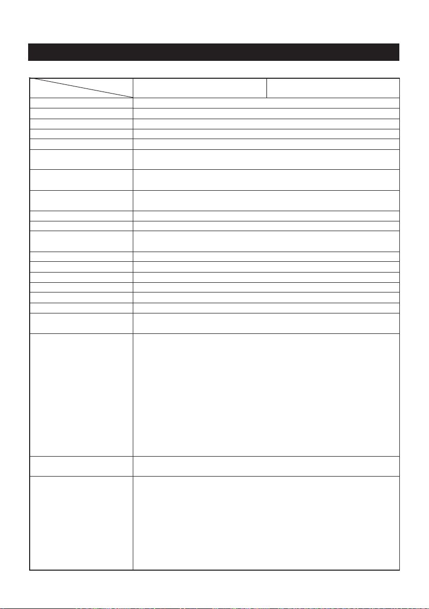
2.2 Basic Specifications
Item
Model
Printing system
Printing width
Dot density
Paper feed pitch
Printing speed
Printing columns and
character size
Line interval
Character types
Character code
Bar code type
Paper
(See Paper Specifications)
Interface
Input buffer
Download characters
Auto-loading
Paper end function
Paper near end function
Printing color
Battery
No. of printable lines
Power save and auto
power off
CBM-272-RF120
CBM-272-PF120
Line thermal dot printing
48 mm (384 dots/line)
8 dots/mm (Width, Length)
0.125 mm
Approx. 11 lines/sec. (At maximum)
32 columns (12 x 24 Font A) 1.25 x 3.00 mm
42 columns (9 x 24 Font B) 0.88 x 3.00 mm
Initial value: 4.23 mm (1/6 inch)
Can be set with a command (1/360 inch at minimum)
Alphanumeric characters, symbols, international characters
(Choose from 10 countries)
Domestic characters, IBM characters #2 (Choose either)
UPC-A/E, JAN (EAN) 13-/8-column, ITF, CODE 39, CODE 128, CODABAR
Thermal paper roll : 58 + 0/- 1 mm x ø83 (max.) mm, 60~75µm thick
Serial (RS-232C), Parallel (CENTRONICS compliant)
2 KB
Font A, B: 95 characters each
Provided (Can be enabled/disabled with the DIP switch)
Provided
Provided (Can be enabled/disabled with the DIP switch)
Capable of printing in two colors (red/black) with the special thermal
paper.
Battery pack: 6HR-AAU-CBM (7.2 VDC, 1650 mA/h)
Ni-MH (pack of 6 AA dry cells, connectable to charger circuit via
connector)
Charging time: Approx. 5.5 hours (to full charge)
Charging monitor: POWER lamp (Red) lit in charging, goes off when
fully charged.
Recharging cycles: Over 300 cycles (at room temperature)
Charger: Built in the CBM-272 Printer.
Charger power supply: Power adapter (27AD)
The printer can be powered while the batteries are charging (floating).
Discharge control: Low voltage alarm=5.9 V, discharge termination
voltage=5.6 V, monitored by signal output and POWER lamp (Green).
Approx. 30,000 lines and more (continuous sliding print of ANK,
standard print density, at room temperature)
To save battery consumption, the printer automatically enters the power
save mode if it receives no print data, or not operated, for approx. 10
minutes. If the same inactive state continues for another 10 minutes, the
auto power off feature automatically turns the printer off. (The timer
intervals can be set with a DIP switch.)
To turn the printer on again, temporarily set the POWER switch to OFF,
then set it back to ON. All data will initialize when the printer repowers.
The power save and auto power off features are left disabled when the
printer is powered from the AC adapter.
CBM-272-RF230
CBM-272-PF230
— 4 —
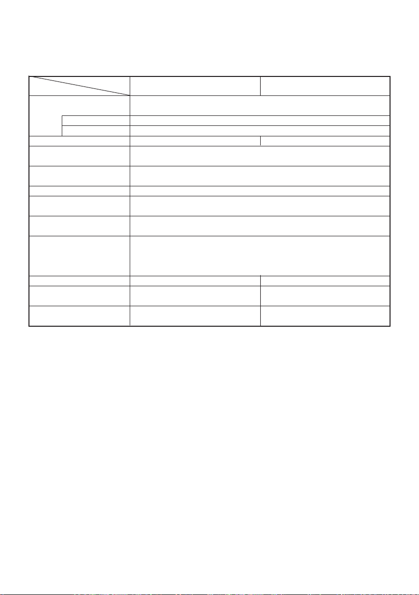
Item
Model
AC adapter
Type
AC cord
Supply voltage
Power consumption
Weight
Outer dimensions
Operating temperature and
humidity
Storage temperature and
humidity
Reliability
EMI *1
Applicable standard
(Main body) *1
Applicable standard
(Power source)
Rated input : 100 ~ 240 V, 50/60 Hz, 40 VA
Rated output : 7.2 V DC, 2 A
27 AD
2-core cord (Depends on the destination)
120 V AC +/– 10%, 60 Hz 230 V AC +/– 10%, 50/60 Hz
At non-printing: Approx. 2 W
At printing: Approx. 15 W (approx. 20 W at maximum)
Main body: Approx. 750 g (Paper roll excluded)
AC adapter: Approx. 350 g
106 (W) x 183 (D) x 126 (H) mm
5 ~ 40°C, 35 ~ 85 % RH (No dew condensation)
–20 ~ 60°C, 10 ~ 90% RH (No dew condensation)
Printing head life: (25°C)
FCC Class-A EN55022 Class-A
UL, C-UL GS, CE Marking
UL, C-UL GS
CBM-272-RF120
CBM-272-PF120
Pulse resistance : 50 million pulses or more (Print rate 12.5%)
Wear resistance : 50 km or more (With recommended thermal paper
at normal temperature and humidity)
*1 indicates the standard satisfied when the AC adapter 27AD is used.
CBM-272-RF230
CBM-272-PF230
— 5 —

2.3 Paper Specifications
2.3.1 Recommended Paper
• Type : Thermal paper
• Paper width : 58 + 0/– 1 mm
• Paper thickness : 60~75µm
• Roll diameter : ø83 mm or less
• Printing surface : Outside of the roll (Surface)
• Recommended paper : TF50KS-E2C (Monochrome) made by NIPPON PAPER or
its equivalent 735 FA (2-color, Black based) made by
RICOH or its equivalent PB670 (2-color, Red based)
made by MITSUBISHI PAPER or its equivalent
• Core : ø12 mm (Inner dia.), (18 mm øOuter dia.)
CAUTION:
• Use of non-specified paper may cause irregularity of print density. If this is the case,
use the DIP switch to reset print density. (See 5. DIP SWITCH SETTING)
• Do not paste the paper to the core.
• If the paper comes in contact with a chemical or oil, it may discolor or lose a record.
• Do not rub the paper surface strongly with a nail or hard metal. It may discolor.
• Discoloring starts at about 70°C. Watch out for effects of heat, humidity, light, and
so on.
— 6 —
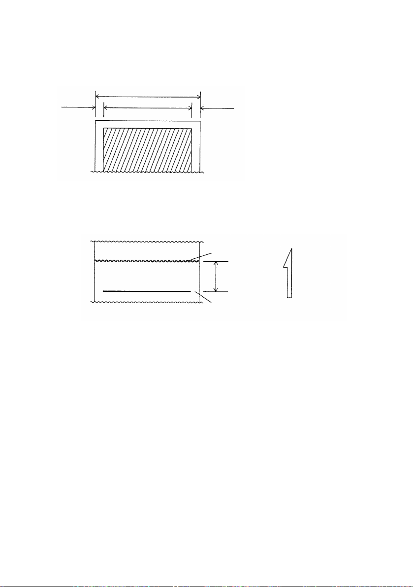
2.3.2 Printing Position
Thermal paper
Paper Width: 58 mm
About 4 mm About 6 mm
Printing Area: 48 mm
2.3.3 Printing Head and Paper Cutter Layout
Paper Cutter Position
About 13.5 mm
Head Position
Paper Feed
Direction
— 7 —
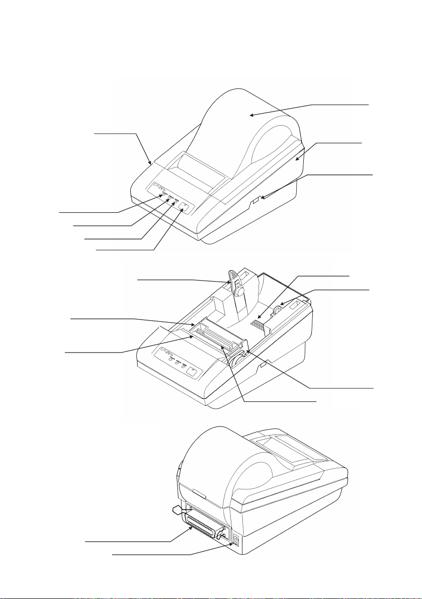
3. OUTER APPEARANCE AND COMPONENT PARTS
(14) Printer Cover
Upper Cover
Bottom Cover
(1) POWER Switch
(2) POWER Lamp
(3) ERROR Lamp
(4) PAPER lamp
(5) FEED Switch
Printer Mechanism
(11) Paper Cutter
(13) Interface Connector
(12) Power Connector
(7) PNE Sensor
(8) DIP Switch
(6) Paper Holder
(10) Head-up Lever
(9) Platen Roller Unit
— 8 —

(1) POWER switch
Turns on/off the power for the printer body.
(2) POWER lamp (Green/Red)
Comes on in green when the POWER switch is set to ON.
This light is lit in red while the battery is charging, and goes off when it is fully
charged up.
(3) ERROR lamp (Red)
Illuminated at the time of a head-up mechanical error, and blinks at the time of
starting a macro.
(4) PAPER lamp (Red)
Illuminated when the paper is running out (when there is little paper left), and
blinks when a label paper cut is specified.
(5) FEED switch
Feeds the paper. It is fed continuously while the switch is held down.
(6) Paper holder
Set the paper roll in this holder.
(7) PNE sensor
Detects that the paper is running out.
(8) DIP switch
Initially sets the printer at power-on and sets the functions.
(9) Platen roller unit
Detach this unit when the paper is jamming or when you clean the head.
(10) Head-up lever
Used when replacing the paper or detaching/reattaching the platen roller unit.
(11) Paper cutter
Cuts the printed paper.
(12) Power connector
Connects to the accessory AC adapter (27AD).
(13) Interface connector
Connects to a communication interface cable. There are two types, for serial
and parallel interfaces.
(14) Printer cover
Detach this cover when replacing the paper.
— 9 —
4. OPERATION
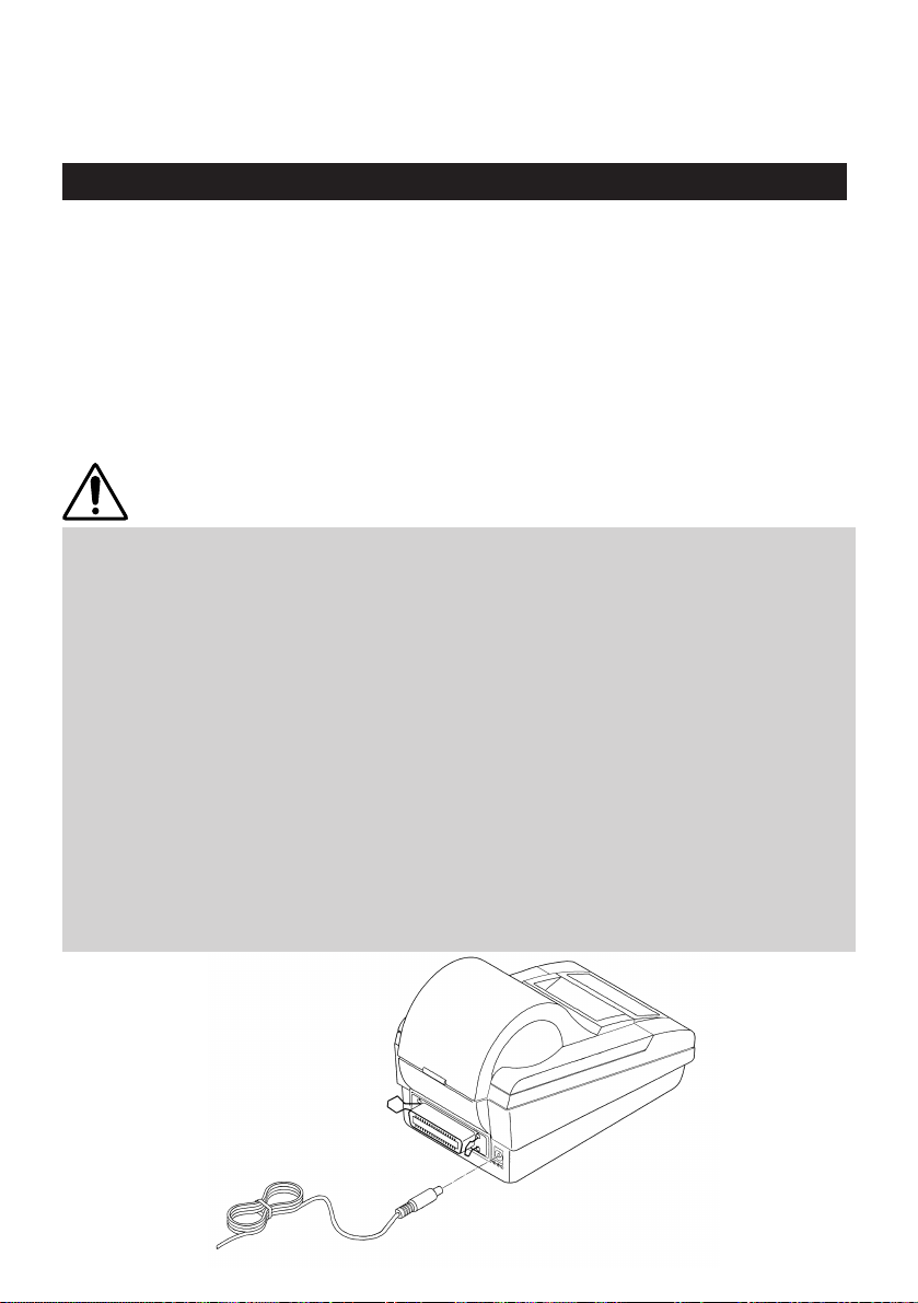
4.1 Connecting AC Adapter
Turn off the power.
1
Connect the cable connector of the AC adapter to the power connector located on
the back of the printer.
2
Connect the AC power cord of the AC adapter, and plug it into a socket.
(For the details of printer status, see “Operation Panel and Display of Error” in
3
Section 4.15.)
CAUTION:
• Use only the specified AC adapter.
• When disconnecting/reconnecting the cable connector of the AC adapter, be sure to
hold the connector.
• Separate the AC adapter from other noise-generating devices.
• Pulling the AC power cord may damage it, resulting in a fire, electric shock, or
snapping.
• If a thunder/lightning storm is nearby, disconnect the AC adapter from the socket
and do not use the printer, because a fire or electric shock may occur.
• Do not put the AC power cord close to a heating device. Its coating can melt and
cause a fire or electric shock.
• Install the printer in a well-ventilated place, because the AC adapter generates heat
when it is used.
• Use the specified AC power source. Connect to a power source with sufficient
capacity. If the capacity is insufficient, a fire may result from heat generation.
• After using the printer or when not using it for a long period of time, be sure to
unplug the AC adapter from a plug socket for your safety.
• Before connectiong the AC adapter be sure to set the POWER switch to OFF.
— 10 —
— 10 —
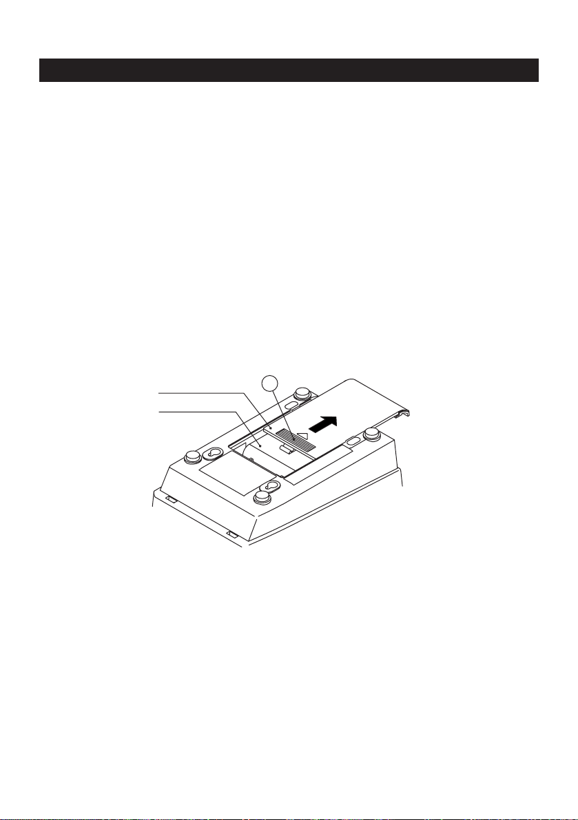
4.2 Replacing the Battery Pack
4.2.1 Removing the Battery Pack
Unplug the AC cord from the wall outlet.
1
Set POWER switch to OFF.
2
Remove the battery cover.
3
(While pressing down section A, slide the battery cover in the direction of the
arrow.)
Remove battery pack from compartment and disconnect its connecter.
4
Battery cover
Battery pack
A
— 11 —

4.2.2 Installing the Battery Pack
With the labeled side of battery pack facing up, connect the battery
connecter.
1
Insert the battery pack into the battery compartment.
(Tuck the battery connecter tidily in the extra space of the compartment.)
2
Place the battery cover back over the compartment by sliding it from the
back of the printer. (Exercise care not to bite the battery leads.)
3
Be sure to install the battery cover after the battery pack is replaced.
4
Label
Battery pack
Battery connecter
CAUTION:
• When connecting or disconnecting the battery connecter, be sure to hold the
connector shells. Never pull the battery leads.
• Do not give the battery pack a severe jolt or drop on a hard surface.
• To prevent the battery pack from bulging, heat build-up, or bursting, never use any
battery pack other than the supplied battery pack.
• Never remove the battery pack from the printer and use it for driving any other
device. Such a practice may cause damage to the battery pack or the target device.
• Be sure to install the battery cover after the battery pack is replaced.
— 12 —

4.3 Charging the Battery Pack
The battery pack can be charged in either non-floating or floating modes. In
floating mode, the battery pack can be charged while the printer is operating.
4.3.1 Non-Floating Charging
Turn off the power.
1
Plug the cable connector of the AC adapter into the power connector at the
2
back of printer.
Connect the AC cord of the AC adapter, and plug the other end to a wall
outlet.
3
(1) The POWER lamp comes on in red, indicating that charging has started.
(2) Charging completes in approx. 6 hours when the POWER lamp goes off.
(Trickle charging continues until the AC cord is unplugged from the wall
outlet.)
(3) Disconnect the AC cord of the AC adapter from the wall outlet.
(4) Set the printer's POWER switch to ON. The POWER lamp will come on in
green, indicating that the printer is ready.
4.3.2 Floating Charging
Turn off the power.
1
Connect AC cord of the AC adapter, and plug the other end to a wall outlet.
2
Set printer's POWER switch to ON. The POWER lamp will light in green. Now
you can use the printer while charging the battery pack. (Charging conditions
3
are identical to those in non-floating mode.)
— 13 —

4.3.3 Battery-Powered Operation
The printer is powered only from the battery pack if the AC adapter is left
disconnected. The printer is ready to be run by the battery when its POWER
switch is pressed ON (POWER lamp lit in green). Be sure to press the POWER
switch OFF (POWER lamp goes off) after every use.
Protecting the Battery Pack
(1) If the battery voltage drops to around 5.9 V, the POWER lamp starts blinking in
green to indicate low voltage. The printer can deliver a low voltage alarm to
an external device (by setting DIP switch1-5).
(2) If the battery voltage drops further to around 5.6 V, the printer is automatically
turned off.
(3) If the printer is powered up again, the POWER lamp will either come on or
start blinking in green (in Standby mode). If printing resumes, the printer will
shut down soon again due to low battery voltage.
* In the case of (1) or (2) above, the battery pack requires recharging.
Low Voltage Signal
If the battery voltage drops to 5.9 V while in battery-powered operation, the printer
can deliver a low voltage signal.
(1) Serial interface → Sends a DTR indicating low voltage.
DIP switch1-5
OFF = Send no DTR.
ON = Send DTR.
(2) Parallel interface → Sends a SELECT (L) indicating low voltage.
DIP switch1-5
OFF = Send no SELECT.
ON = Send SELECT.
Power Save and Auto Power Off Features
(1) If the printer receives no print data from the host, or not operated, for a set
time period, it enters power save mode to reduce unnecessary battery
consumption. (The timer is set to 10 minutes by default. It can be set with a
DIP switch.)
POWER lamp’s luminance in green is reduced to a half, indicating that the
printer is in power save mode.
(2) If the power save mode continues for another 10 minutes, the auto power off
feature automatically turns the printer off.
(3) The printer can be repowered by cycling the POWER switch.
— 14 —

4.3.4 Battery Voltage Check
If the battery voltage drops below 5.6 V, the voltage check feature automatically
shuts off the printer (POWER switch is left at ON). While the printer may be
repowered by cycling the POWER switch, the battery pack will require recharging
at this point.
The voltage check feature is more likely to activate in print mode than standby
mode. It activates the battery pack protection circuit and shuts off battery power
supply.
CAUTION:
• While the battery pack is charging, the battery cover will become slightly hot. This
will cause no problem.
• If the battery cover becomes too hot (50°C or above) while charging, immediately
unplug the AC cord from the outlet and call your dealer.
• Charging efficiency depends significantly on the ambient temperature. The most
efficient temperature range is from 10°C to 30°C. It is recommended you charge the
battery pack within this optimum range.
• To prevent possible electrolyte leakage, do not leave the battery pack connected to
the printer for a long time period. Also be sure to turn the printer power off after
every use.
• Be sure to recharge the battery pack before using the printer 1) for the first time after
purchase or 2) again after remaining idle for more than 3 months. The battery pack
will also self-discharge during extended periods of storage. It is recommended you
recharge the battery pack every 3 to 6 months.
• If the battery pack is recharged after the printer is left unused for more than 3
months, the charging cycle may terminate before the battery pack is fully charged
up. In such a case, repeat the charging/discharging cycle several times.
• After the battery pack is taken out of low-temperature (0°C or below) or hightemperature (40°C or above) storage, do not use it until its temperature falls within
the operating range and stabilizes. Otherwise, you may encounter problems with low
voltage or lowered performance.
• Do not attempt to modify the built-in battery charger in the printer. It should only be
used for charging the supplied battery pack. To prevent the battery pack from
bulging, heat build-up or bursting, only charge with the supplied battery pack
charger.
• Charge the battery pack with the dedicated built-in charger and within the specified
charging time.
Running the battery pack through repeated partial charge and drain cycles may cause
a gradual reduction of return power called “memory effect” that shortens battery
life.
• If the printer or its internal battery pack shows any sign of electrolyte leakage,
discoloration, deformation, or odd smell, immediately stop using the printer. Then
call your dealer.
— 15 —

CAUTION:
• If a charging cycle does not complete within the specified time, stop charging at that
point. This will help prevent electrolyte leakage, heat build-up, or bursting.
• The battery pack has a limited life. If charging cycle time is significantly shortened
although the specified charging requirements are satisfied, it is most likely that the
battery life has expired. Replace it with a fresh one.
• To prevent the battery pack from lowered performance or low voltage, do not leave
the printer power turned on for a long time period.
• Do not attempt to charge the battery pack when not connected to the printer.
• Due to its electrochemical nature, battery pack performance gradually degrades as
a result of long-term storage and repeated use.
• Due to memory effect, the battery pack may not fully charge when plenty of energy
still remains in it. Fully discharge the battery by printing before recharging again.
• If the battery pack only provides very short operating performance, its battery life
has most likely expired.
— 16 —

4.4 Reset
4.4.1 Reset during a Printing Task
The printer, when operating on battery power, may reset (POWER lamp goes off)
while it is printing dense patterns or images. This is because the battery voltage
drops below 5.6 V due to dense pattern, tripping the battery protection circuit. This
phenomenon is more likely to occur after the battery voltage starts dropping. If the
printer resets too frequently despite this action, recharge the battery pack.
4.4.2 Voltage Drop
Battery voltage drop increases with the number of simultaneously active dots,
which makes the printer more likely reset. This phenomenon is likely to occur in
battery-powered operation.
Increased print density may be another cause of frequent reset because it extends
strobe length although the number of active dots is not affected. (default print
density is at standard level). In particular, reset can occur when printing under low
temperature conditions.
— 17 —

4.5 Power Save and Auto Power Off
To save unnecessary battery consumption, the printer automatically enters the
power save mode if it receives no print data, or is not operated, for approx. 10
1
minutes. If the same inactive state continues for another 10 minutes, the auto
power off feature automatically turns the printer off. (The timer intervals can be set
with a DIP switch.)
No data, no operation (variable)↓Power Save (fixed to 10 min.)
↓
↑
Auto Power Off
• Can be set with a DIP switch.
• The auto power off feature is inactive when the head-up lever is pulled up or, PE/
PNE feature is active.
(1) Serial interface
DS2
5
OFF
ON
OFF
ON
6
No data, no operation
OFF
OFF
ON
ON
10 min.
20 min.
30 min.
Power Save
No time limit
↑
10 min.
↑
↑
Auto Power Off
NO
YES
No data, no operation for 10 min.
↑
No data, no operation for 20 min.
↑
No data, no operation for 30 min.
Remarks
Auto Power Off is inactive.
• By default, DS2-5 and DS2-6 are set to ON and OFF, respectively.
• “No data“ means that no print data is being sent from the host to the printer.
• “No operation“ means that neither the FEED switch nor the head up lever on the
printer is operated.
• The printer enters the normal mode from the power save mode when its FEED
switch or head up lever is operated or power is applied from the AC adapter to
the printer's DC IN port.
(2) Parallel interface
DIP switches DS2-1 and DS2-2 are used for parallel interface.
To repower the printer after it is turned off by auto power off, temporarily set its
POWER switch to OFF, then set it back to ON. At this time all data will initialize.
2
The power save or auto power off feature is disabled when the printer is powered
from the AC adapter.
3
— 18 —

4.6 Connecting Interface Cable
Turn off the power. (Mating side included)
1
Check the top and bottom of cable terminals, and connect to the interface
connector.
2
Fix the cable terminals. Serial interface : Tighten screws, to fix it.
3
Connect the cable to the host computer.
Parallel interface : Turn a stopper, to fix it.
4
CAUTION:
• Referring to "6. PARALLEL INTERFACE" and "7. SERIAL INTERFACE," check the pin
configuration of the interface connector and cable. Wrong wiring could cause
trouble or malfunctioning to not only the printer body but also the host computer.
• When disconnecting/reconnecting the interface cable, be sure to hold the connector.
Pulling the cable itself may snap the internal wires.
• Connect the interface cable securely. Otherwise, communications may not be
obtained due to a connection failure.
— 19 —

4.7 Inserting the Paper
CAUTION:
• Be sure to use the specified paper roll.
• Use of non-specified paper may not guarantee the print quality, printing head life,
and so on.
Hold the convexity on the rear of the printer cover, and raise it upward.
1
Cut the front end of the paper roll almost at a right angle.
2
CAUTION:
• The printer cover is not stationary (Opening/Closing). After detaching it, be careful
not to lose or break it.
• Do not insert a ragged or dog-eared end of the paper roll, because it could result in a
paper jam or insertion error.
Good Good Good No Good No Good No Good
Make sure that the power is turned on.
3
Pull the head-up lever to this side to raise up the printing head.
4
If there is still some paper remaining after a paper-out indication, eliminate the
paper roll according to “4.8 How to Remove Remaining Paper Roll.”
5
Insert the front end of the paper roll straight into a paper insertion slot.
6
Set the paper roll firmly in the paper holder.
7
— 20 —

Put back the head-up lever. The paper roll is automatically pulled in by the platen
roller to feed a constant amount of paper. (When auto-loading is enabled.)
8
Put back the printer cover.
9
CAUTION:
• If the paper roll is still slack, rewind the paper to remove the slack.
• If the paper roll is tilted, raise the head-up lever to correct the paper roll position, or
pull out the paper roll and set it again.
• Do not open the printer cover while printing.
• Do not hold or press the paper roll while printing, because it could cause a paper
jam.
• After the paper is set, the printer is made ready to start printing. Note that if data is
remaining in the buffer, the printer will start printing after the paper is set.
• Do not run the printer with its cover removed, because it could cause
malfunctioning or an irregularity of the sensor.
— 21 —

4.8 How to Remove Remaining Paper Roll
Remove the printer cover.
1
Raise the head-up lever.
2
Gently pull out the paper to the near side. If the paper roll is still remaining, cut it
just before the paper insertion slot before pulling it out.
3
CAUTION:
• Do not pull out the paper roll in the opposite direction.
• Never take out paper with the head-up lever lowered, because it could damage the
printing head.
• The printer mechanism may be very hot just after printing, so be duly careful.
— 22 —

4.9 Eliminating the Paper Jam
Turn off the power.
1
Detach the printer cover.
2
Cut the paper roll near the paper insertion slot.
3
Raise the head-up lever.
4
Raise the blue levers located on both sides of the platen roller unit, to gently
detach the unit. The platen roller unit can be detached by manually raising the
5
blue levers.
Remove the remaining paper roll completely from the paper passage.
6
Confirming the direction of the platen roller unit, reattach it to the mechanism.
7
Shift down the blue levers on both sides, to fix the unit.
Lower the head-up lever.
8
— 23 —

CAUTION:
• Do not carry out this work just after printing because the printing head is very hot.
• Be sure to turn off the power when detaching the platen roller unit.
• When eliminating remaining paper, do not touch the heating surface of the head with
a bare hand or metal piece.
• Do not detach the platen roller unit unless necessary, such as for a paper jam.
• When putting back the platen roller unit, be sure to confirm that it is correctly
reattached.
• Never detach or reattach the platen roller unit with the head-up lever lowered.
4.10 FEED Switch Function
4.10.1 When Thermal Paper is Used
Pressing the switch, feed the paper by 1 line. If the switch is held down, the paper
will be fed continuously.
4.10.2 When the Macro is Executed
If the ERROR lamp is blinking while waiting for execution of a macro, press the
FEED switch. The waiting state continues until the switch is pressed.
4.11 Paper End Function
If the printing paper runs out, the parallel interface will output BUSY, FAULT, and
PE to the host, and the serial interface will output DTR to stop printing,
respectively. If some data are still remaining in the buffer, printing will be resumed
after replacing the paper. Replace the paper according to “4.7 Inserting the Paper.”
After replacing the paper, cancel BUSY (DTR), FAULT, and PE outputs. For details,
see “4.12 Paper Near End Function.”
— 24 —

4.12 Paper Near End Function
If the paper is running out, the PNE sensor informs the host computer that the
paper is running out, by means of a signal output or the PAPER lamp on the panel.
The PAPER lamp is illuminated unconditionally.
If the PNE sensor detects that the paper is running out, the PAPER lamp will be
illuminated.
1
If PNE is enabled, the parallel interface will output PE. (At initial setting)
2
Printing is allowed up to about 1.5 m. (Initial value) After printing or feeding the
paper by a specified amount, the parallel interface will output BUSY and FAULT,
3
and serial interface will output DTR to stop printing, respectively.
Replace the paper according to the procedure in “4.7 Inserting the Paper.”
4
After replacing the paper, cancel the BUSY (DTR), FAULT, and PE outputs.
5
(1) The following lists the outputs made by the near paper end function and the
paper end function. The output state can be changed by the DIP switch or a
command.
DS1-1
State
OFF
*Mark : Default setting
PNE : Paper Near End
PE : Paper End
ON
PNE
Function
Disabled
Enabled
PE Signal Output Setting
When PE is selected*
When PNE is selected
When PE is selected
When PNE is selected*
by Command
PE Output
When PE is detected*
When PNE is detected
When PE is detected
When PNE is detected*
— 25 —
BUSY (DTR)/
FAULT Output
When PE is detected*
When PE is detected
When printing stops
due to PNE*
When printing stops
due to PNE
PAPER
Lamp
At PNE*
At PNE
At PNE
At PNE*

(2) Print amount after detecting PNE
When PNE is enabled, a printable amount after PNE detection can be adjusted.
PNE is detected when the remaining amount of the paper roll is about 2~3 m.
(It depends on the paper quality used, paper thickness, and operating
environment.)
An initial value is 1.5 m. Up to 1.5 m can be printed after detecting PNE. At
this time, with the approx. 70µm-thick recommended paper, the remaining
amount of the paper will be about 0.5~1.5 m when printing stops.
It can be adjusted between 0 and 2.55 m with a command. Adjust it
depending on the operating environment and paper quality.
Depending on an adjustment value, paper end may be detected (Printing stop)
first.
If PNE is detected at power-on, a set amount of printing will be done from that
point. (The default is 1.5 m)
— 26 —

4.13 Auto-Loading Function
This printer has a function to automatically set the paper. If the paper end sensor,
near paper end sensor, and head-up lever are cancelled, the paper will be
automatically fed by a constant amount in about 1 second.
In order to smooth operation, cancel the head-up mechanism last.
Also, you can use the DIP switch to enable/disable the function. If disabled, autoloading will not be performed.
CAUTION:
• When auto-loading is being activated, do not touch the paper roll, because it could
result in a paper feed failure or cause the paper to be one-sided.
• Be sure to set the paper until it comes into contact with the platen roller; otherwise,
the paper cannot be fed and the printing head could be damaged.
4.14 Self-Print Function
This printer has a function to perform preset printing. Turn on the power with the
FEED switch held down. It will print the ROM version, DIP switch state, characters
used, kanji, etc. After self-printing is completed, the printer restores its normal
operating conditions.
CAUTION:
• Do not use this function when the paper roll is running out.
• Data communication cannot be done during self-printing.
— 27 —

4.15 Operation Panel and Display of Error
1. POWER lamp (Green/Red)
The POWER lamp indicates printer status with 2 colors.
(1) When powered by AC adapter (battery pack is charged in floating mode)
Item
Charging
battery pack
Floating
charging
Status
Charging
Fully charged
Printing
Charging
Fully charged
POWER
Switch
OFF
OFF
ON
ON
POWER
Lamp
(Green)
Off
Off
Lighting
Lighting
POWER
Lamp
(Red)
Lighting
Off
Off
Off
(2) When powered by battery pack (AC adapter disconnected)
Item
Battery
powered
Power Save
or Auto
Power Off
Status
Non-
operation
Printing
Below 6.5 V
Below 6.0 V
No data, no
operation
Power Save
Auto Power
Off
POWER
Switch
OFF
ON
ON
ON
ON
ON
ON
POWER
Lamp
(Green)
Off
Lighting
Blinking
Off
Lighting
Lighting at
half
luminance
Off
POWER
Lamp
(Red)
Off
Off
Off
Off
Off
Off
Off
Timer set with DIP switch
Timer fixed to 10 min, and
POWER lamp (Green)
lights at half luminance.
*If the printer turns off with auto power off, it can be repowered by cycling the
POWER switch.
Remarks
Trickle charging
Remarks
Low Voltage signal
(10/20/30 min.)
— 28 —

2. ERROR lamp (Red), PAPER lamp (Red)
Indicates an error by illuminating or blinking the lamps.
Error
ERROR Lamp
Display
PAPER Lamp
Reset
Memory check error
Head-up
Head overheat
Paper near end
Paper end
Macro execution wait
Quick blinking
ON
Blinking
OFF
OFF
Slow blinking
OFF
OFF
OFF
ON
ON
OFF
Cannot be reset
Lower the head-up lever.
Automatically reset by a
temperature drop
Set a new paper roll after a
print stop.
Set a new paper roll.
Press the FEED switch.
<Error Details>
Head-up ----- Occurs when the head-up lever is raised. The printer cannot
feed the paper or print. The parallel interface outputs BUSY
and FAULT, and serial interface DTR, respectively.
Head overheat ----- If the temperature of the printing head rises (About 65°C or
more), in order to protect it against overheating, a printing
head temperature sensor will be activated to stop printing.
The parallel interface outputs BUSY and FAULT, and serial
interface DTR, respectively. If the temperature drops (About
60°C), printing will be automatically resumed.
Paper near end ----- If the diameter of the paper roll decreases, the paper near
end sensor will react to inform you that the paper roll is
running out. See “4.12 Paper Near End Function”.
Paper end ----- If the paper roll runs out, the paper sensor near the printing
head will react to stop printing. See “4.11 Paper End
Function”.
— 29 —

4.16 Red/Black Print (Precautions for Use)
(1) Types of paper
The red and black two-color thermal paper changes its colors by controlling
the energy applied to the thermal head. It is largely divided into two types,
depending on the color development order. Select either of them to suit your
application.
1. Red-based two-color thermal paper (PB670: MITSUBISHI PAPER)
Red print (low energy) → Black print (high energy)
2. Black-based two-color thermal paper (735FA: RICOH)
Black print (low energy) → Red print (high energy)
(2) High-energy printing rate
High-energy print (black print on red-based paper, or red print on black-based
paper) required the application of high energy to the thermal head. To protect
the service life of the thermal head, use the following printing ratio as a
guideline. Also use the default printing rate.
1. Continuous print of high-energy print only : 6 % or less
2. Mixed continuous print of low-energy and high-energy print
: 30 % or less of the
standard printing rate of
12.5 %
3. Printing rate per dot line : 50 % or less
(3) Minimum dots for high-energy print
When high-energy print is used, the recommended minimum area is 3 dots
(length) x 3 dots (width) or more. Depending on the set printing density, the
paper used, or the printing characters, a sufficient change of color tone may
not be obtained even by high-energy print.
(Characters such as [, !, ', (, i, -, font B with small dot matrix)
It is recommended to use in such printing patterns as double-width characters,
double-height characters, double-width and -height characters.
CAUTIONS
• If high-energy print is continuously carried out at a high operating ambient
temperature, the thermal head will become hot more quickly and the protective
circuit will be activated, to stop printing more frequently.
Fully consider the working temperature and printing rate.
• If a bar code is printed on the two-color paper, both colors may appear in normal
print and high-energy print, or the bar code may not be correctly read by a bar code
reader. Be fully aware of this when using the two-color paper.
• Do not perform high-energy print on the single-color paper (regular thermal paper).
It may deteriorate the service life of the thermal head or the printing quality.
• For setting, see Commands (DC3: Switching the Red/Black Printing).
— 30 —

5. DIP SWITCH SETTING
5.1 Location of DIP Switch
Turn off the power.
1
Detach the printer cover, and take out the paper roll. (The switch is found under the
paper roll.)
2
There are 2 switches (8-pole and 4-pole) for the serial interface, and 2 switches (8pole and 4-pole) for the parallel interface.
3
5.2 DIP Switch Function
DS1 ( For Serial Interface/Parallel Interface)
No.
1
2
3
4
5
6
7
8
Table1
DS1-3
DS1-4
*DS1-5: DTR signal for the serial interface
*DS1-7: Enabled only for the serial interface. Disabled for the parallel one.
Function
PNE selection
CR switching
Print density
Low Voltage signal
Auto-loading
DTR/DSR, XON/XOFF
Kanji code selection
Light
OFF
OFF
SELECT signal for the parallel interface
Standard
ON
Enabled
LF operation
Enabled
Enabled
XON/XOFF
S-JIS
ON
OFF
See Table 1
Slightly Dark
OFF
ON
OFF
Disabled
Ignored
Disabled
Disabled
DTR/DSR
JIS
Dark
ON
ON
Upon Shipment
ON
OFF
ON
OFF
OFF
ON
OFF
OFF
— 31 —

DS2 (Serial Interface)
No.
1
2
3
4
5
6
7
8
Table2
DS2-4
Function
Baud rate and parity
Power save and auto
power off features
Not used
Not used
DS2-3
OFF
OFF
OFF
OFF
OFF
OFF
OFF
OFF
ON
ON
ON
ON
ON
ON
ON
ON
OFF
OFF
OFF
OFF
ON
ON
ON
ON
OFF
OFF
OFF
OFF
ON
ON
ON
ON
DS2-2
OFF
OFF
ON
ON
OFF
OFF
ON
ON
OFF
OFF
ON
ON
OFF
OFF
ON
ON
ON
—
—
See Table2
See Table3
DS2-1
OFF
ON
OFF
ON
OFF
ON
OFF
ON
OFF
ON
OFF
ON
OFF
ON
OFF
ON
OFF
—
—
Parity
None
None
None
None
None
None
Odd
Odd
Odd
Odd
Odd
Even
Even
Even
Even
Even
Upon Shipment
OFF
OFF
OFF
OFF
ON
OFF
OFF
OFF
Baud Rate
9,600 bps
1,200
2,400
4,800
9,600
19,200
1,200
2,400
4,800
9,600
19,200
1,200
2,400
4,800
9,600
19,200
Table3
DS2-5
OFF
ON
OFF
ON
No data, No operation
DS2-6
OFF
OFF
ON
ON
10 min.
20 min.
30 min.
Power Save
No time limit
↑
10 min.
↑
↑
— 32 —
Auto Power Off
NO
YES
↑
↑
Remarks
Auto Power Off is inactive.
No data, no operation for 10 min.
No data, no operation for 20 min.
No data, no operation for 30 min.

DS2 (Parallel Interface)
No.
1
2
3
4
Table4
DS2-1
OFF
ON
OFF
ON
Function
Power save and auto
power off features
Not used
Not used
No data, No operation
DS2-2
OFF
OFF
ON
ON
10 min.
↑
20 min.
30 min.
ON
See Table4
—
—
Power Save
No time limit
10 min.
↑
↑
OFF
—
—
Auto Power Off
NO
YES
↑
↑
Upon Shipment
ON
OFF
OFF
OFF
Remarks
Auto Power Off is inactive
No data, no operation for 10 min.
No data, no operation for 20 min.
No data, no operation for 30 min.
— 33 —

5.3 Jumper Wire Function
The jumper wires have been set at shipment. The following lists the basic settings
at shipment. Check the settings by performing self-printing.
Jumper Wires
No.
J1
J2
J3
J4
J5
J6
J7
J8
Communication error mark
Function
International character
Data bit length
Unused
↑
Unused
Short
See Table 5
7 bits
—
—
—
Ignored
Open
8 bits
—
—
—
“?” printed
*J4: Serial interface only. Disabled for the parallel one.
*J5 ~ J7: Do not change the shipment settings.
Table 5
No.
J1
J2
J3
USA
Short
Short
Short
France
Open
Short
Short
Germany
Short
Open
Short
U.K.
Open
Open
Short
Denmark-I
Short
Short
Open
Sweden
Open
Short
Open
CAUTION:
• Never change the settings of the jumper wires.
• If you want to change their settings, consult us.
• Never disassemble the printer body. It could cause trouble, etc.
Upon Shipment
Short
Short
Short
Open
Open
Open
Open
Open
Italy
Short
Open
Open
Japan
Open
Open
Open
— 34 —

6. PARALLEL INTERFACE
6.1 Specifications
• Data input system : 8-bit parallel (DATA1 to DATA8)
• Control signals : ACK, BUSY, STROBE, FAULT, SELECT, PE, RESET
• Applicable connectors : Printer side : 57LE-40360 (Anphenol) or its equivalent
Cable side : 57-30360 (Anphenol) or its equivalent
6.2 Connector's Pin Configuration
No.
1
2
3
4
5
6
7
8
9
10
11
12
13
14
15
16
17
18
Signal Name
STROBE
DATA 1
DATA 2
DATA 3
DATA 4
DATA 5
DATA 6
DATA 7
DATA 8
ACK
BUSY
PE
SELECT
GND
FRAME GND
No.
19
20
21
22
23
24
25
26
27
28
29
30
31
32
33
34
35
36
Signal Name
TWISTED PAIR GND
↑
↑
↑
↑
↑
↑
↑
↑
↑
↑
↑
RESET
FAULT
GND
— 35 —

6.3 Input and Output Signals
6.3.1 Input and Output Signals
(1) Input signals to the printer
• DATA : 8-bit parallel signal (Positive logic)
• STROBE : Strobe signal to read the 8-bit data (Negative logic)
• RESET : Signal to reset the entire printer (Negative logic); 1 ms or more
(2) Output signals from the printer
• ACK : 8-bit data request signal. A pulse signal to be output at the end
of the BUSY signal (Negative logic)
• BUSY : Signal to indicate that the printer is busy. Input new data when
it is “Low.” (Positive logic)
• FAULT : Turned to “Low” when the printer has an alarm. At this time, all
the control circuits in the printer stop. (Negative logic)
• PE : Output if the printing paper has run out or is running out.
(Positive logic)
• SELECT : Set to “Low” if low voltage occurs (set with DSW1-5).
(3) Power source and the related
• GND : Common ground for the circuits
6.3.2 Electrical Characteristics
(1) Input signal level
All the input signals are at the CMOS level.
High level --- 4.0 V at minimum
Low level --- 1.0 V at maximum
(2) Output signal level
All the output signals are at the CMOS level.
High level --- 4.5 V at minimum
Low level --- 0.1 V at maximum
(3) Input and output conditions
The STROBE and RESET input signals are pulled up at 10 kΩ, and the other
input signals at 50 kΩ , respectively.
[Printer Side] [Host Side]
All the output signals are pulled up at 50 kΩ. (except SELECT signal)
Vdd
Twist Pair Wire
— 36 —

[Printer Side] [Host Side]
Vdd
Twist Pair Wire
6.3.3 Timing Chart
Data Input and Print Timings
Power
DATA
STB
T6
BUSY
ACK
T5
T2
T1 T3
T4
T1, T2, T3 0.5 µs MIN
T
4 270 ns MAX
5 2.3 µs TYP
T
T
6 500 ms MIN (At power-on)
6.3.4 Data Receiving Control
The data can be received from the host when the BUSY signal is at “Low,” but
cannot be received when it is “High.”
6.3.5 Buffering
The host side is immediately freed, because 2 KB data can be buffered.
— 37 —

7. SERIAL INTERFACE
7.1 Specifications
(1) Synchronous system : Asynchronous
(2) Baud rate : 1,200, 2,400, 4,800, 9,600, 19,200 bps (Selected by the
user)
(3) 1-word configuration
Start bits : 1 bit
Data bits : 8 bits or 7 bits (Setting upon shipment)
Parity bits : Odd, even, or no parity (Selected by the user)
Stop bits : 1 bit or more
(4) Signal polarity
RS-232C
• Mark = Logic "1" (–3 ~ –12 V)
• Space = Logic "0" (+3 ~ +12 V)
(5) Received data (RXD signal)
• Mark = 1
• Space = 0
(6) Reception control (DTR signal)
• Mark : Data not transferable
• Space : Data transferable
(7) Transmission control (TXD signal)
• DC1 code(11H) X-ON : Data receivable
• DC3 code(13H) X-OFF : Data not receivable
7.2 Connector's Pin Configuration
No.
1
7
3
20
2
6
Signal Name
FG
GND
RXD
DTR
TXD
DSR
Input/Output
Input
Output
Output
Input
— 38 —
Function
Frame Ground
Signal Ground
Received Data
Printer BUSY Signal
Transmitted Data
Data Set Ready

[Note] 1. The RS-232C signals are based on the EIA RS-232C.
2. The received data should be always maintained in the Mark status when
no data is being transferred.
Applicable connectors (D-Sub connectors)
Printer side : 17LE-13250 (Anphenol) or its equivalent
Cable side : 17JE-23250 (Anphenol) or its equivalent
7.3 Input and Output Signals
7.3.1 Input and Output Signals
(1) RXD
Serial received data signal. If a framing error, overrun error, or parity error
takes place, the relevant data will be printed as “?”.
(2) DTR
Write the data or a command when this signal is Ready. If you write at Busy,
the previous data will be ignored, resulting in an overrun error. The data can
be written in the input buffer even during printing. BUSY also occurs at power
on, during test print, in Online mode, on reset, or in low voltage state (selected
with DS1-5).
(3) TXD
If the remaining capacity of the input buffer comes to 128 bytes or less while
receiving the data, DC3(13H) will be output as a data not receivable signal. If
the remaining capacity comes to 256 bytes or more, DC1(11H) will be output
to the host side as a data receivable signal.
When sending the status information, it is confirmed that DSR is a space prior
to sending the data, if DTR/DSR control has been selected. If DTR/DSR control
has not been selected, the data will be sent, ignoring the DSR signal.
(4) FG
Ground for the case
(5) GND
Common ground for the circuits
— 39 —

7.3.2 Data Configuration
Mark
b
, b1, b2, ....
0
t
Space
(1) (2) (3)
(1) Start Bit
(2) Data Bit (+ Parity Bit)
(3) Stop Bit (1 or More)
(1) Start bit
The system reads the status again after a lapse of 1/2 bit from a fall edge from
the mark to space, and if it is a space, this bit will be recognized as the start
bit.
If it is a mark, the system will not recognize the bit as the start bit and try to
detect the start bit again without judging it as an error.
(2) Data bits + Parity bit
The system samples the data bits and parity bit for the 1 bit worth of time
from 1/2 start bit and assumes the then status as the data for the relevant bits.
The bits are called Bit 0, Bit 1, ..., Parity bit, counting from the one closest to
the start bit.
(3) Stop bit
The stop bit is the Mark level of 1 bit or more. If a space is detected in
detecting the stop bit, a framing error will result.
7.3.3 Error Detection
The system detects a parity, framing, or overrun error. If an error is detected, the
relevant data will be stored in the buffer as “?”.
(1) Parity error
With a parity check specified, if an error is detected at parity check time, the
relevant data will be stored in the buffer as “?”.
(2) Framing error
This error results if the Space status is detected at stop bit detection time. The
relevant data will be stored in the buffer as “?”.
(3) Overrun error
If an overrun error is detected, the relevant data will be stored in the buffer as
“?”.
— 40 —

7.3.4 Data Receiving Control
If DTR/DSR control has been selected, the data from the host side will be received
when the BUSY signal is at “Low,” but not received when at “High.” If DTR/DSR
has not been selected, the data from the host side will be received after sending
XON, but not after sending XOFF.
7.3.5 Buffering
To transfer the data to the input buffer, there are two control signals available: DTR
signal and TXD signal. The host side is immediately freed, since the data can be
buffered up to 2 KB.
(1) DTR signal (See 7.3.1-(2))
(2) TXD signal (See 7.3.1-(3))
7.3.6 Electrical Characteristics
RS-232C Circuit
Input (RXD, DSR)
[Printer Side] [Host Side]
Mark=(–8V): Stop bit
RXD
Space=(+8V): Start bit
Equivalent to MAX232
Output (TXD, DTR)
[Printer Side] [Host Side]
Equivalent to MAX232
Mark=(–8V): 1
TXD
Space=(+8V): 0
— 41 —
Mark=(–8V): At Busy
DTR
Space=(+8V): At Ready

8. POWER CONNECTOR
This connector is to supply the power from the special AC adapter(27AD).
Connector Schematic
No.
1
2
12
Function
7.2V
GND
Inner terminal : Minus Pole (GND)
Outer terminal : Plus pole
Jack used : HEC0470-01-640 (HOSHIDEN) or its equivalent
Applicable plug : JXP series type A (I.D.: 2.45 mm, O.D.: 5.5 mm) (HOSHIDEN)
or its equivalent
CAUTION:
• Be sure to use the specified AC adapter. Use of any other power source could cause
trouble to or break the printer.
• Do not connect the power source with different polarity.
• If the printer will not be used for a long period of time, unplug the power plug from
the wall outlet.
— 42 —

9. MAINTENANCE AND SERVICE
For the information on maintenance and service, please contact our dealer or at
the following address.
North America Other Areas
CBM America Corporation Japan CBM Corporation
Service Center Information Systems Division
363 Van Ness Way CBM Bldg., 5-68-10,Nakano
Suite 404 Nakno-ku, Tokyo 164-0001
Torrance, CA 90501, U.S.A Japan
TEL +1-310-781-1460 TEL +81-3-5345-7540
FAX +1-310-781-9157 FAX +81-3-5345-7541
E-mail sales@cbma.com E-mail info-sys@jcbm.co.jp
http://www.cbma.com http://www.jcbm.co.jp
— 43 —

10. PRINT CONTROL FUNCTIONS
10.1 Command List
1
2
3
4
5
6
7
8
9
10
11
12
13
14
15
16
17
18
19
20
21
22
23
24
25
26
27
28
29
30
31
Command
HT
LF
CR
ESC SP
ESC !
ESC %
ESC &
ESC *
ESC –
ESC 2
ESC 3
ESC =
ESC @
ESC D
ESC E
ESC G
ESC J
ESC R
ESC V
ESC a
ESC c 3
ESC c 5
ESC d
ESC i
ESC m
ESC n
ESC t
ESC v
ESC {
ESC $
ESC \
Function
Horizontal tab
Printing and paper feed
Print
Setting the right spacing of the character
Collective Specifying the printing mode
Specifying/Canceling download character set
Defining download characters
Specifying the bit image mode
Specifying/Canceling underline
Specifying 1/6-inch line feed rate
Setting line feed rate of minimum pitch
Data input control
Initializing the printer
Setting horizontal tab position
Specifying/Canceling highlighting
Specifying/Canceling double printing
Printing and feeding paper n/203 inch
Selecting the international character set
Specifying/Canceling 90°-right- turned
characters
Aligning the characters
Selecting the paper near end sensor valid for
a paper end signal output
Enabling/Disabling the panel switches
Printing and feeding the paper by n lines.
NOP
NOP
Setting a remaining amount of printout
Selecting the character codes table
Transmitting the printer status
Specifying/Canceling the inverted characters
Specifying the absolute positions
Specifying the relative positions
Code
09H
0AH
0DH
1BH 20H n
1BH 21H n
1BH 25H n
1BH 26H s n m [a p1
p2... ps x a] m-n+1
1BH 2AH m n1 n2
[d]k
1BH 2DH n
1BH 32H
1BH 33H n
1BH 3DH n
1BH 40H
1BH 44H [n]k 00H
1BH 45H n
1BH 47H n
1BH 4AH n
1BH 52H n
1BH 56H n
1BH 61H n
1BH 63H 33H n
1BH 63H 45H n
1BH 64H n
1BH 6EH n
1BH 74H n
1BH 76H n
1BH 7BH n
1BH 24H n1 n2
1BH 5CH n1 n2
Page
47
48
49
50
51
53
54
56
58
59
60
61
62
63
64
65
66
67
68
69
70
71
72
73
74
75
76
77
78
— 44 —

32
33
34
35
36
37
38
39
40
41
42
Command
GS k
GS w
GS h
GS H
GS f
GS *
GS /
GS :
GS ^
DC2 A
DC3
Function
Printing the bar code
Specifying the horizontal size (Scale factor) of
bar code
Specifying the height of the bar code
Selecting the print position of HRI code
Selecting the font of HRI code
Defining the download, bit image
Printing the download, bit image
Starting/Ending macro definition
Executing the macro
Selecting the printing speed
Switching the Red/Black printing
Code
1DH 6BH n [‘d’] k
00H
1DH 77H n
1DH 68H n
1DH 48H n
1DH 66H n
1DH 2AH n1 n2 [d]
n1 x n2 x 8
1DH 2FH m
1DH 3AH
1DH 5EH n1 n2 n3
1DH 41H n
13H n
Note) n, n1, n2, n3, n4, n5, n6, m, a, s, p, d, N1, N2, N3, N4, and N5 in the table
are parameters for each command.
Note) [ ]k in the table denotes k-times of repeat.
Page
79
83
84
85
87
88
90
91
92
93
94
— 45 —

10.2 Command Details
10.2.1 Descriptions of Each Item
XXXXX
[Function]
[Code]
[Range]
[Outline]
[Caution]
[Default]
[See Also]
[Sample Program]
[Print Result]
XXXX
Command Function
A sequence of code constituting a command is represented
in hexadecimal number for < >H, binary number for < >B,
and decimal number for < >, respectively; [ ]k represents a
repeat count of k-times.
Describes an argument value (Setting range) for the
command.
Describes a command outline.
Describes a caution as required.
Describes an initial value for the command when
accompanied by an argument.
Describes the associated commands for use.
Describes a coding example in the BASIC sample program.
*This example is only for your reference and differs
depending on the language used, version, and so on. For
details, see the manual for the language used.
Shows a print result obtained by running the abovementioned program. However, the print result shown here
has a different scale from the actual print result.
Represents the command.
— 46 —

10.2.2 Command Details
HT
[Function]
[Code]
[Outline]
[Caution]
[Default]
[See Also]
[Sample Program]
[Print Results]
Horizontal tab
<09> H
Shifts the printing position to the next horizontal tab
position.
• Ignored when the next horizontal tab position has not been
set.
The horizontal tab position is set by ESC D.
Initial setting of the horizontal tab position is each 8
characters in 9th, 17th, 25th, 33rd, columns.
ESC D
LPRINT "0123456789012345678901" ;
LPRINT CHR$ (&HA) ;
LPRINT CHR$ (&H9) ; "AAA" ;
LPRINT CHR$ (&H9) ; "BBB" ;
LPRINT CHR$ (&HA);
LPRINT CHR$ (&H1B) ; "D" ;
LPRINT CHR$ (3) ; CHR$ (7) ; CHR$ (14) ; CHR$ (0) ;
LPRINT CHR$ (&H9) ; "AAA" ;
LPRINT CHR$ (&H9) ; "BBB" ;
LPRINT CHR$ (&H9) ; "CCC" ; CHR$ (&HA) ;
END
0123456789012345678901
AAA BBB
AAA BBB CCC
<
<
Initially set horizontal tab
When set to the 4th, 8th, and 15th
columns
— 47 —

LF
[Function]
[Code]
[Outline]
[Caution]
[See Also]
[Sample Program]
[Print Results]
Printing and Paper Feed
<0A>H
Prints data inside the input buffer and feeds lines based on
the line feed amount having been set.
The head of the line becomes the next print starting
position.
ESC 2, ESC 3
LPRINT "AAA" ; CHR$ (&HA) ;
LPRINT "BBB" ; CHR$ (&HA) ;
LPRINT CHR$ (&HA) ;
LPRINT "CCC" ; CHR$ (&HA) ;
END
AAA
BBB
CCC
<
<
<
<
Print and line feed
Print and line feed
Line feed only
Print and line feed
— 48 —

CR
[Function]
[Code]
[Outline]
[See Also]
[Sample Program]
[Print Results]
Print
<0D>H
1) When DS1-2 is OFF:
This command is ignored.
2) When DS1-2 is ON:
With data held inside the internal print buffer, printing
and line feed are performed.
Without data inside the internal print buffer, however, no
printing is performed.
LF
LPRINT "AAA" ; CHR$ (&HD) ;
LPRINT "BBB" ; CHR$ (&HD) ;
LPRINT CHR$ (&HD) ;
LPRINT "CCC" ; CHR$ (&HD) ;
END
When DS1-2 is OFF
AAA BBB CCC
Print and line feed<
When DS1-2 is ON
AAA
BBB
CCC
<
<
<
<
Print and line feed
Print and line feed
Line feed only
Print and line feed
— 49 —

ESC SP n
[Function]
[Code]
[Range]
[Outline]
Setting the right spacing of the character
<1B> H <20> H <n>
0 ≤ n ≤ 32
The rightward space amount is set in dot unit (1/203 inch
unit). In the initial value, it is n=0.
[Caution]
• The rightward space amount in double wide mode is made
double of the set volume.
• This command does not affect Kanji characters.
[Default]
[Sample Program]
n = 0
LPRINT CHR$ (&H1B) ; " " ; CHR$ (0) ;
LPRINT "AAAAA" ; CHR$ (&HA) ;
LPRINT CHR$ (&H1B) ; " " ; CHR$ (1) ;
LPRINT "AAAAA" ; CHR$ (&HA) ;
LPRINT CHR$ (&H1B) ; " " ; CHR$ (12) ;
LPRINT "AAAAA" ; CHR$ (&HA)
END
[Print Results] AAAAA
AAAAA
A A A A A
<
<
<
0-dot space
1-dot space
12-dot space
— 50 —

ESC ! n
[Function]
[Code]
[Range]
[Outline]
[Caution]
[Default]
[See Also]
[Sample Program]
Collective specifying the printing mode
<1B> H <21> H <n>
0 ≤ n ≤ 255
Printing mode is assigned. Each n bit indicates the
following:
—
—
—
Value
0
1
Font B
—
—
Specified
Specified
Specified
—
Specified
Bit
0
1
2
3
4
5
6
7
Function
Character Font
Undefined
Undefined
High-lighting
Double height
Double width
Undefined
Underline
Font A
Cancelled
Cancelled
Cancelled
Cancelled
• With double height and double width being specified
simultaneously, double wide and double high characters
are consisted.
• An underline is attached to the full character width, which,
however, is not attached to the part having been skipped
by the horizontal tab. Neither is it attached to 90°-rightturned characters.
• The underline width is as having been specified by <ESC >. (The default setting is 1 dot width. )
• Specification with this command is invalid to Kanji, except
specification and cancellation of highlighting
• In case that double wide character and normal character
exist in same one line, the layout of underline is consistent
one.
n = 0
ESC E, ESC –
LPRINT CHR$ (&H1B) ; " ! " ; CHR$ (&H00) ; "H" ;
LPRINT CHR$ (&H1B) ; " ! " ; CHR$ (&H01) ; "H";
LPRINT CHR$ (&H1B) ; " ! " ; CHR$ (&H08) ; "H";
LPRINT CHR$ (&H1B) ; " ! " ; CHR$ (&H10) ; "H";
LPRINT CHR$ (&H1B) ; " ! " ; CHR$ (&H20) ; "H";
LPRINT CHR$ (&H1B) ; " ! " ; CHR$ (&H80) ; "H";
LPRINT CHR$ (&H1B) ; " ! " ; CHR$ (&HB9) ; "H";
LPRINT CHR$ (&HA) ;
END
— 51 —

[Print Results]
∨∨ ∨
Font A
Font B
Font A + Emphasis
∨
∨∨∨
Font B + Emphasis + Quadruple + Underline
Font A + Underline
Font A + Double Width
Font A + Double Height
— 52 —

ESC % n
[Function]
[Code]
[Range]
[Outline]
[Caution]
[Default]
[See Also]
[Sample Program]
Specifying/Canceling download character set
<1B> H <25> H <n>
0 ≤ n ≤ 255
Specifying/canceling download characters.
• Further, only the lowest bit (n0) is valid for n.
• The lowest bit (n0) indicates the following.
n0
0
1
Canceling download character set
Specifying download character set
Function
Download characters and download bit images can not be
defined simultaneously.
n = 0
ESC &
GOSUB *SETCHR
LPRINT CHR$ (&H1B ); "%" ; CHR$ (0) ;
LPRINT "@A" ; CHR$ (&HA);
LPRINT CHR$ (&H1B) ; "%" ; CHR$ (1) ;
LPRINT "@A" ; CHR$ (&HA) ;
END
*SETCHR
LPRINT CHR$ (&H1B) ; "&" ;
LPRINT CHR$ (3) ; "@" ; "A" ;
FOR J=1 TO 2
READ REP
LPRINT CHR$ (REP) ;
FOR I=1 TO REP*3
READ D
LPRINT CHR$ (D) ;
NEXT I
NEXT J
RETURN
DATA 6
DATA &HFF, &H80, &H00
DATA &H80, &H80, &H00
DATA &H80, &H80, &H00
DATA &H80, &H80, &H00
DATA &HFF, &HFF, &HFF
DATA &HFF, &HFF, &HFF
DATA 12
DATA &HFF, &HFF, &HFF
DATA &H80, &H07, &HF9
DATA &H80, &HFF, &HF9
DATA &H87, &HFE, &H01
DATA &H9F, &H06, &H01
DATA &HF8, &H06, &H01
DATA &HF8, &H06, &H01
DATA &H9F, &H06, &H01
DATA &H87, &HFE, &H01
DATA &H80, &HFF, &HF9
DATA &H80, &H07, &HF9
DATA &HFF, &HFF, &HFF
[Print Results]
<
<
Internal Character Set
Download Character
— 53 —

ESC & s n m [a [p] s x a] m–n+1
[Function]
[Code]
[Range]
[Outline]
[Caution]
[Default]
[See Also]
Defining the download characters
<1B> H <26> H <s> <n> <m> [<a> <p1> <p2> ... <ps x a>] mn+1
s = 3
32 ≤ n ≤ m ≤ 126
0 ≤ a ≤ 12 (Font A)
0 ≤ a ≤ 9 (Font B)
0 ≤ p1 ... ps x a ≤ 255
Defines the font of download characters of alphanumeric
characters.
• “s” indicates the number of bytes in vertical direction.
• “n” indicates the start character code and m the end
character code. To define only one character, set n=m.
• Character codes definable includes 95 ASCII codes in total
between <20> H to <7E> H.
• “a” indicates the number of dots in horizontal direction for
definition.
• “p” is the data to be defined, which indicate a pattern
equal to “a” dot in horizontal direction from the left end.
The rest of the pattern on the right side is filled with space.
The rest of data to be defined is s x a.
• Download characters thus defined remain valid until
redefinition, ESC @ execution, GS * execution, or power
OFF is practiced.
Download characters and download bit images can not be
defined simultaneously.
Running this command clears the definition of the download
bit image.
Same as the internal character set
ESC %
— 54 —

[Example]
[Sample Program]
[Print Results]
Create each data bit by setting “1” for a printed dot and “0”
for an unprinted dot.
See Sample Program and Print Results for ESC %.
— 55 —

ESC * m n1 n2 [ d ] k
[Function]
[Code]
[Range]
[Outline]
m
8-dot single density
0
8-dot double density
1
24-dot single density
32
24-dot double density
33
Mode
Specifying the bit image mode
<1B> H <2A> H <m> <n1> <n2> [<d>] k
m= 0, 1, 32, 33
0 ≤ n1 ≤ 255
0 ≤ n2 ≤ 1
0 ≤ d ≤ 255
k = n1 + 256 x n2 (m = 0, 1)
k = (n1+ 256 x n2) x 3 (m = 32, 33)
According to the number of dots specified in n1, n2, specify
the bit image of mode n.
• The No. of dots printed is divided by 256, whose quotient is
taken as n2 and residualas n1.
• The total no. of dots printed in the bit image is equal to n1
+ (256 x n2).
• When bit image data have been input in excess of dot
position of one line (448 dots) , the excess data are
discarded.
• d is bit image data, the bits subject to printing are taken as
“1” and those not as “0”.
• The bit image modes specified by m are shown as follows:
Vertical Direction Horizontal Direction
No. of Dots
8
8
24
24
Dot Density
67 DPI
67 DPI
203 DPI
203 DPI
Dot Density
101 DPI
203 DPI
101 DPI
203 DPI
Max. No. of Dots
192
384
192
384
[Caution]
• When the values set in m (Bit image mode) are out of the
above range, the data following after n1 is processed as
normal printing data.
• After completion of bit image printing, printer returns to
normal data processing mode.
— 56 —

[Example]
For 8-dot Mode For 24-dot mode
[Sample Program]
[Print Results]
Single
Density
Double
Density
Single
Density
Double
Dnesity
LPRINT CHR$ (&H1B) ; "*" ;
LPRINT CHR$ (0) ; CHR$ (20); CHR$ (0) ;
GOSUB *IMG1
LPRINT CHR$ (&HA) ;
LPRINT CHR$ (&H1B) ; "*" ;
LPRINT CHR$ (1) ; CHR$ (20) ; CHR$ (0) ;
GOSUB *IMG1
LPRINT CHR$ (&HA) ;
LPRINT CHR$ (&H1B) ; "*" ;
LPRINT CHR$ (32) ; CHR$ (20) ; CHR$ (0) ;
GOSUB *IMG2
LPRINT CHR$ (&HA) ;
LPRINT CHR$ (&H1B) ; "*" ;
LPRINT CHR$ (33) ; CHR$ (20) ; CHR$ (0) ;
GOSUB *IMG2
LPRINT CHR$ (&HA) ;
END
8-dot single density<
<
<
<
8-dot double density
24-dot single density
24-dot double density
*IMG1:
LPRINT CHR$ (&HFF) ;
FOR I=1 TO 18
LPRINTCHR$ (&H85) ;
NEXT I
LPRINT CHR$ (&HFF) ;
RETURN
*IMG2:
FOR I=1 TO 3
LPRINT CHR$ (&HFF) ;
NEXT I
FOR I=1 TO 18
LPRINTCHR$ (&H80) ;
LPRINTCHR$ (&H00) ;
LPRINTCHR$ (&H05) ;
NEXT I
FOR I=1 TO 3
LPRINT CHR$ (&HFF) ;
NEXT I
RETURN
— 57 —

ESC – n
[Function]
[Code]
[Range]
[Outline]
[Caution]
[Default]
[See Also]
[Sample Program]
[Print Results]
Specifying/Canceling underline
<1B> H <2D> H <n>
0 ≤ n ≤ 2
Specifying/canceling an underline.
• Types of underlines by n value are shown below:
n
0
1
2
Canceling an underline.
Specifying an underline for 1-dot width
Specifying an underline for 2-dot width
Type
• An underline is attached to the full character width. It is,
however, not attached to the part having been skipped by
horizontal tab command.
• An underline is not attached to a 90°- right-turned
characters.
• Specification/cancellation with this command is invalid to
Kanji.
n = 0
ESC !
LPRINT CHR$ (&H1B) ; "–" ; CHR$ (0) ;
LPRINT "AAAAA" ;
LPRINT CHR$ (&H1B) ; "–" ; CHR$ (1) ;
LPRINT "AAAAA" ; CHR$ (&HA) ;
END
Underline Canceled
<
>
AAAAAAAAAA
<
Underline Specified
>
— 58 —

ESC 2
[Function]
[Code]
[Outline]
[See Also]
[Sample Program]
[Print Results]
Specifying 1/6-inch line feed rate
<1B> H <32> H
The line feed rate per line is specified by 1/6 inch.
ESC 3, ESC J
LPRINT "AAAAA" ; CHR$ (&HA) ;
LPRINT CHR$ (&H1B) ; "3" ; CHR$ (0) ;
LPRINT "AAAAA" ; CHR$ (&HA) ;
LPRINT CHR$ (&H1B) ; "3" ; CHR$ (50) ;
LPRINT "AAAAA" ; CHR$ (&HA) ;
LPRINT CHR$ (&H1B) ; "2" ;
LPRINT "AAAAA" ; CHR$ (&HA) ;
LPRINT "AAAAA" ;
LPRINT CHR$ (&H1B) ; "J" ; CHR$ (100) ;
LPRINT "AAAAA" ; CHR$ (&HA) ;
LPRINT "AAAAA" ; CHR$ (&HA) ;
END
AAAAA
AAAAA
1/6-inch line feed
<>
0/360-inch line feed
<><<<<>>>>
AAAAA
50/360-inch line feed
AAAAA
1/6-inch line feed
AAAAA
AAAAA
AAAAA
100/360-inch line feed
1/6-inch line feed
— 59 —

ESC 3 n
[Function]
[Code]
[Range]
[Outline]
[Default]
[See Also]
[Sample Program]
[Print Results]
Setting line feed rate of minimum pitch
<1B> H <33> H <n>
0 ≤ n ≤ 255
The line feed rate per line is specified by n/360 inch.
Since an actual mechanical pitch is 1/203 inch, it is internally
converted approximate to the value specified with this
command.
The initial value is n = 60 (1/6 inch), being 4.23 mm line feed
rate.
ESC 2, ESC J
See Sample Program and Print Results for ESC 2.
— 60 —

ESC = n
[Function]
[Code]
[Range]
[Outline]
[Caution]
[Default]
[Sample Program]
Data input control
<1B> H <3D> H <n>
0 ≤ n ≤ 255
Selecting equipment in which data input from the host is
effective.
• Each bit of n indicates as follows:
—
—
—
—
—
—
—
Value
0
1
Valid
—
—
—
—
—
—
—
Bit
Equipment
0
1
2
3
4
5
6
7
Printer
Not defined
Not defined
Not defined
Not defined
Not defined
Not defined
Not defined
Invalid
• When the printer has not been selected, this printer
abandons all the received data until it is selected by this
command.
• Even when the printer has not been selected, it can become
BUSY state through printer operation.
n = 1
LPRINT "AAAAA" ;
LPRINT CHR$ (&H1B) ; "=" ; CHR$ (0) ;
LPRINT "BBBBB" ; CHR$ (&HA) ;
LPRINT CHR$ (&H1B) ; "=" ; CHR$ (1) ;
LPRINT "CCCCC" ; CHR$ (&HA) ;
END
[Print Results]
AAAAACCCCC
↑
BBBBB is not printed
— 61 —

ESC @
[Function]
[Code]
[Outline]
[Caution]
[Sample Program]
[Print Results]
Initializing the printer
<1B> H <40> H
Clears data stored in the print buffer and brings various
settings to the initial state (Default state).
• Dip switches setting are not read once again.
• Data inside the internal input buffer are not cleared.
• Macro definition content is not cleared.
LPRINT CHR$ (&H1B) ; " ! " ; CHR$ (&H30) ;
LPRINT CHR$ (&H1B) ; "V" ; CHR$ (1) ;
LPRINT "AAA" ; CHR$ (&HA) ;
LPRINT CHR$ (&H1B) ; "@" ;
LPRINT "AAA" ; CHR$ (&HA) ;
END
A
A
A
AAA
<
Each setting has been
initialized by the reset
command.
— 62 —

ESC D [ n ] k NUL
[Function]
[Code]
[Range]
[Outline]
[Caution]
[Default]
[See Also]
[Sample Program]
[Print Results]
Setting horizontal tab position
<1B> H <44> H [<n>] k <00> H
1 ≤ n ≤ 255
0 ≤ k ≤ 32
Specifying a horizontal tab position.
• “n” indicates the no. of columns from the beginning to the
horizontal tab position. At this time, n= set position– 1 is to
be specified. For example, to set the position at 9th
column, n=8 is to be specified.
• k denotes the number of horizontal tab positions you want
to set.
• The tab position is set at position where it is "character
width x n" from the line beginning. The character width, at
this time, includes the rightward space amount. In double
wide characters, it is made double of the ordinary case.
• Tab positions can be specified are maximum 32.
Specifying exceeding this is ignored.
• <n>, which denotes a setting position, is input in the
increasing order and ends at <00> H.
• ESC D <00> clears all the set tab positions. Following
clearing, horizontal tab command is ignored.
When the data, <n> k, is equal to or smaller than its
preceding data, <n> k-1, it is assumed that tab setting is
finished. If this is the case, the next data onward will be
processed as normal data.
When the data, <n> k, exceeds a 1-line print area, set the
horizontal tab position, assuming “Set column position =
Maximum print columns + 1.” The horizontal tab position
does not change even if the character width is altered after
setting the horizontal tab position.
Initial value is specified for each eight characters (9th. 17th.
25th. 33rd columns) of Font A.
HT
See Sample Program and Print Results for HT.
— 63 —

ESC E n
[Function]
[Code]
[Range]
[Outline]
[Default]
[See Also]
[Example]
[Sample Program]
Specifying/Canceling highlighting
<1B> H <45> H <n>
0 ≤ n ≤ 255
Specifying/canceling the highlighting characters.
• “n” is valid only for the lowest bit (n0).
• Control by the lowest bit (n0) is shown as follows:
n0
0
1
This command is valid for all character types except visible
code.
n = 0
ESC !, ESC G
A
LPRINT CHR$ (&H1B) ; "E" ; CHR$ (0) ;
LPRINT "AAABBB" ; CHR$ (&HA) ;
LPRINT CHR$ (&H1B) ; "E" ; CHR$ (1) ;
LPRINT "AAABBB" ; CHR$ (&HA) ;
A
Canceling highlighting
Specifying highlighting
Type
[Print Results]
AAABBB
AAABBB
— 64 —
<
Highlighting canceled
Highlighting specified<

ESC G n
[Function]
[Code]
[Range]
[Outline]
[Default]
[See Also]
[Sample Program]
[Print Results]
Specifying/Canceling double printing
<1B> H <47> H <n>
0 ≤ n ≤ 255
Specifying/canceling the double printing.
• “n” is valid only for the lowest bit (n0).
• Control by the lowest bit (n0) is shown as follows.
n0
0
1
This command is valid for all character types except visible
code.
n = 0
ESC E
LPRINT CHR$ (&H1B) ; "G" ; CHR$ (0) ;
LPRINT "AAABBB" ; CHR$ (&HA) ;
LPRINT CHR$ (&H1B) ; "G" ; CHR$ (1) ;
LPRINT "AAABBB" ; CHR$ (&HA) ;
END
AAABBB
<
AAABBB
Canceling double printing
Specifying double printing
Double Printing canceled
Double Printing specified<
Type
— 65 —

ESC J n
[Function]
[Code]
[Range]
[Outline]
[Default]
[Sample Program]
[Print Results]
Printing and Feeding paper n/203 inch
<1B> H <4A> H <n>
0 ≤ n ≤ 255
Prints data inside the print buffer and feeds paper by n/360
inch. Since an actual mechanical pitch is 1/203 inch, it is
internally converted approximate to the value specified with
this command.
• Specified volume does not remain.
• The beginning of the line is to be considered as the next
printing start position.
Initial value is not defined.
See Sample Program and Print Results for ESC 2.
— 66 —

ESC R n
[Function]
[Code]
[Range]
[Outline]
[Default]
[See Also]
[Sample Program]
[Print Results]
Selecting the international character set
<1B> H <52> H <n>
0 ≤ n ≤ 10
Depending on the value of n, following character sets are
specified.
n
0
1
2
3
4
5
6
7
8
9
10
Character Set
U.S.A.
France
Germany
U.K.
Denmark I
Sweden
Italy
Spain
Japan
Norway
Denmark II
An initial value of n is set to 8 for Japan and 0 for
International.
Character Code Table (International Character Set)
FOR I=0 TO 10
LPRINT CHR$ (&H1B) ; "R" ; CHR$ (I) ;
LPRINT " #$@[\]^" ;
LPRINT CHR$ (&H60) ; " {
}˜ " ;
LPRINT "n=" ; STR$ (I) ;
LPRINT CHR$ (&HA) ;
NEXT I
END
— 67 —

ESC V n
[Function]
[Code]
[Range]
[Outline]
[Caution]
[Default]
[See Also]
[Sample Program]
[Print Results]
Specifying/Canceling 90°-right- turned characters
<1B> H <56> H <n>
0 ≤ n ≤ 1
Specifying/canceling characters 90°-right- turned character.
• “n” means the followings.
n
0
1
No underlines are attached to 90°-right- turned characters .
n = 0
ESC {
LPRINT CHR$ (&H1B) ; "V" ; CHR$ (0) ;
LPRINT "AAAAA" ;
LPRINT CHR$ (&H1B) ; "V" ; CHR$ (1) ;
LPRINT "AAAAA" ; CHR$ (&HA) ;
END
90° Rotation Canceled
<>
AAAAA
90° Rotation Specified
Canceling 90°-right- turned Characters
Specifying 90°-right- turned Characters
A
A
A
A
A
<
>
Condition
— 68 —

ESC a n
[Function]
[Code]
[Range]
[Outline]
[Caution]
[Default]
[Sample Program]
[Print Results]
Aligning the characters
<1B> H <61> H <n>
0 ≤ n ≤ 2
All the printed data within one line are aligned in the
specified position.
• Depending on n value, positional alignment is carried out
as in the table below:
n
0
1
2
Position
Left end alignment
Centering
Right end alignment
This is valid only when n is inputted at the beginning of line.
n = 0
LPRINT CHR$ (&H1B) ; "a" ; CHR$ (0) ;
LPRINT "AAAAA" ; CHR$ (&HA) ;
LPRINT CHR$ (&H1B) ; "a" ; CHR$ (1) ;
LPRINT "AAAAA" ; CHR$ (&HA) ;
LPRINT CHR$ (&H1B) ; "a" ; CHR$ (2) ;
LPRINT "AAAAA" ; CHR$ (&HA) ;
END
AAAAA
<
Left-justified
AAAAA
AAAAA
Paper Feed Direction
Centered Right-justified
— 69 —

ESC c 3 n (Parallel Interface Only)
[Function] Selecting the paper near end sensor valid for a paper end
signal output
[Code]
[Range]
[Outline]
<1B>H<63>H<33>H<n>
0 ≤ n ≤ 255
This command selects at which paper near end sensor a
paper end signal should be output. Each bit for n has the
following meaning:
[Caution]
[Default]
[Sample Program]
—
Value
0
1
Enabled
—
Bit
0
1–7
Function
Paper near end
Undefined
Disabled
This printer can only select one kind of paper end detection,
a paper-near-end sensor. n is valid for the least significant
bit (n0).
This command is valid only for the parallel interface.
A default of n is what has been set with the DIP switch (DS1-
1).
LPRINT CHR$(&H1B);"c3";CHR$(0);
..... When outputting the paper-end signal at the paper
end
LPRINT CHR$(&H1B);"c3";CHR$(1);
..... When outputting the paper-end signal at the paper
near end
— 70 —

ESC c 5 n
[Function]
[Code]
[Range]
[Outline]
[Caution]
[Default]
[Sample Program]
Enabling/Disabling the panel switches
<1B> H <63> H <35> H <n>
0 ≤ n ≤ 255
Selecting the FEED switch valid/invalid.
• “n” is valid only in the lowest bit (n0).
• Control by the lowest bit (n0) is shown as follows.
n0
0
1
When the panel switch is disabled with this command, the
FEED switch is disabled. Therefore, the paper cannot be fed
by operating the FEED switch.
n = 0
LPRINT CHR$ (&H1B) ; "c5" ; CHR$ (0) ;
..... When enabling the FEED switch
LPRINT CHR$ (&H1B) ; "c5" ; CHR$ (1) ;
..... When disabling the FEED switch
Condition
FEED switch valid.
FEED switch invalid.
— 71 —

ESC d n
[Function]
[Code]
[Range]
[Outline]
[Default]
[See Also]
[Sample Program]
[Print Results]
Printing and feeding the paper by n lines
<1B> H <64> H <n>
0 ≤ n ≤ 255
Prints data inside the buffer and feeds paper by n lines.
• Specified line does not remain.
• The beginning of the line is to be considered as the next
printing start position.
The initial value is not defined.
ESC 2, ESC 3
LPRINT "AAAAA"
LPRINT CHR$ (&H1B) ; "d" ; CHR$ (2) ;
LPRINT "BBBBB" ; CHR$ (&HA) ;
LPRINT "CCCCC" ; CHR$ (&HA) ;
END
AAAAA
BBBBB
2/6-inch line feed
< >
CCCCC
— 72 —

ESC n n
[Function]
[Code]
[Range]
[Outline]
[Caution]
[Default]
[Sample Program]
Setting a remaining amount of printout
<1B>H<6E>H<n>
0 ≤ n ≤ 255 (“n” in the 2nd byte denotes this command)
This command sets a print remaining amount after detecting
PNE. n is set in units of cm.
If the paper near end sensor is disabled, this command will
not function. The set value and print remaining amount are
not cleared by the ESC @ command. If a value lower than
the already set value is set at PNE detection time, the printer
may stop printing. The set value remains valid until it is
reset or the printer is turned on again.
n = 150 (Remaining amount: 150 cm)
LPRINT CHR$(&H1B);"n";CHR$(100);
..... When setting the print remaining amount = 100 cm
— 73 —

ESC t n
[Function]
[Code]
[Range]
[Outline]
[Caution]
[Default]
[See Also]
[Sample Program]
[Print Results]
Selecting the character code table
<1B> H <74> H <n>
0 ≤ n ≤ 1
Selecting Page n on the character code table:
The character code table is selected depending on the value
of n.
“n” means the followings.
n
0
1
Page 0 (IBM Character #2)
Page 1 (Domestic Character)
Condition
International character can not be changed.
Setting condition can be confirmed by self printing
An initial value of n is set to 1 (Page 1) when the J1~3 are
opened, the other cases, it is set to 0 (Page 0).
Character Code Table, ESC R
FOR N=0 TO 1
LPRINT CHR$ (&H1B) ; "t"; CHR$ (N) ;
LPRINT " n= " ; STR$(N) ; " " ;
FOR C=&HB1 TO &HB5
LPRINT CHR$ (C) ;
NEXT C
LPRINT CHR$ (&HA) ;
NEXT N
END
<
<
Page 0
Page 1
— 74 —

ESC v (Serial Interface Only)
[Function]
[Code]
[Outline]
[Caution]
[Sample Program]
Transmitting the printer status
<1B> H <76> H
• Current printer status is transmitted.
• Status sent out consists of 1 byte whose content is as in
the table below.
Bit
0
1
2
3
4
5
6
7
Not defined
Not defined
Low Voltage signal
Not defined
Not defined
Not defined
Function
Paper end
Not used
With paper
Above 6.5 V
Fixed to 0
Value
0
1
Without paper
Below 6.5 V
—
• In DTR/DSR control, after receive-enable state of the host
(DSR signal being in SPACE state) is confirmed, only 1 byte
is transmitted. In XON/XOFF control, DSR signal state not
being confirmed, only 1 byte is transmitted.
• In DTR/DSR control, when the host is not in a receiveenable state (DSR signal being in MARK state), it waits until
receptible state is created.
• In paper end (paper near end) status, this command may
be unreceptible state due to BUSY state.
• This command is valid only for serial interface model.
OPEN "COM1:N81NN" AS #1 ;
PRINT #1, CHR$ (&H1B) ; "v" ;
A$ = INPUT$ (1, #1) ;
CLOSE #1
END
— 75 —

ESC { n
[Function]
[Code]
[Range]
[Outline]
[Caution]
[Default]
[Sample Program]
[Print Results]
Specifying/Canceling Inverted Characters
<1B> H <7B> H <n>
0 ≤ n ≤ 255
Specifying/Canceling inverted characters.
• “n” is valid only for the lowest bit (n0).
• Control by the lowest bit (n0) is shown as follows.
n0
0
1
• Inverted printing means printing the line at 180° turned.
• This is valid only when this is specified at the beginning of
a line.
n = 0
LPRINT CHR$ (&H1B) ; "{" ; CHR$ (0) ;
LPRINT "AAAAA" ; CHR$ (&HA) ;
LPRINT "BBBBB" ; CHR$ (&HA) ;
LPRINT CHR$ (&H1B) ; "{" ; CHR$ (1) ;
LPRINT "AAAAA" ; CHR$ (&HA) ;
LPRINT "BBBBB" ; CHR$ (&HA) ;
END
AAAAA
BBBBB
Inversion Cancelled
]
Canceling inverted characters
Specifying inverted characters
Condition
<
Inversion Specified
— 76 —
[
BBBBB
Paper Feed Direction
AAAAA

ESC $ n1 n2
[Function]
[Code]
[Range]
[Outline]
[Caution]
[Default]
[See Also]
[Sample Program]
Specifying the absolute positions
<1B> H <24> H < n1> <n2>
0 ≤ n1 ≤ 255
0 ≤ n2 ≤ 1
The printing start position is specified in the number of dots
(1/203 inch unit) from the beginning of line.
• The number of dots is divided by 256, whose quotient is
taken as n2 and the residual as n1.
• Therefore, the printing start position is equal to n1 + n2 x
256 from the beginning of line.
Specifying beyond the line end is ignored.
The initial value is not specified.
ESC \
LPRINT CHR$ (&H1B) ; "$" ;
LPRINT CHR$ (0) ; CHR$ (0) ; "A" ;
LPRINT CHR$ (&H1B) ; "$" ;
LPRINT CHR$ (50) ; CHR$ (0) ; "B" ;
LPRINT CHR$ (&H1B) ; "$" ;
LPRINT CHR$ (0) ; CHR$ (1) ; "C" ;
LPRINT CHR$ (&HA) ;
LPRINT CHR$ (&H1B) ; "$" ;
LPRINT CHR$ (100) ; CHR$ (0) ; "A" ;
LPRINT CHR$ (&H1B) ; "\" ;
LPRINT CHR$ (&HC2) ; CHR$ (&HFF) ; "B" ;
LPRINT CHR$ (&HA) ;
END
[Print Results]
Absolute Position Specified
0 50 100 256
<
<
AB C
<
<
BA
<
Relative Position Specified – 62
— 77 —

ESC \ n1 n2
[Function]
[Code]
[Range]
[Outline]
[Caution]
[Default]
[See Also]
[Sample Program]
[Print Results]
Specifying the relative positions
<1B> H <5C> H <n1> <n2>
0 ≤ n1 ≤ 255
0 ≤ n2 ≤ 255
The printing start position is specified in the number of dots
(1/203 inch unit) from the current position.
• Rightward direction is taken as plus and leftward direction
as minus.
• To specify N dot in minus (left) direction, use a
complement of N for assignment.
–N dots = 65536 – N
• The number of dots is divided by 256, whose quotient is
taken as n2 and the residual as n1.
• Specifying exceeding the top of line or the end of line is
ignored.
• One line consists of 384 dots.
The initial value is not specified.
ESC $
See Sample Program and Print Results for ESC $.
— 78 —

GS k n [ d ] k NUL
[Function]
[Code]
[Range]
[Outline]
[Caution]
[Default]
[See Also]
[Sample Program]
Printing the bar code
<1D> H <6B> H <n> [ <d> ] k <00> H
*<d> = character code
0 ≤ n ≤ 7
Specifying a type of bar code and printing bar codes.
• The beginning of line is considered as the next printing
start position.
• Depending on the value of n, the following bar code can be
selected.
d indicates a character code to be printed and k indicates
the number of character to be printed.
n
0
1
2
3
4
5
6
7
Bar Code System
UPC-A
UPC-E
JAN13 (EAN)
JAN 8 (EAN)
CODE 39
ITF
CODABAR (NW-7)
CODE 128
Maximum Columns
—
—
—
—
11
22
17
16
*“Maximum Columns” is the maximum number for this
printer.
• When data being held in the print buffer, this command is
ignored.
• Regardless of the specified feed pitch, this command feeds
the paper to be required to print a bar code.
• If the character code d cannot be printed in the respective
bar code system, the bar code so far will be printed,
processing the subsequent data as normal data.
• When a bar code whose number of characters to be printed
is fixed has been selected, the number of characters k have
to be always made equal to the number of characters to be
printed. (The bar code is not printed when not matching.)
• When the horizontal direction exceeds one line length, the
excess part is not printed.
The initial value is not specified.
GS w, GS h
LPRINT CHR$ (&H1D) ; "H" ; CHR$ (2) ;
LPRINT CHR$ (&H1D) ; "k" ;
LPRINT CHR$ (4) ;
LPRINT "123" ; CHR$ (0) ;
— 79 —

[Print Results]
When the data “123” is printed with the code 39
[Description of Bar
Codes]
UPC-A
UPC-E
JAN-13(EAN)
JAN-8(EAN)
CODE39
<For print examples, see Page 82.>
This bar code, consisting of numerals only, has a fixed
length of 12 columns; a 11-column number entered from the
host or application software plus a check column (12th
column) automatically calculated inside the printer. If the
12th-column numeral is sent from the host, the entire bar
code will be printed as it is.
This bar code, consisting of numerals only, has a fixed
length of 8 columns; the first number system character is "0"
stationary. A 12-column numeral entered from the host or
application software is compressed to 8 columns with a
check column and printed. The 12th-column check column
is automatically calculated inside the printer and sent from
the host, the entire bar code will be printed, compressed to 8
columns.
This bar code, consisting of numerals only, has a fixed
length of 13 columns; a 12-column number entered from the
host or application software plus a check column(13th
column) automatically calculated inside the printer. If the
13th-column numeral is sent from the host, the entire bar
code will be printed as it is.
This bar code, consisting of numerals only, has a fixed
length of 8 columns; a 7-column number entered from the
host or application software plus a check column (8th
column) automatically calculated inside the printer. If the
8th-column numeral is sent from the host, the entire bar
code will be printed as it is.
This bar code, consisting of uppercase alphabets and
numerals, has a variable length of columns. A start/stop
code “*” is automatically added by the printer. Available
characters include a space and “$ % + –. / 0 1 2 3 4 5 6 7 8 9”
and uppercase alphabets.
— 80 —

ITF
CODABAR (NW-7)
CODE128
ASCII Code
96
97
98
99
100
101
102
This bar code, consisting of numerals only, has a variable
length of even columns. If an odd-column code is
transferred, nothing will be printed.
This bar code, consisting of alphanumeric characters, has a
variable length of columns. Available characters include “0
1 2 3 4 5 6 7 8 9 A B C D $ + – . / :” A start/stop code is
required; any one of A, B, C, and D is used.
• This bar code consists of all of 128 ASCII code characters
and has a variable length of columns. This printer
supports the code subsets A, B, and C. By prefixing a
transfer code with any one character of A, B, and C, you
can select the code subset to start from. If not prefixed
with A, B, or C, the code subset B will be selected.
• The code subset A is the bar code consisting of standard
uppercase alphabets, numerals, symbols, and special
codes.
• The code subset B is the bar code consisting of standard
uppercase/lowercase alphabets, numerals, symbols,
control codes, and special codes.
• The code subset C is the bar code consisting of special
characters and 100 kinds of numbers ranging from 00 to 99.
• The check column automatically calculated inside the
printer is added to the end of the entered columns to be
printed.
• Processing of the special characters
The characters above the ASCII code number 96 are
considered special characters. The following lists the
converted characters for entering these characters.
Converted
Character
80th
81th
82th
83th
84th
85th
86th
Subset Code A
FNC 3
FNC 2
SHIFT
CODE C
CODE B
FNC 4
FNC 1
Subset Code B
FNC 3
FNC 2
SHIFT
CODE C
FNC 4
CODE A
FNC 1
Subset Code C
CODE B
CODE A
FNC 1
-N/A-
-N/A-
-N/A-
-N/A-
The following exemplifies a selection of the code subset as a
method to utilize the special characters.
<Selection of Code Subset>
• Initial selection: Enter any one character of A, B, and C.
• Conversion on the way: Enter any one character of 82h
through 85h
— 81 —
 Loading...