


 Loading...
Catalyst 3560 Switch Getting Started Guide
INCLUDING LICENSE AND WARRANTY
1About this Guide
2Taking Out What You Need
3Running Express Setup
4Managing the Switch
5Installing the Switch
6Connecting to the Switch Ports
7In Case of Difficulty
8Obtaining Documentation
9Documentation Feedback
10Cisco Product Security Overview
11Product Alerts and Field Notices
12Obtaining Technical Assistance
13Obtaining Additional Publications and Information
14Cisco Limited Lifetime Hardware Warranty Terms
1 About this Guide
This guide provides instructions on how to use Express Setup to configure your Catalyst switch. Also covered are switch management options, basic rack-mounting procedures, port and module connections, power connection procedures, and troubleshooting help.
For additional installation and configuration information for Catalyst 3560 switches, see the Catalyst 3560 documentation on Cisco.com. For system requirements, important notes, limitations, open and resolved bugs, and last-minute documentation updates, see the release notes, also on Cisco.com.
When using the online publications, refer to the documents that match the Cisco IOS software version running on the switch. The software version is on the Cisco IOS label on the switch rear panel.
You can order printed copies of the manuals from the Cisco.com sites and from the telephone numbers listed in the “Obtaining Documentation” section on page 26.
For translations of the warnings that appear in this publication, see the Regulatory Compliance and Safety Information for the Catalyst 3560 Switch that accompanies this guide.
2 Taking Out What You Need
Follow these steps:
1.Unpack and remove the switch and the accessory kit from the shipping box.
2.Return the packing material to the shipping container, and save it for future use.
3.Verify that you have received the items shown on page 3. If any item is missing or damaged, contact your Cisco representative or reseller for instructions. Some switch models might include additional items that are not shown on page 3.
Equipment That You Supply to Run Express Setup
You need to supply this equipment to run Express Setup:
•PC
•Ethernet (Category 5) straight-through cable (as shown)
2
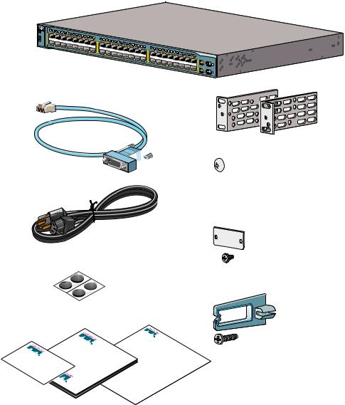
Shipping Box Contents (All Catalyst 3560 Switches Except the Catalyst 3560-8PC Switch)
SYST |
RPS
STAT
DUPLX
SPEED
PoE
MODE
1X
2X
1 |
2 |
3 |
4 |
|
|
|
|
|
|
|
|
|
|
|
|
|
|
|
|
5 |
6 |
7 |
8 |
|
|
|
|
|
|
|
|
|
|
|
|
|
|
|
|
9 |
10 |
11 |
12 |
|
|
|
|
|
|
|
|
|
|
|
|
|
|
|
|
13 |
14 |
15 |
16 |
17 |
18 |
19 |
20 |
|
|
|
|
|
|
|
|
|
|
|
|
|
|
|
|
|
|
|
|
|
|
|
|
|
|
|
15X 17X |
|
21 |
22 |
|
|
|
|
|
|
|
|
|
|
|
|
|
|
|
|
|
|
|
|
|
|
|
|
|
||
|
|
|
|
|
|
23 |
24 |
25 |
26 |
|
|
|
|
|
|
|
|
|
|
|
|
|
|
|
|
|
|
|
|
|
|
|
|
|
|
|
|
|
|
|
27 |
28 |
29 |
30 |
|
|
|
|
|
|
|
|
|
|
|
|
|
|
|
|
|
|
|
|
|
|
|
|
|
|
|
|
|
|
|
31 |
32 |
|
|
|
|
|
|
|
|
|
|
|
|
|
|
|
|
|
|
|
|
|
|
|
|
|
|
|
|
|
|
33 |
34 |
35 |
36 |
|
|
|
|
|
|
|
|
|
|
|
|
|
|
|
|
|
|
|
|
|
|
|
|
|
|
|
31X 33X |
|
|
|
37 |
38 |
39 |
40 |
|
|
|
|
|
|
|
|
16X 18X |
|
|
|
|
|
|
|
|
|
|
|
|
|
|
|
|
|
|
|
|
|
|
41 |
42 |
43 |
44 |
|
|
|
|
|
|
|
|
|
|
|
|
|
|
|
|
|
|
|
|
|
|
|
|
|
|
|
|
|
|
|
45 |
46 |
47 |
48 |
|
|
|
|
|
|
|
|
|
|
|
|
|
|
|
32X34X |
|
|
|
|
|
|
|
|
|
|
|
|
|
|
|
Catalyst 3560 switch
|
Catalyst 3560G |
SERIES PoE-48 |
|
|
|
47X |
|
|
|
49 |
51 |
|
|
|
48X |
50 |
52 |
|
|
Two 19-inch mounting brackets


 Four number-12 Phillips machine screws


 Four number-8 Phillips truss-head screws Console cable


 Six number-8 Phillips flat-head screws
Connector cover for redundant
power system (RPS)
AC power cord
Two number-4 pan-head screws
Four rubber mounting feet
|
Catalyst |
|
|
|
Regulatory |
|
||||
|
Getting |
|
|
|
|
and |
Safety |
|
|
|
|
|
3560 |
|
Catalyst |
|
Compliance |
||||
Product |
|
Started |
|
Switch |
|
3560 |
|
|
||
Cisco |
|
|
|
|
|
|
|
Information |
||
|
|
|
|
|
|
the |
|
|||
Registration |
|
|
|
Guide |
|
|
Switch |
|||
Ownershipcard |
|
|
|
|
|
|
|
|||
Cable guide
One black Phillips machine screw
Documentation
3
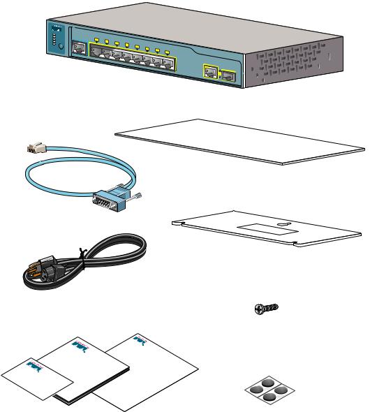
Shipping Box Contents (only the Catalyst 3560-8PC Switch)
SYST |
|
|
|
|
|
|
|
|
|
STAT |
CONSOLE |
1x |
|
|
|
|
|
|
|
DPLX |
2x |
|
|
|
|
|
|
||
SPD |
|
|
3x |
|
|
|
|
|
|
PoE |
|
|
|
4x |
5x |
|
|
|
|
|
|
|
|
|
|
|
|
||
|
|
|
|
|
|
6x |
|
|
|
MODE |
|
|
|
|
|
|
7x |
|
|
|
|
|
|
|
|
|
8x |
||
|
|
|
|
|
|
|
|
|
Catalyst 3560 switch
Catalyst |
|
|
3560 |
SERIES |
PoE-8 |
1 |
|
|
Mounting magnet
Console cable
Screw template
AC power cord (AC-powered switches only)
|
|
|
|
|
|
|
|
|
|
|
Three number-8 |
|
Catalyst |
|
|
|
Regulatory |
Phillips pan-head screws |
|||||
|
|
|
|
|
|||||||
|
Getting |
|
|
|
|
and |
Safety |
|
|
||
|
|
3560 |
|
Catalyst |
|
Compliance |
|||||
|
|
|
|
for |
|
|
|
||||
|
|
Started |
|
Switch |
|
3560 |
|
|
|||
|
|
|
|
|
|
|
|
|
Information |
||
ProductCisco |
|
|
|
Guide |
|
|
the |
|
|||
|
|
|
|
|
|
Switch |
|||||
Registration |
|
|
|
|
|
|
|
|
|
|
|
Ownershipcard |
|
|
|
|
|
|
|
|
|
|
|
|
Documentation |
|
|
|
|
|
Four rubber mounting feet |
||||
4
3 Running Express Setup
When you first set up the switch, you should use Express Setup to enter the initial IP information. This enables the switch to connect to local routers and the Internet. You can then access the switch through the IP address for further configuration.
To run Express Setup:
Step 1 Make sure that nothing is connected to the switch.
During Express Setup, the switch acts as a DHCP server. If your PC has a static IP address, change your PC settings before you begin to temporarily use DHCP.
Step 2 Power the switch by connecting the supplied AC power cord to the switch power connector and to a grounded AC outlet.
Step 3 When the switch powers on, it begins the power-on self-test (POST). During POST, the LEDs blink while tests verify that the switch functions properly.
Wait for the switch to complete POST, which can take several minutes.
Step 4 Verify that POST has completed by confirming that the SYST LED remains green. If the switch fails POST, the SYST LED turns amber.
POST errors are usually fatal. Contact your Cisco technical support representative if your switch fails POST.
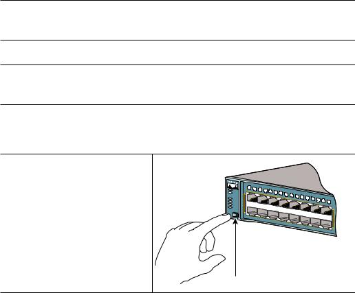
Step 5 Press and hold the Mode button for 3 seconds. When all of the LEDs left of the Mode button turn green, release the Mode button.
If the LEDs left of the Mode button begin to blink after you press the button, release it. Blinking LEDs mean that the switch has already been configured and cannot go into Express Setup mode. For more information, see the “Resetting the Switch” section on page 24.
|
SYST |
1 |
2 |
3 |
|
|
|
|
|
|
|
|
|
|
|
|
|
|
|
4 |
5 |
|
|
|
|
|
|
|
|
|
|
|
|||
|
1X |
|
|
6 |
|
|
|
|
|
|
|
|
|
|
|||
|
RPS |
|
|
|
|
7 |
8 |
|
|
|
|
|
|
|
|
||
|
|
|
|
|
|
|
9 |
10 |
|
|
|
|
|
|
|||
|
STAT |
|
|
|
|
|
|
|
|
|
11 |
12 |
13 |
14 |
|
|
|
|
|
|
|
|
|
|
|
|
|
|
|
|
15 |
16 |
|||
|
DUPLX |
|
|
|
|
|
|
|
|
|
|
|
|
|
|||
|
|
|
|
|
|
|
|
|
|
|
|
|
|
|
|
||
|
SPEED |
|
|
|
|
|
|
|
|
|
|
|
|
|
|
|
|
|
PoE |
|
|
|
|
|
|
|
|
|
|
|
|
|
|
|
15X |
MODE |
|
2X |
|
|
|
|
|
|
|
|
|
|
|
|
|
|
|
|
|
|
|
|
|
|
|
|
|
|
|
|
|
|
|
|
16X |
Mode button
Step 6 Verify that the switch is in Express Setup mode by confirming that all LEDs left of the Mode button are green. (On some models, the RPS and PoE LEDs remain off.)
5

Step 7 Connect a Category 5 Ethernet cable to any 10/100 or 10/100/1000 Ethernet port on the switch front panel.
Connect the other end of the cable to the Ethernet port on your PC.
Step 8 Verify that the LEDs on both Ethernet ports are green.
Wait 30 seconds.
Step 9 Start a web browser on your PC. Enter the IP address 10.0.0.1 in the web browser, and press Enter.
Catalyst |
PoE-48 |
3560G |
|
49 |
51 |
50 |
52 |
DHCP-enabled PC
The Express Setup page appears. If it does not appear, see the “In Case of Difficulty” section on page 23 for help.
6
Step 10 Enter this information in the Network Settings fields:
•In the Management Interface (VLAN ID) field, the default is 1. Enter a new VLAN ID only if you want to change the management interface through which you manage the switch. The VLAN ID range is 1 to 1001.
•In the IP Address field, enter the IP address of the switch. In the IP Subnet Mask field, click the drop-down arrow, and select an IP Subnet Mask.
•In the Default Gateway field, enter the IP address for the default gateway (router).
•Enter your password in the Switch Password field. The password can be from 1 to 25 alphanumeric characters, can start with a number, is case sensitive, allows embedded spaces, but does not allow spaces at the beginning or end. In the Confirm Switch Password field, enter your password again.
Step 11 (Optional) You can enter the Optional Settings information now or enter it later by using the device manager interface:
•In the Host Name field, enter a name for the switch. The host name is limited to 31 characters. Embedded spaces are not allowed.
•Enter the date, time, and time zone information in the System Date, System Time, and Time Zone fields. Click Enable to enable daylight saving time.
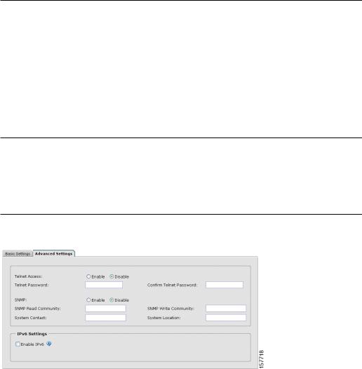
Step 12 (Optional) Click the Advanced Settings tab on the Express Setup window, and enter the advanced settings now or enter them later by using the device manager interface.
7
Step 13 (Optional) Enter this information in the Advanced Setting fields:
•In the Telnet Access field, click Enable if you are going to use Telnet to manage the switch by using the command-line interface (CLI). If you enable Telnet access, you must enter a Telnet password.
•In the Telnet Password field, enter a password. The Telnet password can be from 1 to 25 alphanumeric characters, is case sensitive, allows embedded spaces, but does not allow spaces at the beginning or end. In the Confirm Telnet Password field, re-enter the Telnet password.
•In the SNMP field, click Enable to enable Simple Network Management Protocol (SNMP). Enable SNMP only if you plan to manage switches by using CiscoWorks 2000 or another SNMP-based network-management system.
•If you enable SNMP, you must enter a community string in the SNMP Read Community field, the SNMP Write Community field, or both. SNMP community strings authenticate access to MIB objects. Embedded spaces are not allowed in SNMP community strings. When you set the SNMP read community, you can access SNMP information, but you cannot modify it. When you set the SNMP write community, you can both access and modify SNMP information.
•In the System Contact and System Location fields, enter a contact name and the wiring closet, floor, or building where the switch is located.
Step 14 (Optional) You can enable Internet Protocol version 6 (IPv6) on the switch. From the Advanced Settings tab, check the Enable IPv6 check box.
Note Enabling IPv6 restarts the switch when you complete Express Setup.
Step 15 To complete Express Setup, click Submit from the Basic Settings or the Advanced Settings tab to save your settings, or click Cancel to clear your settings.
When you click Submit, the switch is configured and exits Express Setup mode. The PC displays a warning message and tries to connect with the new switch IP address. If you configured the switch with an IP address that is in a different subnet from the PC, connectivity between the PC and the switch is lost.
Step 16 Disconnect the switch from the PC, and install the switch in your production network. See the “Managing the Switch” section on page 9 for information about configuring and managing the switch.
If you need to rerun Express Setup, see the “Resetting the Switch” section on page 24.
8
Refreshing the PC IP Address
After you complete Express Setup, you should refresh the PC IP address.
For a dynamically assigned IP address, disconnect the PC from the switch, and reconnect it to the network. The network DHCP server assigns a new IP address to the PC.
For a statically assigned IP address, change it to the previously configured IP address.
4 Managing the Switch
After completing Express Setup and installing the switch in your network, use the device manager or other management options described in this section for further configuration.
Using the Device Manager
You can manage the switch by using the device manager that is in the switch memory. This is a web interface that offers quick configuration and monitoring. You can access the device manager from anywhere in your network through a web browser.
Follow these steps:
1.Start a web browser on your PC or workstation.
2.Enter the switch IP address in the web browser, and press Enter. The device manager page appears.
3.Use the device manager to perform basic switch configuration and monitoring. Refer to the device manager online help for more information.
4.For more advanced configuration, install Cisco Network Assistant as described in the next section.
Downloading Cisco Network Assistant
Cisco Network Assistant is a free software program that you download from Cisco.com and run on your PC. Network Assistant offers advanced options for configuring and monitoring multiple devices, including switches, switch clusters, switch stacks, routers, and access points. Network Assistant is free—there is no charge to download, install, or use it.
Follow these steps:
1.Go to this Web address: http://www.cisco.com/go/NetworkAssistant
You must be a registered Cisco.com user, but you need no other access privileges.
2.Find the Network Assistant installer.
9
3.Download the Network Assistant installer, and run it. (You can run it directly from the Web if your browser offers this choice.)
4.When you run the installer, follow the displayed instructions. In the final panel, click Finish to complete the Network Assistant installation.
Refer to the Network Assistant online help and the getting started guide for more information.
Command-Line Interface
You can enter Cisco IOS commands and parameters through the CLI. Access the CLI either by connecting your PC directly to the switch console port or through a Telnet session from a remote PC or workstation.
Follow these steps:
1.Connect the supplied RJ-45-to DB-9 adapter cable to the standard 9-pin serial port on the PC. Connect the other end of the cable to the console port on the switch.
2.Start a terminal-emulation program on the PC.
3.Configure the PC terminal emulation software for 9600 baud, 8 data bits, no parity, 1 stop bit, and no flow control.
4.Use the CLI to enter commands to configure the switch. See the software configuration guide and the command reference for more information.
Other Management Options
You can use SNMP management applications such as CiscoWorks Small Network Management Solution (SNMS) and HP OpenView to configure and manage the switch. You also can manage it from an SNMP-compatible workstation that is running platforms such as HP OpenView or SunNet Manager.
The Cisco IE2100 Series Configuration Registrar is a network management device that works with embedded CNS agents in the switch software. You can use IE2100 to automate initial configurations and configuration updates on the switch.
See the “Accessing Help Online” section on page 24 for a list of supporting documentation.
10
5 Installing the Switch
Depending on the switch model, you can install the switch in a rack, on a wall, on or under a desk or shelf, and with a magnet or rack-mount brackets. This section covers rack-, desk-, shelf-, and magnet-mounting a switch. Depending on the switch, For alternate mounting procedures, see the
Catalyst 3560 Switch Hardware Installation Guide on Cisco.com.
Equipment That You Supply
You need this equipment to install the switch:
•Number-2 Phillips screwdriver
•Drill with a #27 drill bit (0.144-inch [3.7 mm])
Note A drill is required if you are securing the Catalyst 3560-8PC switch to a desk or a wall.
Before You Begin
When determining where to install the switch, verify that these guidelines are met:
•Airflow around the switch and through the vents is unrestricted.
Note We strongly recommend that you allow at least 3 inches (7.6 cm) of clearance around the ventilation openings.
•Temperature around the switch does not exceed 113˚F (45˚C).
•Humidity around the switch does not exceed 85 percent.
•Altitude at the installation site is not greater than 10,000 feet.
•Do not place any items on the top of the Catalyst 3560-8PC switch.
•The heatsinks and the bottom of the Catalyst 3560-8PC switch might be hot to the touch if the switch is operating at its maximum temperature 113˚F (45˚C) and is in an environment that exceeds normal room temperature (such as in a closet, in a cabinet, or in a closed or multirack assembly).
•Allow at least 1.75 inches (4 cm) of clearance above each Catalyst 3560-8PC switch in the rack.
11
Loading...