


TM
TM
Illustrated Instruction Manual for ML500 Garage Door Operator
|
|
|
|
ROLLING |
CODE |
|
|
|
|
|
|
|
|
|
|
L |
|
|
|
|
M |
|
|
|
|
E |
|
|
|
|
|
35 |
|
|
|
|
|
3 |
|
|
|
|
|
4 |
|
|
|
|
|
l8 |
|
|
|
|
|
e |
|
|
|
|
d |
|
|
|
|
o |
|
|
|
|
|
M |
|
|
|
|
|
Chamberlain Australia Pty Ltd
PO Box 1446
Lane Cove NSW 1595
www.motorlift.com.au
Chamberlain New Zealand Ltd
P.O. Box 100-221
Auckland 1330
www.motorlift.co.nz
2
These safety alert symbols mean WARNING – a personal safety or property damage instruction. Read these instructions carefully.
This garage door opener is designed and tested to offer reasonable safe service provided it is installed and operated in strict accordance with the following safety rules.
Failure to comply with the following instructions may result in serious personal injury or property damage.
WARNING: If your garage has no service entrance door, Model 1702AML Outside Quick Release must be installed. This accessory allows manual operation of the garage door from outside in case of power failure.
|
|
|
|
|
|
|
|
|
|
|
|
|
|
|
|
|
|
|
|
|
|
|
|
|
|
|
|
|
Keep garage door balanced.Sticking or bind- |
||||||
|
|
|
|
|
|
|
|
Fasten the child warning label adjacent to the |
|||
|
|
|
|
|
|
|
|
|
|||
|
|
|
|
|
ing doors must be repaired. Garage doors, door |
|
|
|
lighted door control button as a reminder of safe |
|
|
|
|
|
|
|
springs, cables, pulleys, brackets and their |
|
|
|
operating procedures. |
|
|
|
|
|
|
|
hardware are under extreme tension and can |
|
|
|
Disengage all existing garage door locks to |
|
|
|
|
|
|
|
|
|
|
|
|||
|
|
|
|
|
cause serious personal injury. Do not attempt |
|
|
|
|
||
|
|
|
|
|
to loosen, move or adjust them. Call for |
|
|
|
avoid damage to garage door. |
|
|
|
|
|
|
|
garage door service. |
|
|
|
|
Any door control buttons (if installed) MUST be |
|
|
|
|
|
|
|
|
|
|
|
||
|
|
|
|
|
Do not wear rings, watches or loose cloth- |
|
|
|
located where the garage door is visible, but |
|
|
|
|
|
|
|
|
|
|
|
|||
|
|
|
|
|
|
|
|
|
|||
|
|
|
|
|
ing while installing or servicing a garage door |
|
|
|
out of the reach of children. Do not allow |
|
|
|
|
|
|
|
opener. |
|
|
|
|
children to operate push button(s) or remote |
|
|
|
|
|
|
To avoid serious personal injury from en angle- |
|
|
|
control(s). Serious personal injury from a |
|
|
|
|
|
|
|
|
|
|
|
|||
|
|
|
|
|
|
|
|
closing garage door may result from misuse |
|
||
|
|
|
|
|
|
|
|
|
|||
|
|
|
|
|
ment, remove all ropes connected |
to the |
|
|
|
of the opener. |
|
|
|
|
|
|
garage door before installing the door opener. |
|
|
|
Activate opener ONLY when the door is in |
|
|
|
|
|
|
|
|
|
|
|
|||
|
|
|
|
|
Installation and wiring must be in compliance |
|
|
|
|
||
|
|
|
|
|
|
|
|
|
|||
|
|
|
|
|
|
|
|
full view, free of obstructions and opener is |
|
||
|
|
|
|||||||||
|
|
|
|
|
with your local building and electrical codes. |
|
|
|
properly adjusted. No one should enter or |
|
|
|
|
|
|
|
This is a class 2 double insulated product, |
|
|
|
leave the garage while the door is in motion. |
|
|
|
|
|
|
|
|
|
|
|
|||
|
|
|
|
|
connection to earth is not required or pro- |
|
|
|
Do not allow children to play near the door. |
|
|
|
|
|
|||||||||
|
|
|
|
|
vided. |
|
|
|
|
|
|
|
|
|
|
|
Lightweight doors of fiberglass, aluminum |
|
|
|
Use manual release only to disengage the trol- |
|
|
|
|
|
|
|
|
|
|
|
|||
|
|
|
|
|
|
|
|
|
|||
|
|
|
|
|
or steel must be substantially reinforced to |
|
|
|
ley and, if possible, ONLY when the door is |
|
|
|
|
|
|
|
avoid door damage. The best solution is to |
|
|
|
closed. Do not use the red handle to pull the |
|
|
|
|
|
|
|
check with your garage door manufacturer for |
|
|
|
door open or closed. |
|
|
|
|
|
|
|
|
|
|
|
|||
|
|
|
|
|
an opener installation reinforcement kit. |
|
|
|
|
Disconnect electric power to the garage |
|
|
|
|
|
|
|
|
|
|
|
||
|
|
|
|
|
The safety reverse system test is very |
|
|
|
|
||
|
|
|
|
|
|
|
|
door opener before making repairs or |
|
||
|
|
|
|
|
important.Your garage door MUST reverse on |
|
|
|
removing covers. |
|
|
|
|
|
|
|
contact with a 40mm obstacle placed on the |
|
|
|
|
||
|
|
|
|
|
floor. Failure to properly adjust the opener may |
|
|
|
This product is provided with a transformer and |
|
|
|
|
|
|
|
result in serious personal injury from |
closing |
|
|
|
|
|
|
|
|
|
|
garage door. Repeat the test once a |
month |
|
|
|
power supply cord of special design which, if |
|
|
|
|
|
|
and make any needed adjustments. |
|
|
|
|
damaged, MUST be replaced by a trans- |
|
|
|
|
|
|
|
|
|
|
|
former from your local Chamberlain distrib- |
|
|
|
|
|
|
|
|
|
|
|
|
|
|
|
|
|
|
This unit should not be installed in a damp |
|
|
|
utor and fitted by a specialist. |
|
|
|
|
|
|
|
or wet space. |
|
|
|
|
SAVE THESE INSTRUCTIONS |
|
|
|
|
|
|
|
|
|
|
|
||
|
|
|
|
|
Door must not extend over a public byway |
|
|
|
|
|
|
|
|
|
|
|
|
|
|
|
|
||
|
|
|
|
|
during operation. |
|
|
|
|
|
|
|
|
|
|
|
|
|
|
|
|
|
|
|
|
|
|
|
|
|
|
|
|
|
|
|
|
|
|
|
|
|
|
|
|
|
|
|
|
Table of Contents |
Page |
llustration(s) |
|
|
|
|
|
|||||
|
|
|
|
|
Install The Protector System™ |
11 |
|
|
Safety Rules |
3 |
|
|
(Optional) |
20 |
|
||
|
|
Program Remote |
11 |
|
||||
Before You Begin |
3 |
1 |
|
Replace Light Bulb |
12 |
21 |
|
|
Door Types |
4 |
|
Operation Of Your Opener |
13 |
|
|
||
Tools Required |
4 |
2 |
|
Care Of Your Opener |
14 |
|
|
|
Hardware Provided |
4 |
3 |
|
Maintenance Of Your Opener |
14 |
|
|
|
Completed Installation |
5 |
4 |
|
Troubleshooting |
14 |
|
|
|
Assembly |
5-7 |
5 - 10 |
|
Wiring the Multi-Function Door |
|
|
|
|
Installation |
7-10 |
11 - 17 |
|
Control Panel and the Lighted |
12 |
22 |
|
|
Adjustment |
11 |
18 - 20 |
|
Door Control Button (Optional) |
|
|||
Test the Safety Reverse System |
11 |
19 |
|
Accessories |
12 |
23 |
|
|
I |
|
|
|
Replacement Parts |
13 |
24 |
|
|
|
|
|
|
|
Specifications |
14 |
|
|
3
Before You Begin |
|
|
|
|
|
|
1. L ok at the wall or ceiling above the garage door. The header bracket MUST be securely fastened to structural sup- |
||||||
ports. |
|
|
|
|
|
|
2. Do you have a finished ceiling in your garage? If so, a support bracket and additional fastening hardware (not sup- |
||||||
plied) may be required. |
|
|
|
|
|
|
3. Do you have an access door in addition to the garage door? If not, Model 1702AML Outside Quick Release |
|
|||||
Accessory is required. |
|
|
|
|
|
|
1 |
A |
|
3 |
|
2 |
|
|
|
|
1 |
|
|
|
|
|
|
3 |
|
|
|
|
B |
|
4 |
|
|
|
|
|
|
|
|
|
|
|
|
|
|
|
|
18 |
|
|
|
|
|
5 |
|
|
|
|
|
|
|
129 |
|
|
|
6 |
|
|
|
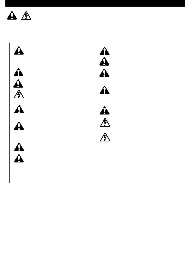
Door Types |
|
|
|
|
|
|
A. One-Piece Door with Horizontal Track Only |
|
|
|
|
|
|
B. Sectional Door with Curved Track |
|
|
|
|
16 |
|
NOTE: Unit will not work with One-Piece Doors with |
|
8 |
|
|
||
|
17 |
9 |
|
|||
Horizontal and Vertical Tracks, Double-Wing Doors, or |
|
|
|
|||
Canopy Doors. |
|
|
10 |
|
|
|
|
|
|
|
|
15 |
|
Tools Required for Installation |
|
|
|
|
||
|
7 |
|
|
|
||
|
|
|
|
|
|
|
|
|
|
12 |
|
|
|
|
|
|
|
11 |
|
|
|
|
|
|
|
13 |
|
2 |
12 |
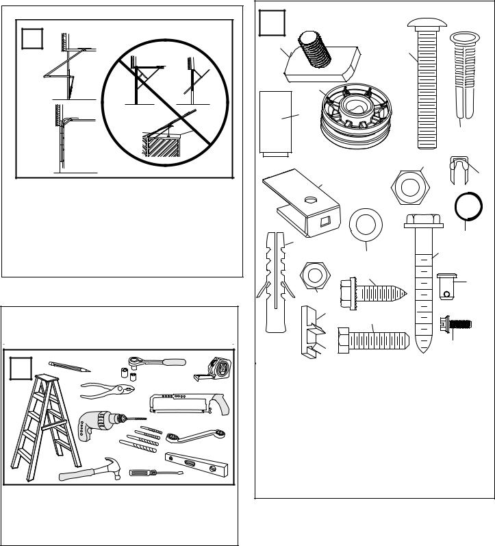
Hardware Provided |
|
|
||
|
|
ASSEMBLY HARDWARE |
|
|
|
|
|
|
|
(4x) |
(2) |
10. 6mm Self-Threading screw (4) |
|
|
|
|
1. Square Head Screw 6mm |
|||
|
|
|
2. 8mm Carriage Bolt |
(1) |
11. 6mm Hex Bolt |
(4) |
|
|
|
12. Wire Clips |
(3) |
||
|
|
|
3. Cable Pulley |
(1) |
||
|
|
|
13. Hex Screws |
(2) |
||
|
|
|
4. Pin |
(1) |
||
|
|
|
14. C-Rail Bracket (see image 9) |
|||
|
|
|
5. 8mm Lock Nut |
(1) |
||
|
|
|
15. Clevis Pin |
(2) |
||
|
|
|
6. Pulley Bracket |
(1) |
||
|
|
|
16. Ring Fastener |
(2) |
||
|
|
|
7. 6mm Nut |
(6) |
||
|
|
|
17. Flat Washer |
(1) |
||
|
|
|
8. Concrete Anchor |
(4) |
||
|
|
|
18 Anchor |
(2) |
||
|
|
|
9. 6mm Lag Bolt |
(4) |
||
|
|
. |
19. Insulated Staples |
(10) |
||
|
|
|
|
|||
|
|
|
|
|
|
|
4

4 |
Completed Installation |
|
|
|
|
|
|
|
|
||
|
As you proceed with the assembly, installation and |
||||
|
adjustment procedures in this manual, you |
|
find |
||
|
|
|
|
com- |
|
|
it helpful to refer back to this illustration of may |
|
|||
|
pleted installation. |
(8) Light Lens |
|
|
|
|
(1) |
Cable Pulley Bracket |
|
|
|
|
(2) Trolley |
(9) Manual Release |
|
||
|
(3) |
Chain/Cable Assembly |
Rope & Handle |
|
|
|
(4) |
Rail |
(10) Door Arm |
|
|
|
(5) |
Hanging Bracket |
(11) Door Bracket |
|
|
|
(6) |
Power Cord |
(12) Header Bracket |
|
|
|
(7) |
Opener |
|
|
|
|
|
|
4 |
6 |
|
1 |
2 |
3 |
5 |
|
|
|
|
|
|
|
|
12 |
|
|
|
7 |
|
|
|
|
|
|
|
11 |
10 |
|
|
8 |
|
|
|
|
|
||
|
|
9 |
|
9 |
NOTICE |
|
|
|
|
|
5 |
3
1
1
4
1
3 


 2
2
2
5 


 5
5
5  4
4
6
4
1
4
4
Assemble Rail
Place Rail pieces (1) on a flat surface for assembly. Take special note of the raised line on the Rail pieces (4) these lines MUST line up in order for the Rail to fit together properly. All three Rail sections are interchangeable. Slide Rail Braces (2) into slots on the sides of Rail. Make sure small tabs on Rail Braces (3) are up against top lip of Rail. Connect Rail by sliding other end of braces into next Rail. Be sure the raised lines that run down Rail sections
(4) line up. Tap Rail assembly (5) on a piece of wood (6) until Rail sections are flush. Repeat for final Rail section.
5
 Loading...