


|
® |
Installation and Operating Instructions |
|
Rolling Garage Door Opener |
|
|
LM650EVGB |
|
LM650EVGBSA |
|
LM850EVGBSA |
|
LM950EVGBSA |
|
Engineered and designed by The Chamberlain Group, Inc, USA |
Chamberlain GmbH |
Keep these instructions |
Alfred-Nobel-Strasse 4 |
for future reference |
66793 Saarwellingen |
|
Germany |
|
www.liftmaster.eu |
|

IMPORTANT |
Chain reduction assemblies that may interfere with the
safe and proper operation of the LM950EV must be removed.
All Hand chains must be removed prior to fitting the LM950EV.
DO NOT use extension poles with the LM950EV.
The LM950EV can be used on windlocked doors based on the following conditions:
-door is professionally installed, correctly sprung and maintained to manufacturer’s instruction
-door size up to 18m²
-product is only operated in normal conditions, not during adverse wind conditions

Start by Reading These Important Safety Instructions
WARNING: Failure to comply with the following instructions may result in serious personal injury or property damage.
• Read these instructions carefully and follow ALL instructions carefully
• The garage door opener is designed and tested to offer reasonable safe service provided it is installed and
operated in strict accordance with the instructions in this manual.
These safety alert symbols mean WARNING – a personal safety or property damage instruction. Read these instructions carefully.
Warning: If your garage has no service entrance door, a 1702EV outside quick release must be installed. This accessory allows manual operation of the garage door from outside in case of power failure.
Keep garage door balanced. Do not let the garage door opener compensate for a binding or sticking garage door. Sticking, binding or unbalanced doors must be repaired before installing this opener.
Do not wear rings, watches or loose clothing while installing or servicing a garage door opener. Wear gloves and suitable protective clothing where appropriate.
Frequently examine the door installation, in particular cable, springs and mountings for signs of wear, damage or imbalance. Do not use if repair or adjustment is needed since springs and hardware are under extreme tension and a fault
can cause serious personal injury.
To avoid serious personal injury from entanglement, remove all ropes, chains and locks connected to the garage door before installing the door opener.
Installation and wiring must be in compliance with your local building and electrical codes.
The safety reverse system test is very important. Your garage door MUST reverse on contact with a 50 mm obstacle placed on the floor. Failure to properly adjust the opener may result in serious personal injury from a closing garage door.
The door should not go back, if it reaches the door position „Closed“. If it still reverses both limits must be reprogrammed.
OPENING TEST: Apply 20 kg to the middle of the door. The door should not open completely.
Repeat the test once a month and make any necessary adjustments.
This appliance is not intended for use by persons (including children) with reduced physical, sensory or mental capablities, or lack of experience and knowledge, unless they have been given supervision or instruction concerning use of the
appliance by a person responsible for their safety.
Automatic Drive - Keep away from the area of the door as it may operate unexpectedly.
This opener should not be installed in a damp or wet space exposed to weather.
CONTENTS PAGE
SAFETY INSTRUCTIONS . . . . . . .1
CARTON INVENTORY . . . . . . . . . 2
TOOLS REQUIRED . . . . . . . . . . . .2
DOOR REQUIREMENTS . . . . . . . .2
PREPARE & TEST THE DOOR . .3-4
INSTALLATION . . . . . . . . . . . . . .5-6
CONNECT ELECTRIC POWER . . .6
ADJUSTMENT . . . . . . . . . . . . . . .7-8
INSTALL THE PROTECTOR
SYSTEM . . . . . . . . . . . . . . . . . . . . 9
WIRELESS PROGRAMMING ...10-11
The opener must not be used on a wicket door (door within a door).
The Protector SystemTMmust be used for all installations where the closing force as measured on the bottom of the door is over 400 N (40 kg). Excessive force will interfere with the proper operation of the safety reverse system or damage the garage door.
After installation, ensure that the parts of the door do not extend over public footpaths or roads.
Install the wireless wall control (or any additional wall control) in a location where the garage door is visible away from moving parts, at a height of at least 1.5 m and out of the reach of children. Do not allow children to operate push button(s) or transmitter(s). Serious personal injury from a closing garage door may result from misuse of the opener.
Permanently fasten the Warning Labels in prominent places, adjacent to wall controls and manual release mechanisms as a reminder of safe operating procedures.
Activate opener only when the door is in full view, free of obstructions and the opener is properly adjusted. No one should enter or leave the garage while the door is in motion.
Do not allow children to play near the door, or with door controls.
If the supply cord is damaged, it must be replaced by the manufacturer, its service agent or similarly qualified persons in order to avoid hazard.
Disconnect electric power and battery to the garage door opener before making repairs or removing covers.
KEEP THESE INSTRUCTIONS
BATTERY BACK UP UNIT . . . .12-13
MAINTAINING YOUR OPENER . . 14
CARE OF YOUR OPENER . . . . . 14
OPERATION OF YOUR OPENER 14
SPECIFICATION . . . . . . . . . . . . . .15
ACCESSORIES . . . . . . . . . . . . . . 15
WIRING & SPECIAL FEATURES . 16
DIAGNOSTIC CHART . . . . . . ..17-18
TROUBLESHOOTING . . . . . . . . ...19
WARRANTY . . . . . . . . . . . . . . . .20
1

1CARTON INVENTORY
1.Instruction manual (this document)
2.Stop collar
3.Clamp bracket
4.Release handle, cord and risk of entrapment card
5.Transmitters (2)
6.Wireless wall button (LM650EVGB only)
7.Hardware bag
8.Clamp plate
9.Warning label and risk of entrapment label
10.Opener
11.Extension poles (2) (LM650EVGB only)
11
2TOOLS REQUIRED
1.Ladder
2.Adjustable wrench for U-bolts already installed on the door
3.8 mm socket, 10 mm socket and 13 mm extended socket and socket wrench
4.300 mm socket extension (for minimum side-room installations)
5.Drill and 5.5 mm drill bit
6.Philips-head screwdriver
7.Marker pen
8.Door stand or similar device to safely support door (not shown)
13 mm, 10 mm, 8 mm
5.5 mm
3 DOOR REQUIREMENTS
The maximum allowable door height is 4.5 m with a maximum curtain area of 16.5 m²* (LM650EV) & 18 m²* (LM850EV) (door height in metres multiplied by the width in metres). The door must be spring balanced. *The Protector System™ (IR Beams) must be installed if the force at the edge of the closing door exceeds 400 N (40 kg). For LM950EV the maximum allowable door height is 5.5m (light commercial door) with a maximum curtain area of 25m² (door height in metres multiplied by the width in metres). The door must be of continuous corrugated sheet construction, spring balanced & of a mass not exceeding 250kg. Door axle diameter must not exceed 35mm.
Minimum distance from edge of curtain to edge of door bracket 45 mm
Direct clamping method
95 mm
95 mm
Independent clamping method
Ensure that there is at least 45 mm from the edge of the curtain to the edge of the bracket. If the roller door drum is on the edge of the curtain or is a smaller diameter, additional clearance may be required. If the drum is more than 60 mm from the curtain edge or of a smaller diameter, an extension pole kit may be required (section 10).
Different drum and bracket types may result in the minimum side room clearance not being possible and extension poles being required. Ensure there is a power point near the opener.
2
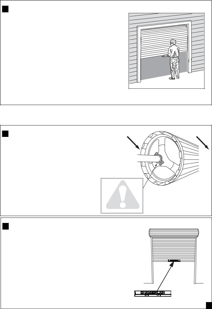
4 TESTING THE DOOR
Complete the following test to ensure your door is well balanced, and not sticking or binding:
•Disable all locks and remove any ropes connected to the garage door.
•Lift the door to about halfway and then release it. The door should remain spring balanced.
•Raise and lower the door to determine if there are any sticking or binding points (20 kg is the absolute maximum allowable to raise or lower the door in any position).
•If your door does not hold in place or the door binds or sticks, call a qualified door technician before installing the opener.
5 INSTALLING THE STOP COLLAR
Non opener side |
Opener side |
•Install the stop collar on the opposite end to where the opener is to be installed.
• Fit the stop collar hard against the boss of the door drum. Ensure the U-bolt holding the door shaft to the door bracket is tightly secured.
S AF E TY C HE C K !
Is the stop collar installed?
YES: proceed to the next step
NO: install the stop collar before proceeding
6 INSTALLING THE WEIGHT BAR (optional)
• Place the weight in the centre of the door (as shown).
• Use a pencil to mark the two hole positions.
• If the door curtain does not have a handle you will need to drill two 5.5 mm holes through the two marked positions, then place the weight bar on the inside of the door.
•Use the bolts, washers and nuts (provided) to fasten the weight bar in place.
NOTE: If the door has a lifting handle, remove the handle, |
|
nuts & bolts. Place weight bar over the handle holes, |
|
insert extended bolts through the weight bar & fasten handle back in place. |
3 |

7THE RELEASE HANDLE & CORD
•Thread one end of the rope through the hole in the top of the red release handle so that “NOTICE” reads right side up as shown.
•Secure with an overhand knot at least 25 mm from the end of the rope to prevent slipping.
Learn Limits
• Thread the other end of the rope through the loop of the manual button release cable.
DOWN Arrow |
||
• Adjust rope length so the handle (when installed) will be no higher button |
Release cable |
|
than 1.8 m above the floor. Secure with an overhand knot. If the |
|
|
door is greater than 2.5 m in height the release cord extension kit |
Rope |
|
accessory is required. |
||
|
||
|
Manual release |
|
NOTE: Final adjustment of handle height should be completed after |
warning label |
|
|
||
the opener is installed. If it is necessary to cut the rope, heat seal |
|
|
the cut end to prevent unravelling (refer section 16). |
|
|
|
Release handle |
|
UP Arrow button
Learn button
Overhand knot
8 OPERATING THE MANUAL RELEASE
To disengage the opener
Pull the release cord down firmly, (opener will make a clicking noise).
To re-engage the opener
Pull the release cord down firmly, (opener will make a clicking noise).
click
Pull down FIRMLY
Disablealllocksandandremoveremoveanyanyropesropesconnectedconnectedto theto garagaragethe door.door.
Take carewhenoperatingthethemanualmanualreleaserelease asn anopenopendoordoormaymayfall frallpidlyrapidlydue todueweakto weakor brokenor broken springs, or being out of balance.
9 PINNING THE DOOR
Note: A ballooning door may delay the safety reversal response and can compromise garage door security.
•To remedy any ballooning place self tapping metal screws or rivets where the curtain leaves the roll. Secure these
through the curtain into the drum wheel at each end of the roll.
•After determining the correct fastener location as shown, lift the door approximately half a turn from the closed position to allow access for drilling.
Free curtain |
Ballooning |
Add fasteners here |
|
|
|
|
|
|
Door closed |
Door can be Door secure |
|
lifted |
4

Extension pole
10ATTACHING EXTENSION POLES (IF REQUIRED)
(LM650EV / LM850EV ONLY)
Optional accessory for model LM850EV
• Align the extension pole holes with the drive legs.
Drive Leg
Reinforcing Brace
•Insert the extension poles into the drive leg and fix in place using screws provided.
•Slide the reinforcing brace over the poles and fix in place using the screws provided.
Reinforcing brace must be used.
Use extension pole kit part number 001B6449-1
Release cable |
|
Rope |
|
Manual Release |
Overhand knot |
Warning Label |
|
Release handle |
|
11 LEFT / RIGHT HAND INSTALLATION
LEFT
(handing must be changed during limit setting, section 13)
RIGHT (factory default setting)
|
|
|
|
|
|
|
|
|
|
|
|
|
|
|
|
|
|
|
|
|
|
|
|
|
|
|
|
|
|
|
|
|
|
|
|
|
|
|
|
|
|
|
|
|
|
|
|
|
|
|
|
|
|
|
|
|
|
|
Inside garage looking out |
|
|
|
5 |
||||||||||||
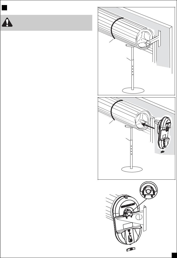
12 INSTALLATION PROCEDURE)
Do not allow people to walk under or around the door during the installation process as serious injury can occur.
NOTE: The opener can be installed on either side of the door. The following instructions are for RIGHT HAND INSTALLATIONS (as illustrated i.e. inside the garage looking out). For left hand installations, reverse the instruction terminology (eg LEFT for RIGHT etc).
Preparation:
•Place the opener in manual release mode (refer section 8).
•Open the roller door fully. For safety, tie a rope around the door.
•Ensure the door axle U-BOLT and door mounting bracket
on the left hand side (non opener side) are securely fastened.
•Support the door with a door stand or similar device to safely support the door.
•Mark the position of the door shaft on the right hand door bracket (for reassembly purposes).
•While the door is supported, remove the right hand axle U-Bolt and door mounting bracket from the wall.
Install the opener:
•Slide the opener over the door axle and engage the drive legs into the door drum wheel, either side of a spoke. Extensions may be necessary (refer section 10).
•Refit the door mounting bracket to the wall. If the door bracket needs to be relocated due to opener width, refer section 3.
•Clamp the opener on the door axle and door bracket in the marked position using the clamp assembly supplied (tighten to 25 – 28 Nm).
•If side room exceeds 95mm clamp independently to the door axle as illustrated in section 3.
•Remove all ropes and the support stand.
•Check the operation of the door in manual mode by raising and lowering by hand. It should operate smoothly without sticking or binding. The disengage handle should already be attached less than 1.8m
above the floor (refer section 7).
Connect the power:
•Position the power cable away from the door curtain and any moving parts.
•Plug the opener into a nearby power point and turn ON.
•The opener courtesy LEDs should turn ON.
•The opener must now be programmed for:-
•DOOR TRAVEL LIMITS (Section 13)
•RIGHT OR LEFT HAND OPERATION (Section 13)
•FORCE SETTING (Section 14)
Tighten to 25-28 Nm
6
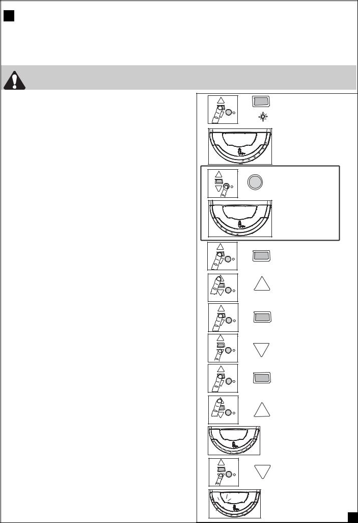
13 SETTING THE LIMITS FOR RIGHT OR LEFT HAND OPERATION AND FORCE
Travel limits set how far your door goes up and down. Your opener must be configured correctly for right or left hand installation to operate correctly, if not the door will rotate in the reverse direction.
NOTE: Opener is factory configured for right hand installation.
The opener will operate during this procedure. Make sure the door is clear of obstruction. Ensure your hands are away from any moving parts before activating the door.
Setting right or left hand operation:
•Ensure the door is positioned halfway and the opener is engaged.
•Turn the power ON. After 2 seconds the Courtesy LEDs will turn on.
•Press and hold the black (Limit) button until the orange indicator LED starts flashing, and then release. Either right or left courtesy LEDs will light up.
•For right hand installations, the right side bank of LEDs must light up, and for left hand installations, the left hand bank must light up.
•If the incorrect bank of LEDs is illuminated, simply press the Yellow learn button until the opposite bank lights up.
•Press and release the Black limit set button to accept hand. UP button will flash.
Setting the open (UP) limit:
•Press and hold the “UP” button, until the door reaches the desired open position, and then release. You can adjust the door by using the DOWN button and UP button to adjust as necessary. Make sure there is enough room for your vehicle to pass under.
•Press and release the Black limit set button to acknowledge the Up position.
•Courtesy light flashes twice and DOWN button will flash.
Setting the bottom (DOWN) limit:
•Press and hold the “DOWN” button until the door reaches the desired closed position. If the door closes too hard against the floor, use the UP and DOWN button to adjust.
•Press and release the Black limit set button to acknowledge the down position.
•Courtesy light flashes twice and UP button will flash.
Setting the FORCE:
•Press and release the UP button. The door will travel to the UP limit and the DOWN button will flash.
•Press and release the DOWN button. The door will travel to the DOWN limit.
•The indicator LED will stop flashing indicating the force has been learned.
NOTE: The courtesy LEDs will go out after 2.5 min.
•The door must travel through a complete cycle, UP and DOWN, in order for the force to be set properly.
If the opener cannot open and close your door fully, inspect your door to ensure that it is balanced properly and is not sticking or binding.
Press and hold until
FLASHING
LED
Right bank will light up
|
(IF REQUIRED) |
|
|
To change |
|
|
press and hold |
|
|
until correct |
|
|
bank lights up |
|
|
Left bank |
|
|
will light up |
|
|
for Left hand |
|
|
installation |
|
|
Press & release to accept |
|
|
selected hand. |
|
|
Press and hold to drive |
|
|
door up to open |
|
|
If required: Use DOWN button to adjust |
|
|
Press & release to set the |
|
|
UP limit |
|
|
Press and hold to drive |
|
|
door down to closed |
|
|
If required: Use UP button to adjust |
|
|
Press & release to set the |
|
|
DOWN limit |
|
|
Activate door to open |
|
|
Orange |
|
|
LED ON & |
|
|
Courtesy LEDS |
|
|
on Dim |
|
|
Close the door to test limits |
|
Click |
Motor will make a click & |
|
FULL BRIGHT courtesy |
|
|
|
|
|
|
LEDs will turn on |
7 |
|
|
|
 Loading...