


•The Protector System™ - Safety Reversing Sensor Model 770E
For models LM60, LM600/800/1000A, 5580, 3780, BAS300, 3750E-1A, 4410E, PRO9000
•Das "Protektor System"-Sicherheitsreversionssensoren Modell 770E
Für Modelle LM60, LM600/800/1000A, 5580, 3780, BAS300, 3750E-1A, 4410E, PRO9000
•Système "Protector" - Détecteur Inversement de Sécurité Modèle 770E
Pour les modèles LM60, LM600/800/1000A, 5580, 3780, BAS300, 3750E-1A, 4410E, PRO9000
•Het Beveiligingssysteem - Beveiligingsdetector Model 770E
Voor modellen LM60, LM600/800/1000A, 5580, 3780, BAS300, 3750E-1A, 4410E, PRO9000
•Il sistema "Protector" - Sensore di sicurezza per l'inversione del moviemento Modello 770E
Per i modelli LM60, LM600/800/1000A, 5580, 3780, BAS300, 3750E-1A, 4410E, PRO9000
•Protector-systemet - Reverseringsavkännare modell 770E
För modeller LM60, LM600/800/1000A, 5580, 3780, BAS300, 3750E-1A, 4410E, PRO9000
•Beskyttersystemet - Sensor for sikkerhetsreversering Modell 770E
Modeller LM60, LM600/800/1000A, 5580, 3780, BAS300, 3750E-1A, 4410E, PRO9000
•Sikkerhedssystem - Sikkerhedsreversionssystem Model 770E
Modeller LM60, LM600/800/1000A, 5580, 3780, BAS300, 3750E-1A, 4410E, PRO9000
•Suojarjärjestelmä - Suojaperäytysjärjestelmä malli 770E
Mallien LM60, LM600/800/1000A, 5580, 3780, BAS300, 3750E-1A, 4410E, PRO9000
Review all safety warnings on Page one of your garage door operator owner’s manual.
Ensure that the door and all its operating gear is in good condition and works easily when it is manually operated.
HOT LINES: Germany 06838 / 907250 • France 03.87.98.62.84 • UK 01935 848526 • International 0049 6838 907 250
The Protector System™ - Safety Reversing Sensor Model 770E
Installation procedures are the same for sectional and one-piece doors.
To protect small children, install the Protector System™ no higher than 4"-6" (100mm-150mm) above the garage floor.
Disconnect power to the garage door opener before installing the
Protector System™.
Look at the label on the connector end of each case to identify the sensors.
The sending eye transmits an invisible light beam to the receiving eye.
If an obstruction breaks the light beam while the garage door is closing, the door will stop and reverse to full open position.
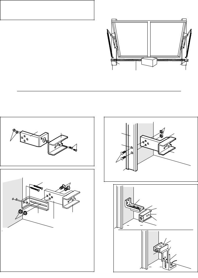
The units can be installed on either side of the garage door (Figure 1) as long as the sun never shines directly into the receiving eye lens, but the brackets must be connected and fastened so that the sending and receiving eyes face each other as shown in Figure 1.
The brackets must be securely fastened to a solid surface such as the studs on either side of the door, or add a piece of wood at each location if installing in masonry construction.
The invisible light beam path must be unobstructed. No part of the garage door (or door tracks, springs, hinges, rollers or other hardware) can interrupt the beam while the door is closing. If it does, use a piece of wood to build out each sensor mounting location to the minimum depth required for light beam clearance.
Sensor |
Sensor |
Unit |
Unit |
Left Side |
Invisible Light |
Right Side |
of Garage |
Beam Protection Area |
of Garage |
Figure 1: Facing the door from inside the garage
ASSEMBLY PROCEDURES
Figures 2, 3 and 4 show recommended assembly of bracket(s) and "C" wrap based on the wall installation of the sensors on each side of the garage door shown above, or on the garage door tracks themselves.
Figure 5 shows variations which may fit your installation requirements better. Make sure the wraps and brackets are aligned so the sensors will face each other across the garage door.
ALL Installations |
Figure 2 |
Mounting Bracket |
|
With Square Holes |
"C" Wrap |
|
|
|
#10-32x3/8" |
|
Screws |
#10-32 Lock Nuts
•Fasten the "C" wraps to the mounting brackets with square holes, using the hardware shown.
Garage WALL Installation |
Figure 3 |
1/4x1-1/2" |
1/4-20x1/2" Carriage Bolts |
Lag Screws |
(with square shoulder) |
Inside
Garage
W
|
Mounting Bracket |
"C" Wrap |
|
|
|
1/4"-20 |
with Slot |
Mounting Bracket |
|
|
Lock Nuts
with Square Holes
•Connect each assembly to a slotted bracket, using the hardware shown. Note alignment of brackets for left and right sides of the door. Finger tighten the lock nuts.
•Use bracket mounting holes as a template to locate and drill
(2) 3/16" (4,8mm) diameter pilot holes on both sides of the garage door, 4"-6" (100mm-150mm) above the floor (but not exceeding 6" (150mm).
•Attach bracket assemblies with 1/4"x1-1/2" lag screws as shown.
•Adjust right and left side bracket assemblies to the same distance out from mounting surface. Make sure all door hardware obstructions are cleared. Tighten the nuts securely.
|
Garage DOOR Track Installation |
Figure 4 |
|
|
|
1/4"-20 |
|
|
|
|
|
Garage |
Inside |
Lock Nuts |
|
|
Mounting Bracket |
||
Garage |
|
||
Door Track |
|
||
|
with Square Holes |
||
Wall |
|
||
|
|
||
|
|
|
|
Drill 3/8" |
|
|
|
(9,5mm) Holes |
|
|
|
|
|
|
"C" Shaped |
|
|
|
W |
1/4-20x1/2" Carriage Bolts
•Discard slotted bracket. Drill 3/8" (9,5mm) holes in each track and fasten securely with hardware as shown.
Inside |
|
Alternate Wall |
Figure 5 |
||
Mounting |
Mount |
|
|
||
Garage |
|
|
|
||
Bracket |
|
|
|
||
W |
|
|
|
|
|
|
with Slot |
|
|
|
|
|
|
Mounting |
|
|
|
|
|
|
|
|
|
|
|
|
Bracket with |
|
|
|
|
|
Square Holes |
|
|
|
|
|
"C" Wrap |
|
|
|
|
|
Sensor |
|
|
|
Garage |
Indicator Light |
|
||
|
|
|
|
||
|
Floor |
|
|
|
|
|
|
|
Inside |
|
Alternate Floor |
|
|
|
|
Mount |
|
|
|
|
Garage |
Indicator Light |
|
|
|
|
W |
|
Sensor |
|
|
|
|
|
Mounting Bracket |
|
|
|
|
|
with Square Holes |
|
|
|
|
|
Mounting Bracket |
|
|
|
|
|
with Slot |
|
|
|
"C" |
|
Attach with |
|
|
|
W |
|
|
|
|
|
|
concrete anchors |
|
|
|
|
|
|
|
|
|
|
Garage |
|
(not provided) |
|
|
|
|
|
|
|
|
|
Floor |
|
|
2-EN |
|
|
|
|
|
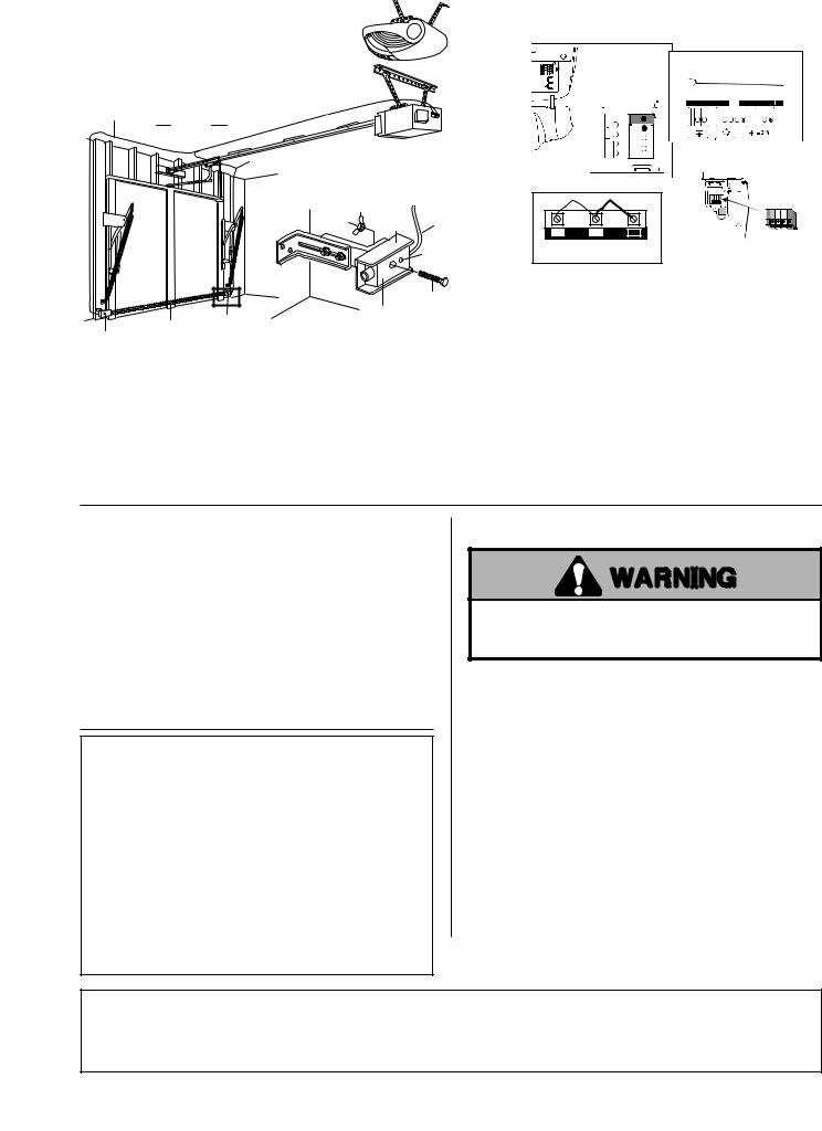
FIGURE 6 |
Connect Sensor Wires to |
|
Opener Terminals |
|
LM60 |
LM600A/LM800A/LM1000A
Connect Wire to
Opener Terminals
Bell Wire
Finished
Ceiling
Bell Wire
Wing Nut |
|
"C" Wrap |
Wire |
Indicator
Light

 3780/5580
1 |
2 |
3 |
4410E, 4210E, 3750E |
||
|
|
1/4-20x1-1/2" |
|
Sensor |
Hex Bolt |
Sensor |
Invisible Light Beam Sensor |
|
Protection Area |
|
•Center each sensor unit in a "C" wrap with lenses pointing toward each other across the door.
•Secure sensors with the hardware shown in Figure 6. Finger tighten the wing nut on the receiving eye to allow for final adjustment. Securely tighten the sending eye wing nut.
•Run wires from both sensors to the opener as shown in Figure 6. Use insulated staples to secure the wire to the wall and ceiling.
•Connect both sets of wires to the opener terminals as shown.
•Plug in the opener. If your opener has the Multi-Function Door
Control, make sure the Lock Feature is off. Red indicator lights in both the sending and receiving eyes will glow if wiring connections and alignment are correct.
If the indicator lights are blinking (and the invisible light beam path is not obstructed), alignment is required.
•Loosen the receiving eye wing nut to allow slight rotation of unit. Adjust sensor vertically and/or horizontally until the red indicator light glows.
•When indicator lights are glowing in both units, tighten the wing nut in the receiving eye unit.
TEST THE PROTECTOR SYSTEM™
•Press the remote control push button to open the door.
•Place an object large enough to obstruct the sensor beam in the path of the door.
•Press the remote control push button to close the door. The door will not move more than an inch (25mm).
The garage door opener will not close from a remote control if the indicator light in either sensor is blinking (alerting you to the fact that the sensor is misaligned or obstructed).
You can operate the garage door opener by disconnecting the safety reversing sensor.
Professional service is required if the opener closes the door when the Protector System™ is obstructed.
TROUBLE SHOOTING
1.If the sending eye or receiving eye indicator light does not glow after installation, check for:
•Electric power to the opener.
•A short in the black/white wires. These can occur under staples or at screw terminal connections.
•Incorrect wiring between sensors and opener.
•An open wire, (wire break).
•Lock switch on Multi-Function Door Control Panel is activated. Deactivate.
2.If both sensors are blinking, realign or remove obstruction.
3.If an infrared sensor has been installed, it can not be removed later on. The unit only operates with the IR sensor (starting September 2004).
4.If the IR sensors are damaged and cannot be repaired, the door, nevertheless, can be closed using the wall switch
TEST THE SAFETY REVERSE SYSTEM
Failure to test and adjust the safety reverse system may result in serious injury or death from a closing garage door. Repeat this test once a month and adjust as needed.
TEST:
•Place a one-inch (25mm) obstacle laid flat on the floor, centered under the garage door.
•Operate the door in the down direction. The door must reverse on striking the obstruction.
ADJUSTMENT:
If the door stops on the obstruction, it is not traveling far enough in the down direction.
•Increase the DOWN limit by turning the DOWN limit adjustment screw counterclockwise 1/4 turn.
•Repeat the test.
On a sectional door, make sure limit adjustments do not force the door arm beyond a straight up and down position.
•When the door reverses on the one-inch (25mm) obstacle, remove the obstruction and run the opener through 3 or 4 complete travel cycles to test adjustment.
If the door will not reverse after repeated adjustment attempts, call for professional door service.
REPLACEMENT PARTS
2-strand black & white wire with connector.................... |
41B4115 |
C-Wrap Bracket................................................................... |
12B483 |
Safety Sensor Kit (receiving and sending eyes only) ....... |
41A4373 |
Square Hole Bracket ........................................................... |
12B484 |
Safety sensor hardware bag ............................................ |
41A4116 |
Slotted Bracket.................................................................... |
12B485 |
3-EN
Das "Protektor System"-Sicherheitsreversionssensoren Modell 770E
Installationsmethode ist die gleiche für Sektionaltore und Kipptor.
Zur Identifizierung der Sensorenmodule, Etikettenaufschrift am Klemmenende jedes Moduls beachten.
Die Senderlinse sendet einen unsichtbaren Lichtstrahl zur Empfängerlinse.
Bei Unterbrechung des Lichtstrahls während des Schließvorganges hält das Tor an und öffnet es wieder vollständig.
Die Module können auf beiden Seiten des Garagentors installiert werden (Abb. 1) vorausgesetzt, daß das Sonnenlicht niemals in die Empfängerlinse scheint, die Konsolen müssen jedoch so befestigt und angeschlossen werden, daß Sendeund Empfangslinse einander gegenüberstehen, wie in Abb. 1 gezeigt.
Die Konsolen müssen sicher an einer festen Oberfläche, wie z.B. die Pfosten an beiden Seiten des Tors, befestigt sein; bei Installation auf dem Mauerwerk sollte an jeder Befestigungsstelle ein Stück Holz angebracht werden.
Der unsichtbare Lichtstrahl darf nicht unterbrochen werden. Kein Teil des Garagentores (z.B. Torschienen, Federn, Scharniere, Rollen, andere Kleinteile etc.) darf den Strahl während des Schließvorganges unterbrechen. In solch einem Falle sollte durch Unterlegung von Holz jede Sensorbefestigungsstelle soweit verschoben werden, daß eine dauerhafte Lichtstrahlausbreitung gewährleistet wird.
Zum Schutz von Kleinkindern sollte die Sicherheitslichtschranke nicht höher als 100mm-150mm über dem Garagenboden installiert werden.
Vor Montage der Sicherheitslichtschranke muß die Stromzufuhr zum Garagentorantrieb abgeschaltet werden.
|
|
|
|
|
|
|
|
|
|
|
|
|
|
|
|
|
|
|
|
|
|
|
|
|
|
|
|
|
|
|
|
|
|
|
|
|
|
|
|
|
|
|
|
|
|
|
|
|
|
|
|
|
|
|
|
|
|
|
|
|
|
|
|
|
|
|
|
|
|
|
|
|
|
|
|
|
|
|
|
|
|
|
|
|
|
|
|
|
|
|
|
Sensor- |
|
|
|
|
Sensor- |
|
|
|
||||
|
|
|
|
|
|
|
|
|
||||||
|
|
|
|
|
|
|
|
|
||||||
|
|
|
|
|
|
|
|
|
||||||
|
|
Unsichtbarer |
modul |
|
|
|||||||||
|
|
modul |
|
|
||||||||||
Linke |
Lichtstrahl |
|
|
Rechte |
||||||||||
|
|
|
|
|
||||||||||
Garagenseite |
Schutzbereich |
Garagenseite |
||||||||||||
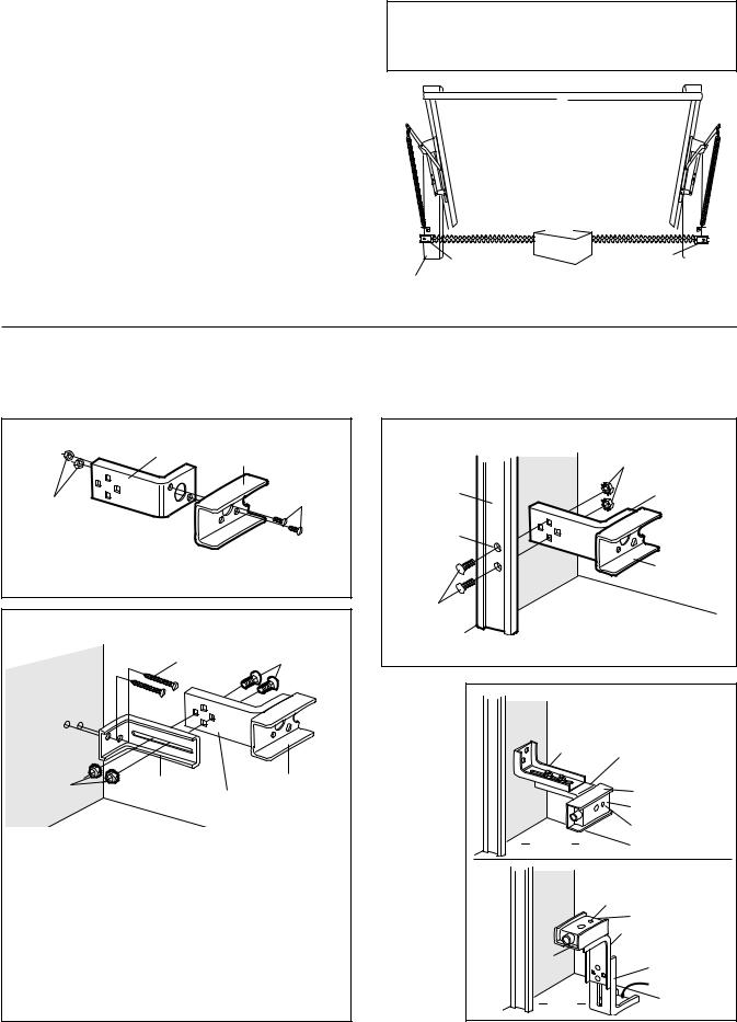
ABB. 1: Tor von der Innenseite der Garage
MONTAGE
Abbildungen 2, 3 und 4 zeigen die empfohlene Montage der Konsolen und des C-Profils an der Wand von jeder Garagentorseite oder an den Garagentorschienen.
Abb. 5 sind Montage-Varianten, die sich für Ihre Garage eventuell besser eignen. Vergewissern Sie sich, daß alle C-Profile und
Konsolen so ausgerichtet sind, daß die Sensoren einander gegenüberstehen.
Montage |
ABB. 2 |
Befestigungskonsole mit
vie
C-P
#10-32x3/8"
Schrauben
#10-32
Mutter mit Federring
•Das C-Profil an den Befestigungskonsolen (mit den viereckigen Löchern) unter Verwendung der gezeigten Schrauben befestigen.
Garagenwandmontage |
ABB. 3 |
1/4x1-1/2" |
1/4-20x1/2" |
Holzschrauben |
Schloßschrauben |
Garageninnenwand
1/4"-20 |
Befestigungskonsole |
C-P |
|
Mutter mit |
mit Schlitz |
Befestigungskonsole |
|
Federring |
|
mit viereckigen Löche |
|
•Konsole mit C-Profil unter Verwendung der gezeigten Schloßschrauben mit Muttern mit der geschlitzten Konsole verbinden. Konsole für linke und rechte Torseite ausrichten. Muttern mit Federring per Hand leicht anzeigen.
•Konsolenbefestigungslöcher als Anhaltspunkt für das Vorbohren der (2) 4,8mm Löcher an beiden Seiten des Garagentores benutzen, und zwar 100-150mm über Bodenhöhe (jedoch nicht höher als 150mm).
•Konsolen mit 1/4x1-1/2" Holzschrauben, wie gezeigt, anbringen.
•Rechte und linke Konsole im gleichen Abstand von der Befestigungsoberfläche ausrichten. Vergewissern Sie sich, daß der Lichtstrahl nicht unterbrochen wird, dann Schrauben oder Muttern fest anziehen.
|
Garagentorschienenmontage |
ABB. 4 |
|
|
|
|
|
|
|
1/4"-20 Mutter |
|
|
|
mit Federring |
|
Garagentor- |
Garagenin- |
|
Befestigungskonsole |
nenwand |
|
||
|
mit vierekigen Löchern |
||
schiene |
|
|
|
|
|
|
|
9,5mm |
|
|
|
Löcher |
|
|
|
boh |
|
|
|
BOHREN |
|
|
|
|
|
|
C-P |
1/4-20x1/2" Schloßschrauben
•Geschlitzte Konsole aussondern. In jeder Schiene 9,5mm Löcher bohren und mit Kleinteilen, wie gezeigt, sichern.
|
Wandbefestingungs- |
ABB. 5 |
|
Garagen- |
|
Variante |
|
|
|
|
|
innen- |
Befestingungs- |
|
|
wand |
konsole |
Befestigungs- |
|
|
mit Schlitz |
|
|
|
konsole mit |
|
|
|
|
|
|
|
|
vie |
|
|
|
Löchern |
|
|
|
C-Profil |
|
|
|
Sensor |
|
Garagen- |
Leuchtanzeige |
|
|
|
|
||
boden |
|
|
|
Garagen- |
Bodenbefestingungs- |
|
variante |
||
innen- |
Leuchtanzeige |
|
wand |
||
|
Sensor |
|
|
Befestigungkonsole mit |
|
|
vie |
rn |
C-P |
Befestigungskonsole |
|
|
mit Schlitz |
|
|
|
|
|
|
Mit Betonankern |
Garagen- |
|
befestigen |
|
(nicht mitgeliefert) |
|
boden |
|
|
|
|
|
4-DE

ABB. 6 |
Sensordrähte an |
|
Antriebsklemmanschlüße |
LM60
LM600A/LM800A/LM1000A
Draht an Öffner- 


 anschlüsse anschliessen


Klingeldraht Garagendecke
Klingeldraht
3780/5580
Unsichtbarer Sensor
Sensor Lichtstrahl Schutzbereich
Flügelmutter |
|
|
|
|
C-Profil |
Draht |
|
|
|
|
|
1 |
2 |
3 |
|
Leuchtanzeige |
4410E, 4210E, 3750E |
||
|
|
|
|
|
|
1/4-20x1-1/2" |
|
|
|
Sensor |
Sechskantschraube |
|
|
|
•Jeden Sensor im C-Profil zentrieren, so daß Linsen quer zum Tor aufeinander zeigen.
•Sensoren mit Schrauben, wie in Abb. 6 gezeigt, befestigen. Per Hand Flügelschraube an der Empfänger Linse leicht anziehen, damit eine spätere endgültige Ausrichtung möglich ist. Ziehen Sie die Flügelschraube der Sender-Linse fest an.
•Drähte der beiden Sensoren mit dem Garagentorantrieb, wie unter Abb. 6 gezeigt, verbinden. Die isolierten Klammern zur Befestigung der Drähte an Wand und Decke verwenden.
•Beide Drahtpaare, wie gezeigt, mit den Öffnerklemmen verbinden.
•Garagentorantrieb an das Stromnetz anschließen. Falls Ihr
Antrieb mit einem Doppelschalter ausgerüstet ist, vergewissern Sie sich, daß die Funksteuerung vorhanden ist. Beide Leuchtanzeigen, sowohl in der Sendeals auch in der Empfangslinse leuchten auf, wenn die Klemmanschlüsse und Ausrichtung korrekt sind.
Falls die Leuchtanzeigen blinken (und wenn der unsichtbare Lichtstrahl nicht blockiert ist) ist eine Ausrichtung erforderlich.
•Die Empfangslinsen-Flügelschraube lockern, sodaß leichte Drehungen möglich sind. Sensor vertikal und/oder horizontal justieren bis die rote Leuchtanzeige aufleuchtet.
•Wenn die Leuchtanzeige in beiden Modulen aufleuchtet, kann die Flügelschraube im Empfangslinsenteil fest angezogen werden.
ÜBERPRÜFUNG DER
SICHERHEITSLICHTSCHRANKE
•Drücken Sie die Fernbedienungstaste zum Öffnen des Tors.
•Ein genügend grosses Hindernis unter das Tor legen, damit der Sensorstrahl im Torweg unterbrochen wird.
•Drücken Sie die Fernbedienungstaste zum Schließen des Tores. Das Tor bewegt sich 25mm.
Der Garagentorantrieb schliesst nicht, wenn die Leuchtanzeige in einem der Sensoren blinkt (was bedeutet daß der Sensor nicht ausgerichtet ist oder, durch ein Hindernis blockiert wird).
Durch Lösen der Kabelverbindung des Sensors im Sicherheitsreversionssystem können Sie das Garagentor unter Betätigung des Garagentorantriebes öffnen.
Ein Fachmann sollte zu Rate gezogen werden, falls der Antrieb das Tor schliesst, obwohl es durch ein Hindernis blockiert wird.
FEHLERSUCHE
1.Falls die Sendeoder Empfangsanzeigeleuchte nach Installation nicht aufleuchtet, prüfen Sie folgendes:
•Stromversorgung zum Antrieb.
•Kurzschluss im schwarz/weißen Draht. Dies kann auftreten beim Krampen oder an Anschlußklemmen.
•Falscher Leitungsanschluss zwischen Sensor und Antrieb.
•Unterbrechung des Stromkreislaufs (unterbrochene Leitung).
•Die Funksteuerung am Doppelschalter ist abgeschaltet. Anstellen!
2.Falls beide Sensoren blinken, ausrichten oder Hindernis entfernen.
3.Wurde eine Lichtschranke angeschlossen, kann diese später nicht mehr entfernt werden. Der Antrieb funktioniert nur mehr mit der Lichtschranke (ab September 2004).
4.Wurde ein Defekt an der Lichtschranke festgestellt und kann dieser nicht behoben werden, kann das Tor mittels des Wandtasters (dauernd drücken) trotzdem geschlossen werden.
ÜBERPRÜFUNG DES
SICHERHEITSREVERSIONSYSTEMS
Nichtbefolgung der Überprüfung und Einstellung des Sicherheitsreversionsystems kann ernsthafte oder lebensgefährliche Verletzungen durch ein sich schliessendes Garagentor verursachen. Ein entsprechender Test sollte einmal monatlich wiederholt werden. Wenn notwendig, muß der Antriebe neu eingestellt werden.
ÜBERPRÜFUNG:
•25mm starkes Holzstück auf den Boden unter das Tor legen.
•Öffner betätigen. Tor MUSS bei Kontakt mit dem Holz zurücklaufen.
EINSTELLUNG:
•Wenn das Tor nur anhält, muß die Torhöheneinstellung um 90 Grad nach links gedreht werden.
•Test Wiederholen.
Bei Sektionaltoren vergewissern Sie sich, daß die Begrenzungseinstellung den Torarm nicht über die senkrechte Position hinausschiebt.
•Wenn das Tor nach Berührung des (25mm) Hindernis reversiert, entfernen Sie das Hindernis, und fahren drei bis bier Öffnungsund Schließvorgänge, um die genaue Einstellung des Antriebs zu testen.
Falls das Tor nach wiederholten Einstellversuchen nicht zurückläuft rufen Sie bitte Ihren Tor-Reparaturservice an.
ERSATZTEILE
2-Drahtlitzen schwarz und weiß mit Anschluss................. |
41B4115 |
C-Profil-Konsole .................................................................. |
12B483 |
Sicherheitssensor-Kit (Nur Empfangsund Sendeauge) .. |
41A4373 |
Viereckloch-Konsole............................................................ |
12B484 |
Sicherheitssensor-Tasche mit Kleinteilen.......................... |
41A4116 |
Schlitzkonsole...................................................................... |
12B485 |
5-DE

SYSTEME "PROTECTOR" - DETECTEUR A INVERSEMENT DE SECURITE MODELE 770E
LE PROCESSUS D’INSTALLATION EST LE MEME POUR LES PORTES PLEINES ET LES PORTES ARTICULEES.
Regardez l'étiquette placée près de la prise de branchement de chaque détecteur pour les identifier.
L'oeil émetteur transmet un rayon infra-rouge à l'oeil récepteur.
Si un obstacle interrompt le rayon lumineux pendant la fermeture de la porte s'arrêtera et repartira en sens inverse pour s'ouvrir complètement.
Les détecteurs peuvent être installès indifféremment de chaque coté de la porte du garage (Figure 1), à condition que le soleil n'éclaire jamais directement la lentille de l'oeil récepteur, mais les supports doivent être connectés et fixés de telle sorte que l'oeil récepteur et l'oeil émetteur soient placés l'un en face de l'autre tel qu'indiqué sur la figure 1.
Les supports doivent être fixés solidement sur une surface rigide et plane tel que les montants de la porte, ou une pièce de bois rajoutée à chaque endroit nécessaire s'il s'agit d'une construction en ciment.
Le trajet du rayon infra-rouge doit être dégagé de tout obstacle. Aucune partie de la porte de garage (ni les rails, les ressorts, les charnières, les roulettes ou tout autre pièce de quincaillerie) ne doit interrompre le trajet du rayon infra-rouge durant la fermeture de la porte. Dans le cas contraire, utilisez un morceau de bois pour surélever l'endroit ou chaque détecteur doit être monté, jusqu'à la profondeur minimum pour protéger l'intégrité du rayon.
Pour la protection de jeunes enfants, n'installez pas le Système "Protector" à plus de 100mm-150mm du sol.
Débranchez l’ouvre-porte de garage avant d'installer le Système "Protector".
Détecteur |
Détecteur |
Coté gauche |
Zone de protection |
Coté droit |
du garage |
du rayon infra-rouge |
du garage |
Figure 1: Face à la porte, à l'intérieur du garage.
ASSEMBLAGE
Les figures 2, 3 et 4 indiquent le montage recommandé pour les supports et l'encadrement en "C" selon l'installation des détecteurs sur le mur, de chaque coté de la porte de garage, tel que le montre, ou directement sur les montants de la porte de garage.
Le figure 5 est des variantes que peuvent correspondre mieux à votre installation particulière. Assurez-vous que les encadrements et les supports soient alignés afin que les détecteurs soient bien en face l'un de l'autre, de chaque coté de la porte du garage.
Installation |
FIGURE 2 |
Support de montage avec trous carrés
Encadrement
en "C"
#10-32x3/8"
V
#10-32 Ecrous de fixation
•Fixez les encadrements en "C" aux supports de montage en utilisant les trous carrés et la quincaillerie représentée.
Installation sur mur de garage |
FIGURE 3 |
1/4x1-1/2" |
1/4-20x1/2" Boulons |
V |
(avec embases carrés) |
Paroi intérieure du garage
1/4"-20 |
Support de |
Encadrement en "C" |
|
montage rainuré |
|
||
Ecrous de |
Support de montage |
||
|
|||
fixation |
|
||
|
avec trous carrés |
||
|
|
•Fixez chaque montage à un support rainuré, en utilisant la quincaillerie représentée. Notez l’alignement des supports à droite et à gauche de la porte. Serrez les écrous de fixation à la main.
•Utilisez les trous des supports de montage comme gabarits pour situer et percer deux trous de guidage d'environ 4,8mm de diamètre des deux cotés de la porte de garage, de 100mm150mm au-dessus du sol (mais pas à plus de 150mm du sol).
•Fixez les montages de support à tête carree de 1/4"x1-1/2", tel qu’indiqué.
•Ajustez les montages de support à le même distance de la surface de montage à gauche et à droite. Assurez-vous qu'il n'existe plus aucun obstacle de quincaillerie et serrez les boulons à fond.
|
Installation sur montants de porte de garage |
FIGURE 4 |
|
|
Paroi |
1/4"-20 Ecrous |
|
Monatde |
de fixation |
|
|
intérieure |
|
|
|
ergdop |
du garage |
|
Support de montage |
|
|
|
avec trous carrés |
zdsceP
dvourt
9,5m
Encadrement
en "C"
1/4-20x1/2" Boulons
•Ne tenez pas compète des supports rainurés. Percez des trous d'environ 9,5mm dans chaque montant et fixez solidement à l'aide de la quincaillerie tel qu'indiqué.
Inside |
Alternate Wall |
FIGURE 5 |
||
Mounting |
Mount |
|
||
Garage |
|
|
||
Bracket |
|
|
||
W |
|
|
|
|
|
with Slot |
|
|
|
|
|
Mounting |
|
|
|
|
|
|
|
|
|
Bracket with |
|
|
|
|
Square Holes |
|
|
|
|
|
"C" Wrap |
|
|
|
|
Sensor |
|
|
Garage |
Indicator Light |
|
|
|
|
|
||
|
Floor |
|
|
|
|
|
Paroi |
Voyant |
Variante du |
|
|
montage |
||
|
|
lumineux |
||
|
|
intérieure |
au sol |
|
|
|
|
||
|
|
du garage |
Détecteur |
|
|
|
|
Support de montage |
|
|
|
|
avec trous carrés |
|
|
|
|
Support de |
|
|
|
Encadre- |
montage rainuré |
|
|
|
|
Fixez avec une |
|
|
|
ment |
|
|
|
|
|
ancre à ciment |
|
|
|
en "C" |
|
|
|
|
|
(non fournie) |
|
|
|
Sol du |
|
|
|
|
|
|
|
|
|
garage |
|
|
6-FR |
|
|
|
|
 Loading...