


 Loading...
Owner’s Manual
B500 • B503 • B510
Belt Drive
Garage Door Opener
FOR RESIDENTIAL USE ONLY
PRE-PROGRAMMED REMOTE CONTROL
INCLUDED
TO WATCH VIDEOS GO TO: tinyurl.com/lgh5x3h
Garage Opener
•Please read this manual and the enclosed safety materials carefully!
•Fasten the manual near the garage door after installation.
•The door WILL NOT CLOSE unless the Protector System® is connected and properly aligned.
•Periodic checks of the garage door opener are required to ensure safe operation.
•The model number label is located on the left side panel of your garage door opener.
•This garage door opener is compatible with MyQ® and
Security+2.0®accessories.
•DO NOT install on a one-piece door if using devices or features providing unattended close. Unattended devices and features are to be used ONLY with sectional doors.
Contents |
|
Preparation....................................... |
2-5 |
Assembly........................................ |
6-10 |
Installation................................... |
11-28 |
Install the Door Control............. |
21-22 |
Install the Protector System®..... |
23-26 |
Power...................................... |
27-28 |
Adjustments................................. |
29-31 |
Operation.......................................... |
32 |
Features........................................ |
33 |
Using your Garage Door Opener...... |
34 |
Multi-Function Control Panel..... |
34-35 |
Remote Control and |
|
Keyless Entry............................ |
35-36 |
Homelink®.................................... |
36 |
To Erase the Memory...................... |
36 |
To Open the Door Manually............ |
37 |
Maintenance...................................... |
38 |
Troubleshooting............................ |
39-40 |
Accessories........................................ |
41 |
Warranty........................................... |
42 |
Repair Parts.................................. |
43-44 |
www.chamberlain.com
www.mychamberlain.com
Preparation
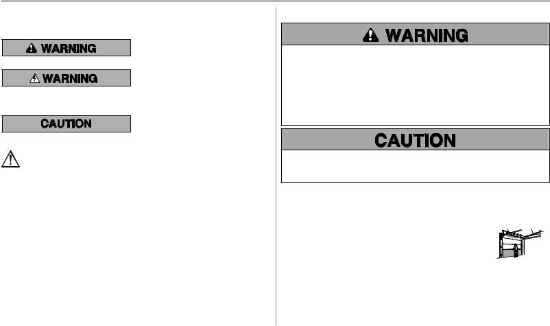
Safety Symbol and Signal Word Review
This garage door opener has been designed and tested to offer safe service provided it is installed, operated, maintained and tested in strict accordance with the instructions and warnings contained in this manual.
When you see these Safety Symbols and Signal Words on the following pages, they will alert you to the possibility of
Mechanical seriousinjuryor death if you do not comply with the warnings that accompany them. The hazard may come
from something mechanical or from electric shock. Read
the warnings carefully.
Electrical
When you see this Signal Word on the following pages, it will alert you to the possibility of damage to your garage door and/or the garage door opener if you do not comply with the cautionary statements that accompany it. Read them carefully.
WARNING: This product can expose you to chemicals including lead, which are known to the State of California to cause cancer or birth defects or other reproductive harm. For more information go to www.P65Warnings.ca.gov
Unattended Operation
The Timer-to-Close (TTC) feature, the MyQ® Smartphone Control app, and MyQ® Garage Door and Gate Monitor are examples of unattended close and are to be used ONLY with sectional doors. Any device or feature that allows the door to close without being in the line of sight of the door is considered unattended close. The Timer-to-Close (TTC) feature, the MyQ® Smartphone Control, and any other MyQ® devices are to be used ONLY with sectional doors.
Check the Door
To prevent possible SERIOUS INJURY or DEATH:
•ALWAYS call a trained door systems technician if garage door binds, sticks, or is out of balance. An unbalanced garage door may NOT reverse when required.
•NEVER try to loosen, move or adjust garage door, door springs, cables, pulleys, brackets or their hardware, ALL of which are under EXTREME tension.
•Disable ALL locks and remove ALL ropes connected to garage door BEFORE installation and operating garage door opener to avoid entanglement.
•DO NOT install on a one-piece door if using devices or features providing unattended close. Unattended devices and features are to be used ONLY with sectional doors.
To prevent damage to garage door and opener:
•ALWAYS disable locks BEFORE installing and operating the opener.
•ONLY operate garage door opener at 120V, 60 Hz to avoid malfunction and damage.
Before you begin:
1.Disable locks and remove any ropes connected to the garage door.
2.Lift the door halfway up. Release the door. If balanced, it should stay in place, supported entirely by its springs.
3.Raise and lower the door to check for binding or sticking. If your door binds, sticks, or is out of balance, call a trained door systems technician.
4.Check the seal on the bottom of the door. Any gap between the floor and the bottom of the door must not exceed 1/4 inch (6 mm). Otherwise, the safety reversal system may not work properly.
5.The opener should be installed above the center of the door. If there is a torsion spring or center bearing plate in the way of the header bracket, it may be installed within 4 feet (1.2 m) to the left or right of the door center. See page 12.
Torsion Extension
Spring OR Spring
2
Preparation
Additional Items You May Need: |
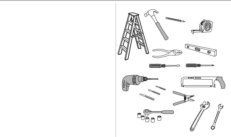
Tools Needed |
Survey your garage area to see if you will need any of the following items:
n (2) 2X4 PIECES OF WOOD
May be used to fasten the header bracket to the structural supports. Also used to position the garage door opener during installation and for testing the safety reversing sensors.
n SUPPORT BRACKET AND FASTENING HARDWARE
Must be used if you have a finished ceiling in your garage.
n EXTENSION BRACKETS (MODEL 041A5281-1) OR WOOD BLOCKS
Depending upon garage construction, extension brackets or wood blocks may be needed to install the safety reversing sensor.
nFASTENING HARDWARE
Alternate floor mounting of the safety reversing sensor will require hardware not provided.
nDOOR REINFORCEMENT
Required if you have a lightweight steel, aluminum, fiberglass or glass panel door.
n RAIL EXTENSION KIT |
5/32 |
Required if your garage door is more than 7 feet (2.13 m) high. |
3/16 |
5/16
1/2
5/8 |
|
1/4 |
|
|
|
7/16 |
9/16 |
7/16 |
|
|
3
Preparation
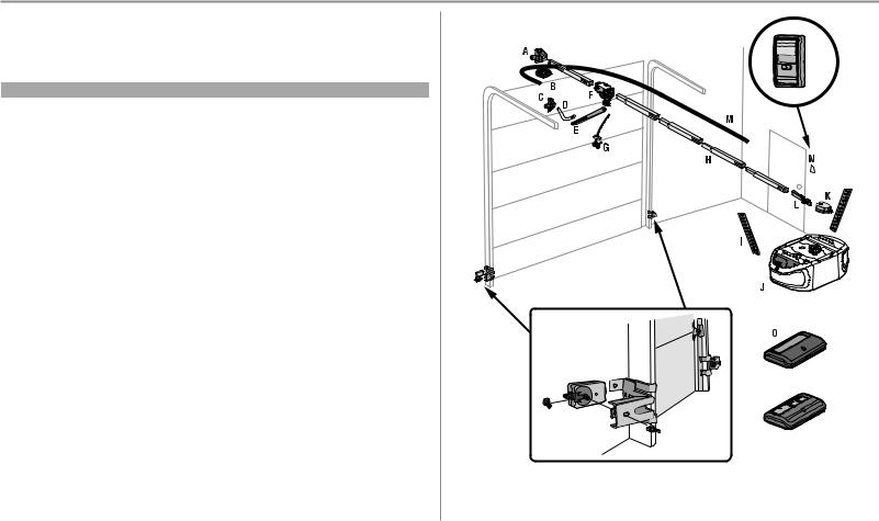
Carton Inventory
Save the carton and packing material until the installation and adjustment is complete. Instructions for the accessories will be attached to the accessory and are not included in this manual. The images throughout this manual are for reference only and your product may look different.
Model |
Power |
Door Control |
Remote Control |
Wireless Keypad |
B500 |
Med Lift Power System™ |
Multi-Function |
1-button (2) |
|
B503 |
Med Lift Power System™ |
Multi-Function |
3-button (2) |
|
B510 |
Med Lift Power System™ |
Multi-Function |
3-button (2) |
ü |
A. |
Header bracket |
|
|
|
B. |
Pulley |
|
|
|
C. |
Door bracket |
|
|
|
D. |
Curved door arm |
|
|
|
E. |
Straight door arm (Packaged inside front rail section) |
|
|
|
F. |
Trolley |
|
|
|
|
NOTE: Be sure to assemble the trolley before sliding onto rail. |
|
||
G. |
Emergency release rope and handle |
|
|
|
H. |
Rail (1 front and 4 center sections) |
|
|
|
I. |
Hanging brackets (2) (Packaged inside the front rail section) |
|
||
J. |
Garage door opener (motor unit) |
|
|
|
K. |
Sprocket cover and screws |
|
|
|
L.“U” bracket
M. |
Belt |
P |
N. |
Door control |
|
O. |
Remote control |
|
P. |
The Protector System® |
|
|
Safety reversing sensors with 2 conductor white and white/black wire attached: Sending Sensor (1), |
|
|
Receiving Sensor (1), and Safety Sensor Brackets (2) |
OR |
NOT SHOWN
Wireless Keypad
White and red/white wire
Owner's manual
Hardware
4

Preparation
Hardware
ASSEMBLY
Bolt |
Bolt |
1/4"-20x1-3/4" |
|
 Threaded
 Shaft with
 Spring
 Trolley Nut
Master Link
Hex Screw #8x3/8" (2) Lock Washer 3/8" (packed with the
sprocket cover)
Nut 3/8" |
Lock Nut |
|
1/4"-20 |
||
|
INSTALLATION
Lag Screw 5/16"-9x1-5/8" (4)
Clevis Pin 5/16"x1-1/2"
Clevis Pin 5/16"x1"
Hex Bolt 5/16"-18x7/8" (4)
Lock Washer Nut 5/16"-18 (4)
5/16"-18 (4)
Wing Nut 1/4"-20 (2)
Self-Threading Screw 1/4"-14x5/8" (2)
Clevis Pin 5/16"x1-1/4"
Carriage Bolt 1/4"-20x1/2" (2)
Ring
Fastener (3)
DOOR CONTROL
Drywall Anchors (2)
Screw 6-32x1" (2)
Screw 6ABx1" (2)
Insulated Staples
(Not Shown)
5
Assembly
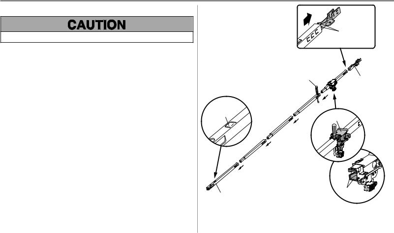
STEP 1 Assemble the rail and install the trolley
To prevent INJURY from pinching, keep hands and fingers away from the joints while assembling the rail.
To avoid installation difficulties, do not run the garage door opener until instructed to do so.
The front rail has a cut out “window” at the door end. The rail tab MUST be on top of the rail when assembled.
1.Remove the straight door arm and hanging bracket packaged inside the front rail and set aside for Installation Step 5 and 9. NOTE: To prevent INJURY while unpacking the rail carefully remove the straight door arm stored within the rail section.
2.Align the rail sections on a flat surface as shown and slide the tapered ends into the larger ones. Tabs along the side will lock into place.
3.Place the motor unit on packing material to protect the cover, and rest the back end of the rail on top. For convenience, put a support under the front end of the rail.
4.As a temporary stop, insert a screwdriver into the hole in the second rail section from the motor unit, as shown.
5.Check to be sure there are 4 plastic wear pads inside the inner trolley. If they became loose during shipping, check all packing material. Snap them back into position as shown.
6.Slide the trolley assembly toward the screwdriver as shown.
7.Slide the rail onto the “U” bracket, until it reaches all the stops on the top and sides of the “U” bracket.
Slide to stops on top and sides of “U” bracket
Screwdriver |
“U” BRACKET |
|
|
|
(TO MOTOR UNIT) |
Rail Tab
On Top
Trolley
Wear
FRONT RAIL SECTION
(TO DOOR)
6
Assembly
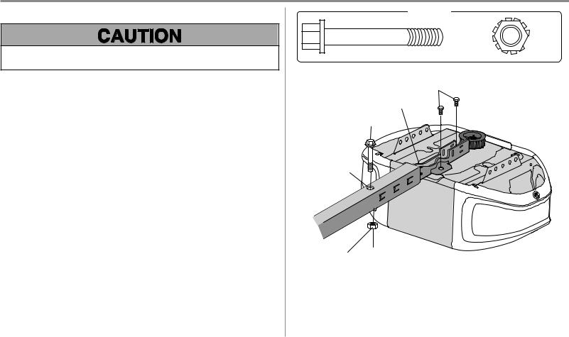
STEP 2 Fasten the rail to the motor unit
To avoid SERIOUS damage to garage door opener, use ONLY those bolts/fasteners mounted in the top of the opener.
1.Insert a 1/4"-20 x 1-3/4" bolt into the cover protection bolt hole on the back end of the rail as shown. Tighten securely with a 1/4"-20 lock nut. DO NOT overtighten.
2.Remove the bolts from the top of the motor unit.
3.Use the carton to support the front end of the rail.
4.Place the “U” bracket, flat side down onto the motor unit and align the bracket holes with the bolt holes.
5.Fasten the “U” bracket with the previously removed bolts; DO NOT use any power tools. The use of power tools may permanently damage the garage door opener.
HARDWARE
Bolt 1/4"-20x1-3/4"
Bolts (Mounted in the garage door opener)
“U” Bracket
Bolt
Cover Protection
Bolt Hole
Lock Nut
Lock Nut  1/4"-20
7
Assembly
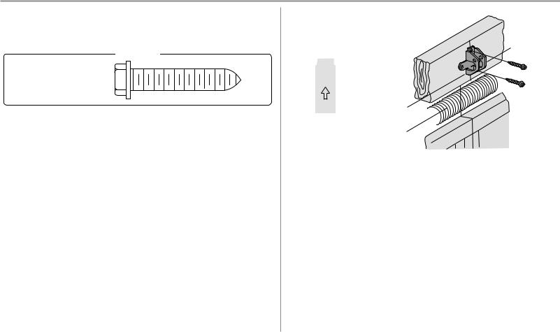
STEP 3 Install the idler pulley
1.Lay the belt beside the rail, as shown. Grasp the end with the hooked trolley connector and pass approximately 12" (30 cm) of belt through the window. Keep the ribbed side toward the rail, and allow it to hang until Assembly Step 4.
2.Remove the tape from the idler pulley. The inside center should be pre-greased. If dry, regrease to ensure proper operation.
3.Place the idler pulley into the window as shown.
4.Insert the idler bolt from the top through the rail and pulley. Tighten with a 3/8" lock washer and nut underneath the rail until the lock washer is compressed.
5.Rotate the pulley to be sure it spins freely.
6.Locate the rail tab. The rail tab is between the idler bolt and the trolley in the front rail section. Use a flathead screwdriver and lift the rail tab until the tab is vertical (90º).
HARDWARE
Nut 3/8" |
Lock Washer 3/8" |
Bolt |
|
Rail Tab
Belt
Rail
|
Bolt |
|
Grease Inside |
|
Pulley |
Lock Washer |
Idler Pulley |
Nut |
Trolley Connector |
8
Assembly
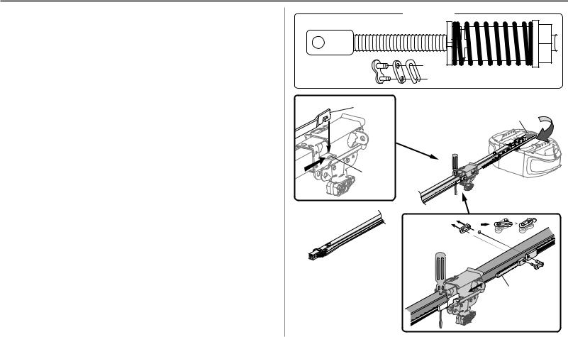
STEP 4 Install the belt
1.Pull the belt around the idler pulley and toward the trolley. The ribbed side must contact the pulley.
2.Hook the trolley connector into the retaining slot on the trolley as shown (Figure 1).
3.With the trolley against the screwdriver, dispense the remainder of the belt along the rail length toward the motor unit and around the sprocket (Figure 2). The sprocket teeth must engage the belt.
4.Check to make sure the belt is not twisted. Connect the trolley threaded shaft with the master link (Figure
3).
• Push pins of master link bar through holes in end of belt and trolley threaded shaft. • Push master link cap over pins and past pin notches.
• Slide the closed end of the clip-on spring over one of the pins. Push the open end of the clip-on spring
onto the other pin.
5.Remove the spring trolley nut from the threaded shaft.
6.Insert the trolley threaded shaft through the hole in the trolley.
HARDWARE
Threaded Shaft with Spring Trolley Nut
|
Master Link |
|
|
FIGURE 1 |
Trolley |
FIGURE |
2 |
|
Connector |
||
|
Sprocket |
|
|
|
|
|
|
|
Retaining |
|
|
|
Slot |
|
|
Master Link

Threaded Shaft
FIGURE 3
9
Assembly
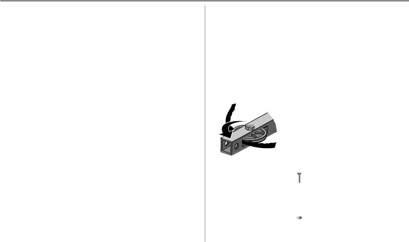
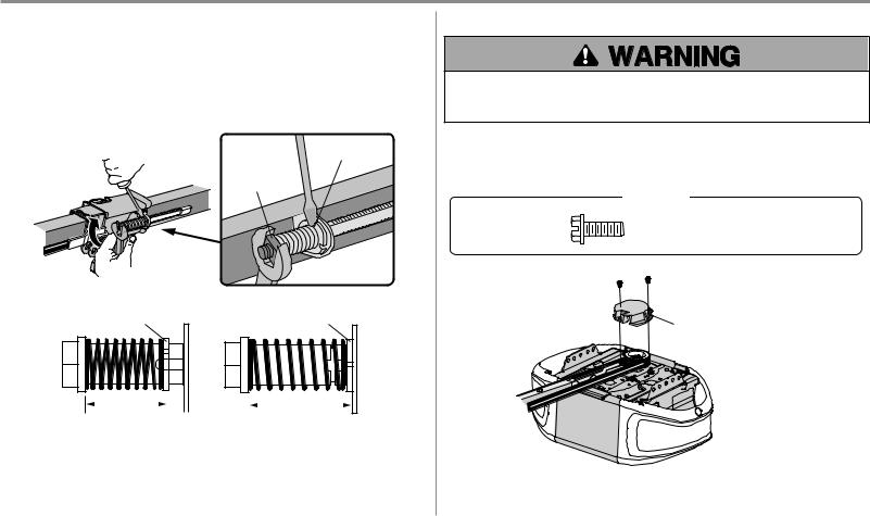
STEP 5 Tighten the belt
1.By hand, thread the spring trolley nut on the threaded shaft until it is finger tight against the trolley. Do not use any tools. Remove the screwdriver.
2.Insert a flathead screwdriver tip into one of the nut ring slots and brace it firmly against the trolley.
3.Tighten the spring trolley nut with an adjustable wrench or a 7/16" open end wrench about a quarter turn until the spring releases and snaps the nut ring against the trolley. This sets the spring to optimum belt tension.
Nut Ring Slot
Spring
Trolley Nut
Nut Ring |
Nut Ring |
|
|
|
|
|
BEFORE |
|
|
|
|
|
|
|
|
|
|
|
|
|
|
|
|
|
AFTER |
|
|
|
|
|
|
|
|
|
|
|
||
1" (2.5 cm) |
|
|
|
|
1-1/4" (3.18 cm) |
|||||
STEP 6 Install the sprocket cover
To avoid possible SERIOUS INJURY to finger from moving garage door opener:
•ALWAYS keep hand clear of sprocket while operating opener.
•Securely attach sprocket cover BEFORE operating.
1.Position the sprocket cover over the sprocket as shown and fasten to the mounting plate with 8x3/8" hex screws provided.
You have now finished assembling your garage door opener. Please read the following warnings before proceeding to the installation section.
HARDWARE
Hex Screw #8x3/8"
(Packed with the sprocket cover)
 Hex Screw #8x3/8"
Sprocket Cover
10
Installation
Change 5. to say "Where possible, install the door opener 7 feet (2.13 m) or more above the floor." per regulatory Bill Carrey.
IMPORTANT INSTALLATION INSTRUCTIONS
To reduce the risk of SEVERE INJURY or DEATH:
1.READ AND FOLLOW ALL INSTALLATION WARNINGS AND INSTRUCTIONS.
2.Install garage door opener ONLY on properly balanced and lubricated garage door. An improperly balanced door may NOT reverse when required and could result in SEVERE INJURY or DEATH.
3.ALL repairs to cables, spring assemblies and other hardware MUST be made by a trained door systems technician BEFORE installing opener.
4.Disable ALL locks and remove ALL ropes connected to garage door BEFORE installing opener to avoid entanglement.
5.Where possible, install the door opener 7 feet (2.13 m) or more above the floor.
6.Mount the emergency release within reach, but at least 6 feet (1.83 m) above the floor and avoiding contact with vehicles to avoid accidental release.
7.NEVER connect garage door opener to power source until instructed to do so.
8.NEVER wear watches, rings or loose clothing while installing or servicing opener. They could be caught in garage door or opener mechanisms.
Step 11. changed "manual" to "emergency" label. Per Bill C. regulatory. Updated in 114A5010 MDR. Updated in 114A4862, 114A5051. -LTB
9. Install wall-mounted garage door control:
•within sight of the garage door.
•out of reach of small children at a minimum height of 5 feet (1.5 m) above floors, landings, steps or any other adjacent walking surface.
•away from ALL moving parts of the door.
10.Place entrapment warning label on wall next to garage door control.
11.Place emergency release/safety reverse test label in plain view on inside of garage door.
12.Upon completion of installation, test safety reversal system. Door MUST reverse on contact with a 1-1/2" (3.8 cm) high object (or a 2x4 laid flat) on the floor.
13.To avoid SERIOUS PERSONAL INJURY or DEATH from electrocution, disconnect ALL electric power BEFORE performing ANY service or maintenance.
14.DO NOT install on a one-piece door if using devices or features providing unattended close. Unattended devices and features are to be used ONLY with sectional doors.
11

Installation
STEP 1 Determine the header bracket location |
Header Wall |
|
OPTIONAL CEILING MOUNT |
|
FOR HEADER BRACKET |
||
|
Vertical Centerline of Garage Door |
||
|
2x4 |
Structural |
|
|
|
|
|
|
|
Supports |
Unfinished |
|
|
|
|
To prevent possible SERIOUS INJURY or DEATH: |
|
|
Ceiling |
|
|
|
|
• Header bracket MUST be RIGIDLY fastened to structural support on header wall or ceiling, otherwise |
|
|
|
garage door might NOT reverse when required. DO NOT install header bracket over drywall. |
|
|
|
• Concrete anchors MUST be used if mounting header bracket or 2x4 into masonry. |
|
|
|
• NEVER try to loosen, move or adjust garage door, springs, cables, pulleys, brackets, or their hardware, ALL |
Level |
|
|
of which are under EXTREME tension. |
|
|
|
• ALWAYS call a trained door systems technician if garage door binds, sticks, or is out of balance. An |
(Optional) |
|
2x4 |
unbalanced garage door might NOT reverse when required. |
|
|
|
Installation procedures vary according to garage door types. Follow the instructions which apply to your door.
1. |
Close the door and mark the inside vertical centerline of the garage door. |
Sectional door with curved track |
One-piece door with horizontal track |
||
2. |
Extend the line onto the header wall above the door.You can fasten the header bracket within 4 feet (1.22 m) |
||||
|
|
|
|||
|
of the left or right of the door center only if a torsion spring or center bearing plate is in the way; or you can |
Header Wall |
|
Header Wall |
|
|
attach it to the ceiling (see page 13) when clearance is minimal. (It may be mounted on the wall upside |
|
|||
|
2" (5 cm) |
|
2" (5 cm) |
||
|
down if necessary, to gain approximately 1/2" (1 cm). If you need to install the header bracket on a 2x4 (on |
|
|||
|
|
|
|
||
|
wall or ceiling), use lag screws (not provided) to securely fasten the 2x4 to structural supports as shown |
Track |
Door |
Track |
|
|
|
||||
|
here and on page 13. |
Highest |
|
Highest |
|
3. |
Open your door to the highest point of travel as shown. Draw an intersecting horizontal line on the header |
Point of |
|
||
|
wall 2" (5 cm) above the high point: |
Travel |
|
Point of |
|
|
|
Door |
|
Travel |
|
• 2" (5 cm) above the high point for sectional door and one-piece door with track. • 8" (20 cm) above the high point for one-piece door without track.
This height will provide travel clearance for the top edge of the door. NOTE: If the total number of inches exceeds the |
One-piece door without track: |
One-piece door without track: |
|
height available in your garage, use the maximum height possible, or refer to page 13 for ceiling installation. |
|||
jamb hardware |
pivot hardware |
||
|
|
Header Wall |
|
Header Wall |
|
|
8" (20 cm) |
|
|
8" (20 cm) |
|
|
|
|
|
|
Door |
Highest |
|
Highest |
|
Door |
||
|
Point of |
||
|
Point of |
||
|
|
||
|
|
Travel |
|
|
Travel |
|
|
Jamb |
|
|
|
|
|
|
|
Hardware |
|
|
Pivot |
|
|
|
12
Installation
STEP 2 Install the header bracket
You can attach the header bracket either to the wall above the garage door, or to the ceiling. Follow the instructions which will work best for your particular requirements. Do not install the header bracket over drywall. If installing into masonry, use concrete anchors (not provided).
HARDWARE
LAG SCREW 5/16"-9X1-5/8"
OPTIONAWALLINSTALLATION
1.Center the bracket on the vertical centerline with the bottom edge of the bracket on the horizontal line as shown (with the arrow pointing toward the ceiling).
2.Mark the vertical set of bracket holes. Drill 3/16" pilot holes and fasten the bracket securely to a structural support with the hardware provided.
OPTIONBCEILING INSTALLATION
1.Extend the vertical centerline onto the ceiling as shown.
2.Center the bracket on the vertical mark, no more than 6" (15 cm) from the wall. Make sure the arrow is pointing away from the wall. The bracket can be mounted flush against the ceiling when clearance is minimal.
3.Mark the side holes. Drill 3/16" pilot holes and fasten bracket securely to a structural support with the hardware provided.
WALL INSTALLATION |
|
|
|
|
|
Header Wall |
Vertical |
|
|
|
|
|
2x4 |
|
Centerline of |
Wall Mounting |
Structural |
|
Garage Door |
Holes |
Support |
|
|
|
|
Header |
|
|
|
Bracket |
Lag |
UP |
|
|
|
Horizontal |
|
Screw |
|
|
Line |
|
|
|
|
|
Door |
|
Highest Point |
|
Spring |
|
|
|
|
Optional Mounting |
of Garage |
|
|
Holes |
Door Travel |
|
|
|
|
|
Garage Door |
CEILING INSTALLATION |
|
|
|
|
Header |
|
|
|
Bracket |
|
Finished Ceiling |
|
|
|
|
|
6" (15 cm) |
|
|
Ceiling Mounting |
Maximum |
|
|
|
|
|
|
Holes |
|
|
|
|
Door Spring |
|
|
|
|
|
Vertical |
|
|
|
Centerline of |
UP |
|
|
Garage Door |
|
|
|
Lag Screw |
|
|
Garage Door |
Header Wall |
|
|
|
13
Installation
STEP 3 Attach the rail to the header bracket
1.Position the opener on the garage floor below the header bracket. Use packing material as a protective base.
NOTE: If the door spring is in the way, you will need help. Have someone hold the opener securely on a temporary support to allow the rail to clear the spring.
2.Position the rail bracket against the header bracket.
3.Align the bracket holes and join with a clevis pin as shown.
4.Insert a ring fastener to secure.
HARDWARE
Clevis Pin
Ring Fastener
5/16"x1-1/2"
Ring Fastener
Clevis Pin
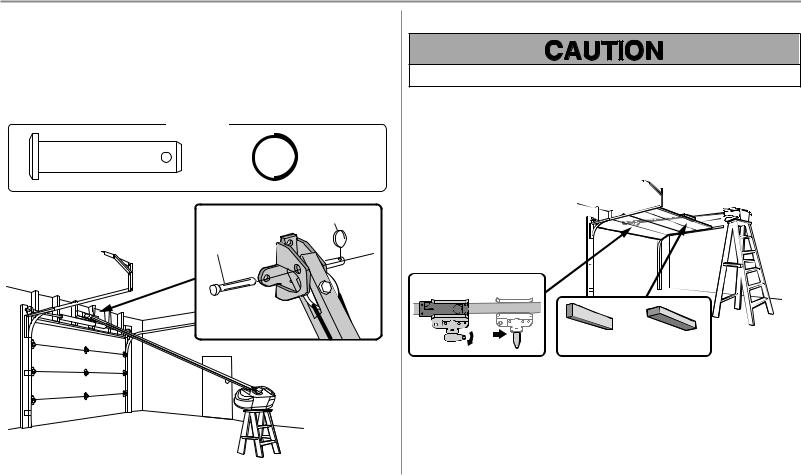
STEP 4 Position the garage door opener
To prevent damage to garage door, rest garage door opener rail on 2x4 placed on top section of door.
1.Remove the packing material and lift the garage door opener onto a ladder.
2.Fully open the door and place a 2x4 (laid flat) under the rail. For one-piece doors without tracks, lay the 2x4 on it's side.
NOTE: A 2x4 is ideal for setting the distance between the rail and the door. If the ladder is not tall enough you will need help at this point. If the door hits the trolley when it is raised, pull the trolley release arm down to disconnect the inner and outer trolley. Slide the outer trolley toward the garage door opener. The trolley can remain disconnected until instructed.
Connected Disconnected
2x4 |
2x4 |
One-piece door |
All other |
without tracks |
door types |
|
|
14
Installation
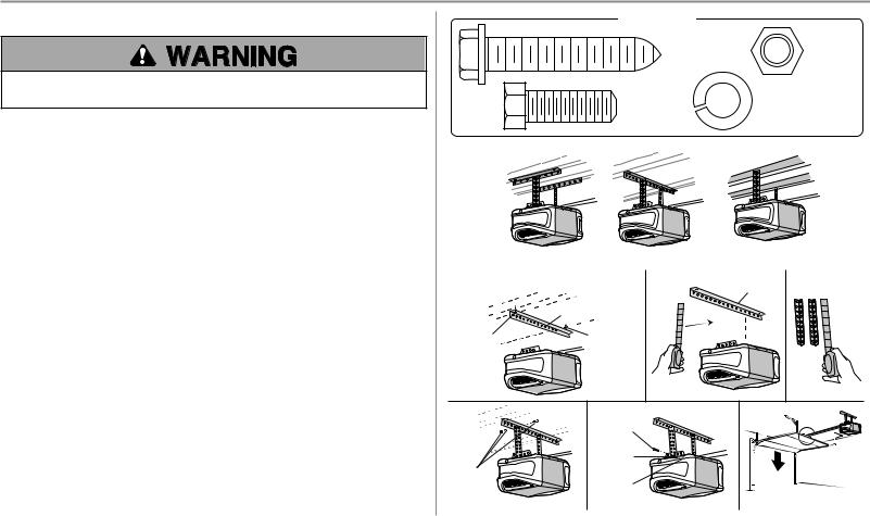
STEP 5 Hang the garage door opener
To avoid possible SERIOUS INJURY from a falling garage door opener, fasten it SECURELY to structural supports of the garage. Concrete anchors MUST be used if installing ANY brackets into masonry.
Hanging the garage door opener will vary depending on your garage. Below are three example installations. Your installation may be different. For ALL installations the garage door opener MUST be connected to structural supports. The instructions illustrate one of the examples below.
1.On finished ceilings, use the lag screws to attach a support bracket (not provided) to the structural supports before installing the garage door opener.
2.Make sure the garage door opener is aligned with the header bracket. Measure the distance from each side of the garage door opener to the support bracket.
3.Cut both pieces of the hanging bracket to required lengths.
4.Attach the end of each hanging bracket to the support bracket with appropriate hardware (not provided).
5.Attach the garage door opener to the hanging brackets with the hex bolts, lock washers, and nuts.
6.Remove the 2x4 and manually close the door. If the door hits the rail, raise the header bracket.
HARDWARE
Lag Screw |
Nut |
|
5/16"-18 |
||
5/16"-9x1-5/8" |
||
|
||
Hex Bolt |
Lock Washer |
|
5/16"-18 |
||
5/16"- 18x7/8" |
||
|
EXAMPLES
|
Finished Ceiling |
|
Unfinished Ceiling |
|
|
|
|
|
|
1 |
Finished Ceiling |
2 |
Not Provided |
3 |
|
|
|
||
Not Provided
Lag Screw  Lag Screw
4 |
5 |
6 |
|
Hex Bolt |
|
Lock |
|
Washer |
Not |
|
Provided |
Nut |
15
Loading...