


STAR250TM WIRELESS ACCESS CONTROL RECEIVER
SPECIFICATIONS
SUPPLY VOLTAGE: 12-24 VOLTS AC OR DC OPERATING CURRENT: 250 mA MAXIMUM OPERATING TEMP RANGE: -40 TO +149F
(-40 TO +65C)
FREQUENCY: 433.92
RELAY CONTACT RATING: 1 AMP @ 24 VOLTS AC OR DC
Removable memory modules and RF module are included in this product. Jumper J2 must remain in the default position unless otherwise noted. THERE ARE NO OTHER SERVICEABLE PARTS.
TABLE OF CONTENTS |
|
DESCRIPTION |
|
PAGE |
|
Mounting Instructions for STAR250................... |
1 |
Programming For STAR250........................... |
2 & 3 |
STAR250 Features............................................. |
4 |
Electrical Connections for STAR250.................. |
4 |
PATENTS PENDING
 WARNING
To prevent possible SERIOUS INJURY or DEATH from electrocution:
• Be sure power is not connected BEFORE installing the receiver.
To prevent possible SERIOUS INJURY or DEATH from a moving gate or garage door:
•ALWAYS keep remote controls out of reach of children. NEVER permit children to operate, or play with remote control transmitters.
•Activate gate of door ONLY when it can be seen clearly, is properly adjusted, and there are no obstructions to door travel.
•ALWAYS keep gate or garage door in sight until completely closed. NEVER permit anyone to cross path of moving gate or door.
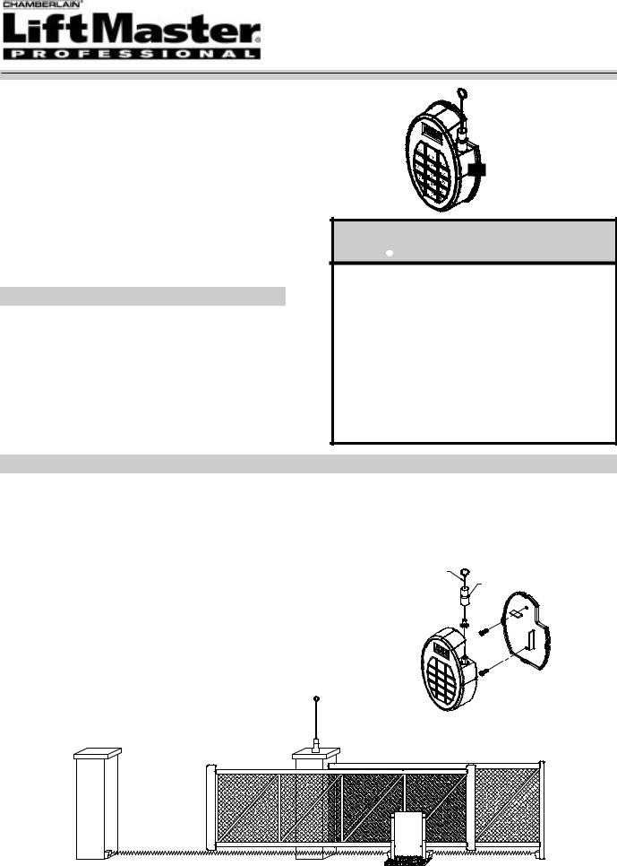
MOUNTING INSTRUCTIONS FOR STAR250
Location: Select a convenient location near your device to be controlled by the STAR250. For best performance, the STAR250 should be mounted in Line-Of-Sight with your intended transmitting location. Avoid mounting the STAR250 in or on metallic enclosures. If this is unavoidable, we recommend installing the antenna extension kit (86LM) for best results. See Remote Antenna Mounting for proper installation.
Receiver Mounting: Mount Backplate to desired surface using M3 hardware (not supplied). Hardware used will depend on mounting application. (Refer to figure 1 for Receiver mounting hole locations). Wire electrical connections to unit. Snap Unit to Back Plate.
Direct Antenna Mounting: Install the supplied antenna onto the STAR250 antenna connector by screwing the connector clockwise. Slide the seal boot down to meet the O-Ring, covering the antenna hardware.
Remote Antenna Mounting: Use the optional 86LM antenna extension kit to mount the remote antenna as high and far from metal as possible for best radio range (See figure 2). Contact LiftMaster customer service to order the model 86LM.
FIGURE 1 ANTENNA
 SEAL BOOT
 ANTENNA
CONNECTOR
FIGURE 2
1
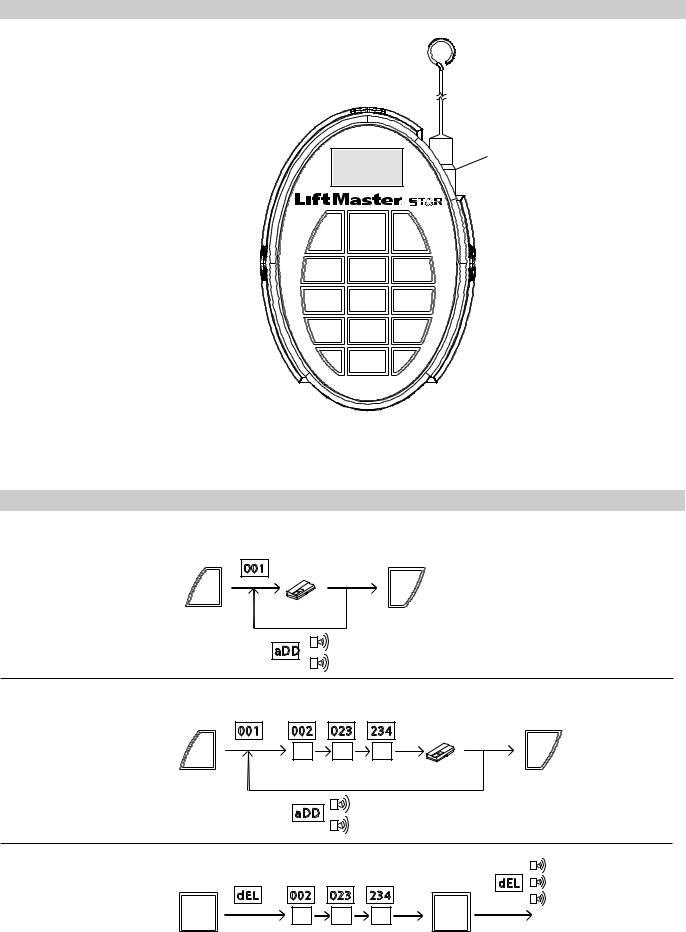
STAR250 FEATURES
DIGITAL DISPLAY
DISPLAYS TRANSMITTER LOCATION
NUMBERS WHEN PROGRAMMING OR
ACCESS IS GRANTED. ALSO DISPLAYS
USER PROMPTS AND MESSAGES.
DELETE KEY
USED TO DELETE A
TRANSMITTER FROM THE
SELECTED MEMORY LOCATION
ADD KEY
USED TO ENTER TRANSMITTERS
AND ENTER RAPID LEARNTM
MODE.
STAR KEY
USED TO ENTER ADVANCED FUNCTIONS: *,1- LAST TRANSMITTER RECEIVED
*,2- NO. OF UNUSED MEMORY LOCATIONS
*,3- NO. OF OCCUPIED MEMORY LOCATIONS
*,4- NO. OF BLOCKED TRANSMITTER LOCATIONS
*,5- FIRST BLOCKED TRANSMITTER LOCATION
*,7- SOFTWARE VER. #
*,0- AUDIBLE DIAGNOSTICS OFF/ON
Add Delete Block
1 2 3
4 5 6
7 8 9 * 0 #
POWER INDICATOR SCROLLING DASHES ON DIGITAL DISPLAY WHEN AC OR DC POWER IS APPLIED TO THE UNIT.
ANTENNA CONNECTION FOR CONNECTION TO THE DIRECT ANTENNA
OR THE ANTENNA EXTENSION KIT.
BLOCK KEY
USED TO BLOCK THE RECEIVER FROM GRANTING ACCESS TO THE SELECTED TRANSMITTER. TRANSMITTER REMAINS IN MEMORY, AND MAY BE UNBLOCKED IN THE FUTURE.
NUMERIC KEYPAD
USED FOR PROGRAMMING AND QUERYING TRANSMITTER LOCATIONS. ALSO USED TO ENTER ADVANCED FUNCTIONS.
POUND KEY
USED AS AN ESC OR EXIT KEY FOR ALL FUNCTIONS OR MODES.
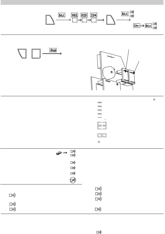
PROGRAMMING THE STAR250
Rapid LearnTM- Add transmitter to next available location.
AUTO
Add |
|
# |
TO EXIT |
|
|
|
|
PRESS |
PRESS |
PRESS |
|
|
|
Adding Transmitter- Add transmitter to a specific location.
|
AUTO |
|
|
|
|
|
Add |
2 |
3 |
4 |
|
# |
TO EXIT |
|
|
|
|
|
|
|
PRESS |
ENTER LOCATION (1-250) |
PRESS |
PRESS |
|
||
|
|
|
|
|
||
Deleting a Transmitter- To delete a user.
Delete |
2 |
3 |
4 |
END |
|
|
|
Delete |
|
|
ENTER LOCATION (1-250) |
PRESS |
||
PRESS
TO
CONFIRM
2
PROGRAMMING THE STAR250 (CON’T)
Blocking (Unblocking) a Transmitter- To block or unblock a user.
2 |
3 |
4 |
|
OR |
END |
Block |
|
||||
Block |
|
|
|
|
|
ENTER LOCATION (1-250) |
PRESS |
(UNBLOCK) |
|
||
PRESS
TO
CONFIRM
Duplicating Memory- Allows user to back up learned transmitter memory into the
provided backup memory module. Main Memory Module
* , |
|
6 |
END |
|
~6 SECONDS |
PRESS SIMULTANEOUSLY |
|
Note- To duplicate memory, plug memory module into back up slot and press *,6. Once duplication is complete, remove the backup memory module and store in a separate location.
Restoring Memory- To restore memory, simply place the duplicate memory module from the backup memory location in the main memory position.
Backup Memory
Module
Advanced Functions
Step 1. For advanced functions, press and hold the (*) key and a number key at the same time to select the corresponding advanced function. (See table at right for available functions.) Press the ‘#’ key to exit the function.
|
* |
|
|
1 |
|
|
|
Memory location of last transmitter received. * |
|
|
|
|
|
|
|
|
|
|
* |
|
|
2 |
|
|
# of open transmitter locations. |
|
|
|
|
|
|
|
|
|
|
|
* |
|
|
3 |
|
|
|
# of locations occupied. |
|
|
|
|
|
|
# of blocked transmitter locations. |
||
|
* |
|
|
4 |
|
|
||
|
|
|
|
|
|
|
First blocked transmitter location. |
|
|
|
|
5 |
|
|
|||
|
* |
|
|
|
|
|
|
|
|
|
|
|
|
|
|
Next blocked location (Repeat to scroll). |
|
|
|
|
|
|
5 |
|
||
|
|
|
|
|
|
|
|
|
*
 6 Duplicate memorySee Duplicating memory.
*
 7 Version #
#Press to exit functions.
* |
0 |
Audible diagnostics OFF/ON |
|
(LED will be displayed when OFF) |
*If no transmitters are programmed into the STAR250, then (---) will be displayed.
Audible Diagnostics
Step 1. Activate Transmitter. Step 2. Listen for beep.
(LED will be displayed when OFF)
Double BeepTransmitter is valid & learned into STAR250 accompanied by transmitter location display.
Slow BeepSecurity+ Transmitter (Not learned in STAR250).
Fast BeepBillion Code Transmitter (Not learned in STAR250).
Long BeepBlocked transmitter.
No BeepTransmitter not working.
Keypad Sound Alerts
Single BeepKey Pressed.
Double BeepConfirmation of an accepted Tx or valid Add/Block input.
Triple BeepConfirmation of Delete.
Long BeepBlocked Tx, Error, or Out of Range
Transmitter location Query
Step 1. Enter a transmitter location number (001-250) to view location status (See table to the right for possible status displays).
Display |
Description |
Beeper |
||
OPn |
Transmitter location is empty |
no beep |
||
Occ |
Transmitter location is occupied |
no beep |
||
bLc |
Transmitter location is blocked |
no beep |
||
Out |
Transmitter location is out of range |
long beep |
||
|
|
|
(not between 1 & 250) |
|
|
|
|
|
|
|
|
|
|
|
3

TROUBLESHOOTING GUIDE
Problem |
Probable Cause(s) |
Solution |
||
No Display |
1. |
Faulty/intermittent power connections to unit |
1. |
Check power connections to |
|
|
Or |
|
unit |
|
2. |
No power to unit |
2. |
Supply power to unit |
|
|
|
||
No Beep when |
Audible Diagnostics may have been turned OFF |
Press "*" and "0" keys at the same |
||
transmitting |
(right-most decimal point will be lit on the |
time. |
||
|
display) |
|
|
|
Transmitter does not |
1. |
Transmitter not learned into system |
1. |
Add transmitter to memory |
activate operator |
|
Or |
2. |
Pay your rent |
|
2. |
Transmitter is blocked |
3. |
Replace transmitter battery |
|
|
Or |
|
|
|
3. |
Transmitter battery is dead |
|
|
Transmitter won't learn |
1. |
Memory may be full |
1. |
Delete unused transmitters |
into memory |
|
Or |
|
from memory |
|
2. |
Transmitter may not be a recognized |
2. |
Verify transmitter is listed in |
|
|
Chamberlain transmitter |
|
compatible transmitters |
|
|
Or |
|
section |
|
3. |
Transmitter battery is dead |
3. |
Replace transmitter battery |
Unit does not function, |
Main memory module missing or damaged |
Replace Main memory module |
||
[E 1] displayed |
|
|
|
|
Duplication function does |
Backup memory module missing or damaged- |
Replace Backup memory module |
||
not work, |
If included |
|
|
|
[E 2] displayed |
|
|
|
|
Keypad does not respond, |
Keypad has a stuck key |
Cycle power. |
||
[E 3] displayed |
|
|
If unit exhibits this condition |
|
|
|
|
again after 2 minutes, contact |
|
|
|
|
Technical Service |
|
ELECTRICAL CONNECTIONS FOR STAR250
RECEIVER (Bottom)
24V-12 .O.N RELAY
AC/DC CONTACT COM
|
|
|
|
To wall |
Model 23024E |
||
outlet |
Transformer |
||
GB
www.liftmaster.com
info@chamberlaingroup.com
STAR250 COMPATIBLE TRANSMITTERS
Transmitters
4330E
4332E
4333E
4335E
Keypads
747E
STAR250 OPTIONAL ACCESSORIES
CGI Part Number |
Description |
|
|
|
|
|
041A2743X |
Watertight Box Field Install Kit |
|||||
|
86LM |
Antenna Extension Kit |
||||
|
23024E |
Transformer 230V/24V/AC |
||||
|
|
|
|
|
|
|
|
|
D e c l a r a t i o n o f C o n f o r m i t y |
||||
|
Universal Radio Receiver.....................................Model No. Star250-xxx |
|||||
|
are in conformity to the applicable sections of Standards .ETS 300 683, |
|||||
|
per the provisions & all amendments of the EU Directives ....1999/5/EC |
|||||
|
|
D e c l a r a t i o n o f I n c o r p o r a t i o n |
||||
|
Universal Radio Receiver Model No. Star250-433, when installed and |
|||||
|
maintained according to all the Manufacturer’s instructions in combination |
|||||
|
with a Gate or Garage Door System, which have also been installed and |
|||||
|
maintained according to all the Manufacturer’s instructions, meets the pro- |
|||||
|
visions of EU Directive 98/37/EC |
and all ammendments. |
||||
|
I, the undersigned, hereby declare that the equipment specified |
|||||
|
above and any accessory listed in the manual conforms to the |
|||||
|
|
|
above Directives and Standards. |
|||
|
Chamberlain GmbH |
|
|
|
|
|
|
|
|
|
|
||
|
D-66793 Saarwellingen |
|
Colin B. Willmott |
|
|
|
|
|
|
||||
|
September 2002 |
|
|
Chefingenieur |
|
|
|
|
|
|
|
|
|
|
|
|
|
|
|
|
4
STAR250TM
UNIVERSALEMPFÄ NGER FÜ R
250 HANDSENDER
SPEZIFIKATIONEN
NETZSPANNUNG: 12-24 VOLT AC ODER DC BETRIEBSSTROM: MAXIMAL 250 mA
ZULÄ SSIGE BETRIEBSTEMPERATUR: (-40 BIS +65C) FREQUENZ: 433,92
LEISTUNG RELAISKONTAKT: 1AMP @ 24 VOLT AC ODER DC
Dieses Produkt verfügt über herausnehmbare Speichermodule und ein Radiofrequenz-Modul. Sofern keine anderen Angaben gemacht werden, muss Jumper J2 in der werkseitig eingestellten Standardstellung verbleiben.
ALLE SONSTIGEN TEILE SIND WARTUNGSFREI.
INHALTSVERZEICHNIS |
|
TITEL |
|
SEITE |
|
Montage des STAR250....................................... |
1 |
Programmierung des STAR250.......................... |
2 & 3 |
STAR250 –Features............................................ |
4 |
STAR250 –Elektroanschlüsse............................. |
4 |
ZUM PATENT
ANGEMELDET
 WARNUNG
Zur Vermeidung SCHWERER VERLETZUNGEN bzw. TOD durch Elektroschock:
• ist VOR dem Installieren des Empfängers sicherzustellen, dass die Stromversorgung abgeschaltet ist.
Zur Vermeidung SCHWERER VERLETZUNGEN bzw. TOD aufgrund eines sich bewegenden Tores:
•sind Fernsteuerungen STETS außerhalb der Reichweite von Kindern aufzubewahren. Kindern darf die Bedienung bzw. das Spielen mit Fernsteuerungssendern UNTER KEINEN UMSTÄNDEN erlaubt werden.
•darf das Tor NUR bedient werden, wenn es sich in Sichtweite befindet, sachgemäß installiert wurde und sich im Torweg keine Hindernisse befinden.
•ist STETS bis zum vollständigen Schließen Blickkontakt zum Tor zu halten und darf NIEMANDEM der Aufenthalt im Laufoder Schwenkbereich des Tores gestattet werden.
MONTAGE DES STAR250
Standort: Wählen Sie einen passenden Ort nahe der Einrichtung, die vom STAR250 gesteuert werden soll. Das beste Ergebnis erzielen Sie, wenn der STAR250 in Sichtweite des von Ihnen vorgesehenen Sendeortes montiert wird. Der
STAR250 sollte möglichst nicht in oder auf Metallgehäusen montiert werden. Ist dies dennoch unvermeidbar, empfehlen wir zur Verbesserung der Leistung die Installation unserer speziellen Antennenverlängerung (86LM). Sachgemäß e Installation siehe unter "Montage mit Fernantennenanschluss".
Montage des Empfä ngers: Rückplatte mit M3-Schrauben (nicht im Lieferumfang enthalten) auf gewünschte Oberfläche montieren. Welche Schrauben Sie verwenden, hängt von der Befestigungsoberfläche ab (Montagelöcher des Empfängers siehe Abb. 1). Elektrokabel an Gerät anschließ en. Gerät durch Einschnappen auf Rückplatte befestigen.
Montage mit Direktantennenanschluss: Die mitgelieferte Antenne wird durch Festdrehen im Uhrzeigersinn am Antennenanschluss des STAR250 montiert. Zum Schutz des Antennenanschlusses Schutzkappe bis zum O-Ring herunterschieben.
Montage mit Fernantennenanschluss: Um einen besseren Funkempfang zu gew hrleisten, montieren Sie mit Hilfe der optionalen Antennenverl ngerung 86LM die Fernantenne so hoch und so weit vom Metall entfernt wie m glich (siehe Abb. 2). Das Modell 86LM erhalten Sie beim LiftMaster Kundenservice.
ABB. 1 |
ANTENNE |
|
SCHUTZKAPPE |
 ANTENNENANSCHLUSS
ABB. 2
5
 Loading...