


CB1
INT
D
GB
F
NL
Int. Service (+49) 6838/907 172
for service (+44) 0845 602 4285 pour service 03 87 95 39 28 voor service 020 684 7978
|
|
|
0678 |
|||
www.liftmaster.com |
||||||
Email: info@chamberlain.com |
|
|
|
|
|
|
|
|
|
|
|
|
|
|
|
|
|
|
|
|
709236B - 05.2004 |
|
|
|
|
|
|
|
|
|
|
|
||
|
|
|
|
|
||
STEUERUNG
Der Anschluß der Steuerung soll erst als letztes erfolgen,
d.h. Motoren befestigen, benötigte Kabel verlegen und Lichtschranken oder Kontaktleisten befestigen. Bei ortsfester Montage ist ein Mittel zur Trennung vom Netz erforderlich, das einen Kontaktabstand von min.
3mm besitzt (Hauptschalter).
Erläuterung: Relaiskontakte werden in dieser Anleitung als
NC (normal closed) oder NO (normal open) bezeichnet.
•NC Kontakte sind geschlossen und Öffnen
•NO Kontakte sind offen und schließen
Feuchtigkeit und Wasser zerstören die Steuerung. Stellen Sie unter allen Umständen sicher, dass Wasser, Feuchtigkeit oder Staunässe nicht in die Steuerung gelangen kann. Alle Öffnungen und Kabeldurchführungen müssen unbedingt wasserdicht verschlossen sein.
ELEKTRISCHE INSTALLATION
Montage der Steuerungsbox: Bei der Motorsteuerung handelt es sich um eine mikroprozessorgesteuerte Elektronik mit modernster Technik. Sie hat alle für den sicheren Betrieb notwendigen Anschlussmöglichkeiten und Funktionen.
Die Steuerbox mit der Motorsteuerung ist mit den Kabeldurchführungen nach unten zu montieren. Sie darf direkter Sonneneinstrahlung nicht dauernd ausgesetzt sein.
Mit der Elektronik läßt sich die Zugund Druckkraft sehr genau einstellen. Das Tor läßt sich bei richtiger Montage/Einstellung von Hand festhalten.
Während des Laufes kann das Tor jederzeit per Funk, Taster oder Schlüsselschalter gestoppt werden.
Der Torflügel benötigt für “AUF” und “ZU” Stellung einen stabilen Anschlag, da die Torantriebe keine Endschalter besitzen.
Stromverteilung: Das vom Antriebsarm führende Kabel muss in eine handelsübliche, wasserdichte Verteilungsdose geführt werden. Von der Verteilerdose bis zur Steuerung kann dann eine feste Kabelverlegung erfolgen. Oftmals ist es möglich, den einen Antrieb der direkt neben der Steuerung befestigt wird, direkt in die Box zu leiten. Legen Sie niemals Verteilungsdosen unter die Erde.
Folgende Kabelquerschnitte sollten generell nicht unterschritten werden:
100-230Volt |
1,5mm2 |
oder grösser |
0-24Volt |
0,5mm2 |
oder grösser |
Tips: Klingeldrähte erweisen sich oft in der Praxis als problematisch, weil Sie bei größeren Leitungslängen zu viel Spannung verlieren. Trennen Sie die Kabel in Kabelkanälen d.h. Kabel Motor und Kabel Lichtschranke, speziell bei Schlüsselschaltern, Start-Tasten (vom Haus kommend) sonst kann es bei langen Leitungswegen zu Störungen kommen.
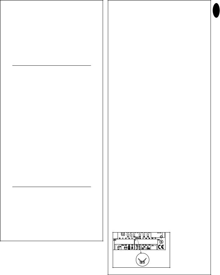
ANSCHLUSSÜBERSICHT
Motoren: Schließen Sie die Steuerung genau nach der Anschlussübersicht an. Der Torflügel der als Erster öffnen soll ist Motor 1 (M1) und muss in seiner ersten Fahrt das Tor ÖFFNEN. Schliesst er müssen die Anschlüsse 6 mit 8 oder bei Motor2 (M2) 9 mit 11 getauscht werden.
Zwischen die Kabel 6 und 8 bzw. 9 und 11 muss der mitgelieferte Kondensator montiert werden. (Der Kondensator kann aus Platzgründen auch in einer Verteilerdose untergebracht werden. Stellen Sie sicher, dass er richtig angeklemmt ist und eine gute elektrische Verbindung hat. Der Kondensator ist verantwortlich für die Kraft, die der Motor später besitzt.
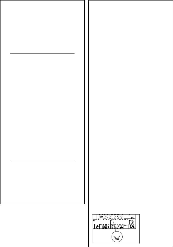
ANSCHLUSSÜBERSICHT |
|
||
Beschreibung der Klemmenbelegung |
|
||
|
|||
|
|
|
|
|
Anschluss der Zuleitung: |
|
D-1 |
Klemme 1 |
N (blau) |
|
|
Klemme 2 |
PE (grün-gelb) |
|
|
Klemme 3 |
L1 - 230 V (schwarz) |
|
|
|
|||
|
Anschluss der Blinkleuchte: |
|
|
Klemme 4 |
L |
|
|
Klemme 5 |
L (230V) |
|
|
|
Anschlüsse der Motoren: |
|
|
|
|
|
|
|
Erster Motor (M1): |
|
|
Klemme 6 |
M1 Fahrtrichtung AUF (braun-schwarz) |
|
|
|
(+ Kondensator) |
|
|
Klemme 7 |
N (blau) |
|
|
Klemme 8 |
M1 Fahrtrichtung ZU (schwarz-braun) |
|
|
|
(+ Kondensator) |
|
|
|
|
|
|
|
Zweiter Motor (M2): |
|
|
Klemme 9 |
M2 Fahrtrichtung AUF (schwarz-braun) |
|
|
|
(+ Kondensator) |
|
|
Klemme 10 |
N (blau) |
|
|
Klemme 11 |
M2 Fahrtrichtung ZU (braun-schwarz) |
|
|
|
(+ Kondensator) |
|
|
|
Infrarot-Lichtschranke |
|
|
Klemme 12 |
Photozelle (NC) Aktiv in Schliessen |
|
|
Klemme 13 |
COM |
|
|
Klemme 14 |
Photozelle (NC) Aktiv in Öffnen |
|
|
|
(Ohne Lichtschranke - Brücke zwischen 12, 13 |
|
|
|
und14!) |
|
|
|
Beschreibung der Klemmenbelegung |
|
|
|
NOTSTOP-FUNKTION |
|
|
Klemme 15 |
COM |
|
|
Klemme 16 |
Stop (NC) ohne Notstopschalter Brücke |
|
|
|
zwischen 15 und 16 |
|
|
|
Anschluss der Steuerleitungen: |
|
|
|
|
|
|
Klemme 17 |
Taster extern (NO) Motor 1 (Fußgänger-Funktion) |
|
|
Klemme 15 |
COM |
|
|
Klemme 18 |
Taster extern (NO) Motor 1 + 2 |
|
|
|
Anschluss für Elektroschloss: |
|
|
Klemme 19 |
Versorgungsspannung 12 V AC |
|
|
Klemme 20 |
Versorgungsspannung 12 V AC |
|
|
|
|
|
|
|
Anschluss für Zusatzgeräte & Lichtschranke: |
|
|
|
|
|
|
Klemme 21 |
Versorgungsspannung 24 V AC (500 mA max.) |
|
|
Klemme 22 |
Versorgungsspannung 24 V AC |
|
|
|
|
|
|
BESCHREIBUNG DER JUMPER
JP1: MOTOR
OPEN: (ohne Jumper): Nur für einflügelige Tor (nur Motor 1 Bedienung)
CLOSED: (mit Jumper): Nur für zweiflügelige Tore (Motor 1 und 2 Bedienung)
JP2: Kanal 2 Funkempfänger
Werden beide Lernkanäle zusammengelegt (A-Seite), verdoppelt sich die Speicherkapazität des Funkempfängers. Das Tor lässt sich dann nur komplett öffnen. Die Funktion “Fussgänger” entfällt.
A-Seite (optional): Empfängerkanal 2 wird Empfängerkanal 1 zusammengeschlossen
B-Seite (Standard): Die beiden Kanäle des Funkempfängers arbeiten getrennt voneinander.
A JP2 B |
709236B-D - 05.2004

SICHERHEIT
BLINKLEUCHTE (OPTIONAL)
Die Verwendung der Blinkleuchte ist vorgeschrieben. Sie dient der Sicherheit und warnt Personen im Umfeld des Tores, daß sich das Tor bewegt. Mittels Schrauben und Dübeln wird die Blinkleuchte befestigt. Das Erdungskabel muß bis zur Lampe geführt werden. Die Montage erfolgt üblicherweise auf dem höchsten Punkt (Pfeiler). Kabelquerschnitt: 0,75mm2, 3-polig
Spannung: 230Volt /AC.
LICHTSCHRANKE (OPTIONAL)
Die Lichtschranke dient der Absicherung des Tores und muss verwendet werden. Der Montageort ist abhängig von der Bauweise des Tores. Üblicherweise wird die Lichtschranke ungefähr in Kniehöhe montiert, ca. 35cm vom Boden. Die Lichtschranken bestehen aus einem Sender und einem Empfängerteil und müssen einander gegenüber liegen. Mit einem Schraubenzieher läßt sich das Lichtschrankengehäuse (Plastik) öffnen. Die Lichtschranke wird mittels kleinen Schrauben und Dübeln an der Wand befestigt. Die Verwendung einer einzigen Lichtschranke ist Mindestvoraussetzung, wir empfehlen die Verwendung einer zweiten Lichtschranke (gglfs. noch weitere Absicherungen).
Es gibt die Möglichkeit die Lichtschranke wie folgt anzuschließen. Aktiv in "ÖFFNEN" (Klemme 14) oder Aktiv in "Schließen" (Klemme 12). Die Anleitung beschreibt den Anschluß einer einzigen Lichtschranke und benutzt damit beide Sicherheitseingänge d.h. Aktiv in beiden Richtungen. Der Dipschalter 4 auf der Steuerung steuert die Reaktion der Torflügel bei unterbrechen der Lichtschranke während des Schließen des Tores. Aktive Lichtschranke stoppt (nur) das Tor oder Aktive Lichtschranke reversiert das Tor in Richtung auf.
Das Sendeteil benötigt ein 2-poliges Kabel, das Empfängerteil ein 4 poliges. Kabelquerschnitt: 0,5mm2 oder größer. Spannung: 12/24Volt AC/DC. Klemmen (12-13-14) (22/23).
NOTSTOP (OPTIONAL)
Wird ein Schalter angeschlossen kann mit damit die Anlage gestoppt oder gesperrt werden. Eine Bewegung der Flügel wird sofort unterbrochen. Der Kontakt kann auch je nach Grad des Sicherheitsbedarfes am Tor mit den Kontakten der Lichtschranke verbunden werden. Damit wird jede Flügelbewegung sofort gestoppt.
TOTMANNBETRIEB
Im Totmannbetrieb darf ein Tor ohne Sicherheitseinrichtungen betrieben werden, insofern es komplett eingesehen werden kann. Im oberen Bereich der Steuerung befinden sich 3 Dip-Schalter. Stellen Sie den Dip-Schalter 2 auf Position ON. Die Steuerung funktioniert nur noch, wenn mittels Handsender, Schlüsselschalter oder Taster kontinuierlich Signal gegeben wird. Bei Unterbrechung bleibt das Tor stehen und bewegt sich beim nächsten Signal in die entgegengesetzte Fahrtrichtung.
STEUERLEITUNGEN
Es ist damit möglich, nur ein Tor zu öffnen oder beide Tore. Diese Funktion ist auch mit der Funkfernbedienung möglich. Siehe Einlernen der Fernbedienung. Der Test-Taster auf der Steuerung aktiviert immer beide Motoren.
Bei überlappenden Flügeln ist die Einstellung der Flügelverzögerung notwendig. Nicht überlappende Flügel dürfen nicht gleichzeitig schließen. Einklemmgefahr (siehe Beschreibung: Potentiometer).
SCHLÜSSELSCHALTER INSTALLATION
Anschluß der Kabel laut Schaltplan.
ELEKTRO SCHLOSS (OPTIONAL)
Ein Elektro-Schloss kann an die Anschlüsse 19 - 20 angeschlossen werden. Ausgangsspannung: 12 V AC.
Siehe auch Einstellung der Dipschalter!
BESCHREIBUNG DER DIPSCHALTER
Die Dipschalter steuern generelle Funktionen der Anlage:
•Automatisch Schließen oder Standard
•Totmann
•Elektroschloss Funktion
•Reaktion der Lichtschranke
Dipschalter 1 |
ON |
Automatisches Schließen |
|
OFF |
Standard |
Dipschalter 2 |
ON |
Totmann |
|
OFF |
Standard |
Dipschalter 3 |
ON |
E-Schloss Funktion |
|
OFF |
Standard |
Dipschalter 4 |
ON |
Lichtschranke (für Schliessen) |
|
|
stoppt Tor |
|
OFF |
Standard Lichtschranke (für |
|
|
Schließen) öffnet Tor. |
BESCHREIBUNG DER POTENTIOMETER
• Force M1 Force M2:
Regeln die Kraft mit der der Flügel arbeitet, für jeden Flügel getrennt. Mit den Dreh Potentiometern wird die Feineinstellung für das Tor vorgenommen.
Ist die Kraft des sich bewegenden Flügels an der Schliesskante grösser als 400N müssen zusätzliche Sicherheitseinrichtungen (Lichtschranken, Kontaktleisten) montiert werden. Sicherheitseinrichtungen müssen den Normen entsprechen (Europa: EN60335-1). Siehe auch Sicherheitsregeln.
• PAUSE
Diese Funktion ist nur aktiv wenn der Dipschalter 1 auf ON steht. Sie regelt die Zeit die das Tor offen gehalten wird, bevor es sich wieder schließt. Einstellbar: 8-200 Sekunden.
• OPEN-CLOSED
Regelt die maximale Laufzeit der Flügel. Stellen Sie die Laufzeit auf ca. 30% und testen Sie dann. Die richtige Einstellung ist dann erreicht, wenn in einem kompletten Zyklus der Antrieb jeweils 3-5 Sekunden am Anschlag weiter läuft(brummt). Das ist notwendig weil die benötigte Laufzeit sich durch äußere Einflüsse ändert und ein sicheres erreichen der Endposition gewährleistet sein soll (Wind, Temperatur, Bodenveränderungen). Aus diesem Grund sind Anschläge in ZU und AUF zwingend vorgeschrieben.
Einstellbar: 7-60 Sekunden
• WING DELAY
Steuert die Flügelverzögerung bei sich überlappenden Flügeln. Der Flügel M1 wird zuerst geöffnet und als letztes geschlossen. Damit niemand zwischen zwei sich schliessenden Flügeln eingeklemmt werden kann ist es notwendig, dass immer eine Verzögerung eingestellt wird.
Einstellbar: 0-35 Sekunden.
D-2
709236B-D - 05.2004
BESCHREIBUNG DER LEDS
LED 1 |
rot |
Überwacht die Lichtschranke für Tor Schließen. |
|
|
LED AN = OK |
LED 2 |
rot |
Überwacht die Lichtschranke für Tor Öffnen LED |
|
|
AN = OK |
LED 3 |
gelb |
Überwacht den Notstop Kontakt. AN=OK |
LED 4 |
grün |
Zeigt Signale von Schlüsselschaltern, Tastern |
|
|
oder Funk an. Funktion Tor einflügelig öffnen |
|
|
AN= Signal liegt an. |
LED 5 |
grün |
Zeigt Signale von Schlüsselschaltern, Tastern |
|
|
oder Funk an. Funktion beide Flügel öffnen AN= |
|
|
Signal liegt an. |
LED 6 |
rot |
Blinkt langsam = OK |
|
|
Blinkt schnell = Überprüfen Sie alle Anschlüsse |
|
|
zu den Motoren, Kondensator, Blinkleuchte und |
|
|
beseitigen Sie jede Feuchtigkeit an |
|
|
Verbindungsklemmen. |
BESCHREIBUNG DER SICHERUNGEN
F1 5.0A Hauptsicherung: Sichert die die komplette Steuerung und schützt die Motoren. Niemals durch eine stärkere Sicherung ersetzen.
F2 |
0,5A |
Nebensicherung für 24Volt Ausgang. |
F3 |
2,0A |
Nebensicherung E-Schloss 12Volt Ausgang. Bitte |
|
|
beachten Sie den Strombedarf des von Ihnen |
|
|
verwendeten E-Schlosses. |
F4 |
0,315A |
Nebensicherung Logik: Taster, Notstop, |
|
|
Lichtschranke, Empfänger |
EINLERNEN DER FERNBEDIENUNG
Es können 15 Handsender auf jeden Lernkanal angelernt werden. Bei größeren Anlagen empfiehlt sich schon aus organisatorischen Gründen ein externer Empfänger oder die Verwendung eines Schlüsselschalters oder eines Codeschlosses, die in der Einfahrt angebracht werden.
Der Funkempfänger ist seitlich gesteckt und darauf befinden sich die beiden kleinen Lerntasten.
Die postzugelassene, gebührenfreie Funkfernsteuerung arbeitet mit einem per Computer vorprogrammierten privaten Sicherheitscode.
Damit kann Ihr Torantrieb nur mit einem entsprechend gleich codierten Handsender aktiviert werden. Die Reichweite ist von örtlichen Begebenheiten abhängig.
Das Empfängerteil der Motorsteuerung hat eine integrierte Selbstlernfunktion. Sie kann auf den vorprogrammierten Code des Handsenders durch Drücken der Lerntaste eingestellt werden. Die Steuerung besitzt zwei Lernkanäle. Sie kann damit durch
entsprechendes Betätigen des Handsenders ein Tor oder beide Tore gleichzeitig öffnen oder schließen. Erhält beispielsweise Kanal 1 (2) den Fernbedienungscode des Handsenders, wird nur ein Flügel geöffnet. Lernen Sie den Kanal 2 (1) der Fernbedienung an, können Sie mit dieser Taste beide Flügel betätigen. Um den Code einzuspeichern, drücken Sie die von Ihnen gewählte Taste des Handsenders und halten diese fest. Drücken Sie mit der anderen Hand kurz die Lerntaste der Elektronik. Wiederholen Sie den Vorgang für alle Handsender.
LÖSCHEN PROGRAMMIERTER FERNBEDIENUNGSCODE
Drücken Sie die jeweilige Lerntaste (1 oder 2) ca. 10 Sekunden auf der Empfängerplatine bis die Lern-LED erlischt. Die zu dieser Lerntaste gehörenden “erlernten” Codierungen sind dann gelöscht.
NEUPROGRAMMIEREN
Zum Neuprogrammieren sind die genannten Schritte für die Codierung für alle in Betrieb befindlichen Fernbedienungen bzw. ihrer Bedienungstasten zu wiederholen.
Die Reichweite der Funkfernsteuerung ist von den örtlichen Gegebenheiten abhängig. Halten Sie die Taste am Handsender solange gedrückt (ca. 2 Sekunden), bis eine Bewegung des Tores erkennbar ist.
Ihre Funkfernsteuerung ist digitalcodiert, d.h. eine unbeabsichtigte Betätigung des Torantriebes kann nahezu ausgeschlossen werden.
INBETRIEBNAHME
Gehen Sie behutsam und in Ruhe vor. Nehmen Sie sich für die Grundeinstellung viel Zeit. Der Zeitbedarf für die erste Einstellung kann bis zu 30Minuten sein. Evtl. sollte eine zweite Person helfen damit Veränderungen an der Steuerung einfacher erfolgen (Strom AUS bzw. EIN) können.
1.Schließen Sie die Steuerung inklusive der Sicherheitseingänge an.
2.Überprüfen Sie die LED’s.
3.Bringen Sie das Tor in eine halb offene Position und verriegeln Sie es, drücken Sie anschließend den Test-Taster. Beide Flügel müssen sich nun öffnen. Schließt ein Flügel anstatt zu öffnen ist dieser Motor verkehrt angeschlossen und die Motorkabel für diesen betreffenden Motor müssen vertauscht werden (siehe Anschluß). Es werden die Kabel getauscht in die auch der Kondensator eingeklemmt ist. Sie bestimmen die Laufrichtung der Motoren. Wiederholen Sie anschließend den kompletten Vorgang bis beide Flügel in der ersten Bewegung öffnen. Achtung, schalten sie dazu immer den Strom aus.
4.Öffnen beide Flügel nun in der ersten Bewegung nach Anschluß der Steuerung gehen Sie wie folgt vor.
5.Unterbrechen Sie die Stromzufuhr zur Steuerung und schließen Sie sie nach einigen Sekunden wieder an. Schließen Sie beide Torflügel manuell und verriegeln Sie beide Flügel.
6.Stellen Sie alle Potentiometer auf 30% und stellen Sie sicher, daß der Dipschalter 1 auf OFF (unten) ist.
7.Starten Sie nun mit dem Test-Taster die Steuerung und beobachten Sie den Ablauf. Schließen Sie das Tor wieder per Test-Taster OHNE dass Sie eine Einstellung vorgenommen haben. Schließt das Tor von alleine nicht komplett, entriegeln Sie den Antrieb und schließen es manuell nach abschalten der Steuerung.
8.Stellen Sie nun die Potentiometer auf andere (höhere) Werte ein, angepaßt an den Erfahrungswert aus dem Versuch. (z.B. Laufzeit erhöhen, Kraft korrigieren. Flügelverzögerung) Starten Sie jetzt einen zweiten Versuch und gehen Sie wieder wie vorhin vor und schließen Sie das Tor zuerst mit dem Test-Taster bevor Sie wieder Einstellungen vornehmen.
9.Sind alle Einstellungen getroffen worden, überprüfen Sie die Funktion der Lichtschranken, Taster, Blinkleuchte, Handsender, Zubehör etc. Sollten sie Automatisch Schließen wünschen, ändern Sie nun die Dipschalter Einstellung und regeln Sie das Potentiometer für die Pause ein.
10.Zeigen Sie allen Personen, die Umgang mit dem Tor haben, wie die Bewegungen der Tores ablaufen, wie die Sicherheitsfunktionen arbeiten und wie der Antrieb von Hand betätigt werden kann.
E G - K o n f o r m i t ä t s e r k l ä r u n g
Die Steuerung für....................................................................................... |
CB1 |
erfüllen alle Bedingungen der |
|
Richtlinien............................................... |
EN300220-3, EN55014, EN61000-3, |
............................................................ |
ETS 300 683, EN60555, & EN60335-1 |
sowie die Zusätze ..................................................... |
73/23/EEC, 89/336/EEC |
I n t e g r a t i o n s e r k l ä r u n g
Die Steuerung für CB1 erfüllen, wenn sie in Verbindung mit einem Tor gemäß Herstelleranweisungen installiert und instandgehalten werden, alle Bedingungen der EU-Richtlinie 89/392/EEC und deren Zusätze.
Ich, der Unterzeichner, erkläre hiermit, daß das vorstehend genannte Gerät und das in der Montageanleitung aufgeführte Zubehör, die vorstehenden Vorschriften und Richtlinien erfüllt.
THE CHAMBERLAIN GROUP, INC.
Elmhurst, IL 60126
USA
Barbara P. Kelkhoff
June, 2003
Manager, Reg. Affairs
D-3
709236B-D - 05.2004 |
© Chamberlain GmbH, 2004 |
Gedruckt in der EU |

COMMANDE
Le raccordement de la commande doit s'effectuer en dernier, c'est-à- dire après avoir monté les moteurs, posé les câbles nécessaires et fixé les barrières photoélectriques ou les barres palpeuses. En cas de montage fixe, il faut prévoir un dispositif de coupure de l'alimentation secteur présentant un intervalle minimal de contact de 3 mm (interrupteur général).
Explications : dans la présente notice, les contacts de relais sont appelés contacts NF (normalement fermé) ou NO (normalement ouvert).
•Les contacts NF sont normalement fermés et permettent d'ouvrir le circuit
•Les contacts NO sont normalement ouverts et permettent de fermer le circuit
L'humidité et la présence d'eau ont un effet destructeur sur la commande. S'assurer qu'il n'y a aucun risque de pénétration d'eau et d'humidité ou de stagnation d'eau dans la commande. Toutes les ouvertures et traversées de câbles doivent impérativement être obturées de manière étanche.
INSTALLATION ELECTRIQUE
Montage du boîtier de la commande : La commande du moteur fait appel à une électronique ultramoderne pilotée par microprocesseur. Elle dispose de toutes les possibilités de raccordement et de toutes les fonctions nécessaires à un fonctionnement en toute sécurité.
Le boîtier de commande avec la commande du moteur doit être monté avec les passages de câbles vers le dessous. Il ne doit pas être exposé de manière prolongée au rayonnement solaire direct. L'électronique permet de régler avec une grande précision la force de traction et de pression. Lorsque le montage/le réglage sont effectués dans les règles de l'art, il doit être possible de retenir le portail à la main.
Durant le fonctionnement, il est à tout moment possible de stopper le portail par le biais de la télécommande, par actionnement d'une touche ou par le biais de l'interrupteur à clé.
Le battant du portail doit disposer d'une butée solide pour les positions "OUVERT" et "FERME", car les ouvre-portails ne disposent pas de fins de course.
Distribution du courant : Le câble venant du bras d'entraînement doit être posé dans une boîte de dérivation étanche disponible dans le commerce. Il est possible de prévoir un câblage fixe depuis la boîte de dérivation jusqu'à la commande. Dans bien des cas, il est possible de faire passer directement dans la boîte le câble d'un entraînement fixé juste à côté de la commande. Ne jamais enterrer des boîtes de dérivation.
Il convient de ne pas utiliser de câbles de section inférieure à celles indiquées ci-après :
100-230 volts 1,5mm2 ou plus
0-24 volts 0,5mm2 ou plus
Conseils : Les fils de sonnette posent souvent des problèmes dans la pratique, car ils occasionnent une perte de tension importante sur les grandes longueurs de câble. Répartir les câbles dans des goulottes séparées pour le moteur et pour la barrière photoélectrique, notamment lorsque l'installation comporte des interrupteurs à clé, des poussoirs de démarrage (provenant de la maison), sous peine de dérangements en cas de grandes longueurs de câble.
VUE D'ENSEMBLE DES RACCORDEMENTS
Moteurs : Raccorder la commande exactement comme indiqué dans la vue d'ensemble des raccordements. Le battant qui doit s'ouvrir en premier correspond au moteur 1 (M1) et doit OUVRIR le portail lors de son premier déplacement. Dans le cas contraire, il faut permuter les connexions 6 et 8 (moteur M1) ou 9 et 11 (moteur M2).
Le condensateur fourni doit se monter entre les câbles 6 et 8 et 9 et 11. (Pour des raisons d'encombrement, le condensateur peut également être monté dans une boîte de dérivation). S'assurer que la polarité des branchements du condensateur est correcte et qu'il présente une bonne liaison électrique. Le condensateur est responsable de la force que le moteur développera ultérieurement.
709236B-F - 05.2004
VUE D'ENSEMBLE DES RACCORDEMENTS |
|
|||
Description de l'affectation des bornes |
|
|||
|
||||
|
|
|
|
|
|
|
Raccordement du câble d'alimentation |
|
F-1 |
|
|
|
|
|
Borne |
1 |
N (bleu) |
|
|
|
|
|||
Borne |
2 |
PE (vert-jaune) |
|
|
Borne |
3 |
L1 - 230V (noir) |
|
|
|
||||
|
|
Raccordement de la lampe clignotante |
|
|
Borne |
4 |
L |
|
|
Borne |
5 |
L (230V) |
|
|
|
|
Raccordement des moteurs |
|
|
|
|
Premier moteur (M1): |
|
|
Borne 6 |
M1 Sens de fonctionnement OUVERT |
|
|
|
|
|
(marron-noir) (+ condensateur) |
|
|
Borne |
7 |
N (bleu) |
|
|
Borne 8 |
M1 Sens de fonctionnement FERME |
|
|
|
|
|
(noir-marron) (+ condensateur) |
|
|
|
|
|
|
|
|
|
Deuxième moteur (M2): |
|
|
Borne |
9 |
M2 Sens de fonctionnement OUVERT (noir-marron) |
|
|
|
|
(+ condensateur) |
|
|
Borne |
10 |
N (bleu) |
|
|
Borne |
11 |
M2 Sens de fonctionnement FERME |
|
|
|
|
(marron-noir) (+ condensateur) |
|
|
|
|
Barrière photoélectrique à infrarouge |
|
|
Borne |
12 |
Cellule photoélectrique (NF) active à la fermeture |
|
|
Borne 13 |
COM |
|
|
|
Borne |
14 |
Cellule photoélectrique (NF) active à l'ouverture |
|
|
|
|
(sans barrière photoélectrique – cavalier entre 12, |
|
|
|
|
13 et 14 !) |
|
|
|
|
Description de l'affectation des bornes |
|
|
|
|
FONCTION D'ARRET D'URGENCE |
|
|
Borne 15 |
COM |
|
|
|
Borne |
16 |
Stop (NF) sans interrupteur d'arrêt d'urgence, |
|
|
|
|
cavalier entre 15 et 16 |
|
|
|
|
Raccordement des câbles de commande |
|
|
Borne |
17 |
Touche externe (NO) Moteur 1 (fonction piéton) |
|
|
Borne 15 |
COM |
|
|
|
Borne |
18 |
Touche externe (NO) Moteurs 1 + 2 |
|
|
|
|
|
|
|
|
|
Raccordement de la serrure électrique |
|
|
|
|
|
|
|
Borne |
19 |
Tension d'alimentation 12 V CA |
|
|
Borne |
20 |
Tension d'alimentation 12 V CA |
|
|
|
|
Raccordement pour appareils supplémentaires & |
|
|
|
|
barrière photoélectrique |
|
|
Borne |
21 |
Tension d'alimentation 24 V CA (500 mA max.) |
|
|
Borne |
22 |
Tension d'alimentation 24 V CA |
|
|
|
|
|
|
|
DESCRIPTION DES CAVALIERS
JP1 : MOTEUR
OPEN : (sans cavalier) : uniquement pour portails à un seul battant (commande uniquement avec moteur 1).
CLOSED : (avec cavalier) : uniquement pour portails à deux battants (commande moteurs 1 et 2).
JP2 : récepteur radio canal 2.
Lorsque les deux canaux d'apprentissage sont regroupés (côté A), la capacité mémoire du récepteur radio est multipliée par deux. Seule l'ouverture complète de la porte est alors possible. La fonction "piéton" est supprimée.
Côté A : (option) Le canal de réception 2 est regroupé avec le canal de réception 1.
Côté B : (standard) Les deux canaux du récepteur radio fonctionnement séparément.
A JP2 B |
SECURITE
LAMPE CLIGNOTANTE (OPTION)
L’utilisation de la lampe clignotante est obligatoire. Elle sert à la sécurité et prévient les personnes qui se trouvent à proximité du portail que ce dernier est en mouvement. La lampe clignotante se fixe au moyen de vis et de chevilles. Le câble de mise à la terre doit être tiré jusqu’à la lampe. Le montage s’effectue habituellement au point le plus haut (pilier). Section du câble : 0,75 mm2, tripolaire, tension : 230 V CA.
BARRIERE PHOTOELECTRIQUE (OPTION)
La barrière photoélectrique sert à la protection du portail et doit être utilisée. Son emplacement de montage dépend de la construction du portail. Elle se monte généralement à hauteur des genoux, à environ 35 cm du sol. Les barrières photoélectriques se composent d’un émetteur et d’un récepteur qui doivent être disposés l’un en face de l’autre. Le boîtier (en plastique) de la barrière lumineuse peut s’ouvrir à l’aide d’un tournevis. La barrière photoélectrique se fixe au mur au moyen de petites vis et de chevilles. L’utilisation d’une seule barrière photoélectrique représente la configuration minimale requise, mais nous recommandons d’en utiliser une deuxième (ainsi que d’autres protections supplémentaires, le cas échéant). La barrière photoélectrique peut être raccordée comme suit : active pour "OUVRIR" (borne 14) ou active pour "FERMER" (borne 12). Les présentes instructions décrivent le raccordement d'une seule barrière photoélectrique, en utilisant donc les deux entrées de sécurité, c'est-à-dire barrière active dans les deux sens. Le commutateur DIP (à positions multiples) 4 sur la commande pilote la réaction des battants en cas d'interruption de la barrière photoélectrique durant la fermeture du portail. Lorsqu'elle est active, la barrière photoélectrique se contente de stopper le portail ou peut provoquer
l'inversion du sens de fonctionnement du portail. L'émetteur nécessite un câble bipolaire et le récepteur un câble quadripolaire. Section : 0,5 mm 2 ou plus.
Tension : 12/24 volts CA/CC. Bornes (12-13-14) (22/23).
ARRET D'URGENCE (OPTION)
Lorsqu'un interrupteur est raccordé, il est alors possible de l'utiliser pour stopper ou verrouiller l'installation. Tout mouvement des battants est immédiatement interrompu. Selon le degré de sécurité requis, ce contact peut également être relié aux contacts de la barrière photoélectrique, ce qui a pour effet de stopper immédiatement tout mouvement des battants.
HOMME MORT
En mode "homme mort", il est possible de faire fonctionner un portail sans dispositif de sécurité, sous réserve que l'ensemble du portail soit visible. Sur la partie supérieure de la commande se trouvent 3 commutateurs DIP. Régler le commutateur DIP 2 sur la position ON. La commande ne fonctionne alors que lorsqu'elle reçoit un signal continu provenant de la télécommande, de l'interrupteur à clé ou de la touche. En cas d'interruption du signal, le portail s'arrête et se déplace en sens inverse dès réception du signal suivant.
CABLES DE COMMANDE
Il est possible d'ouvrir seulement un battant ou les deux. Cette fonction est également réalisable à l'aide de la télécommande. Voir "Apprentissage de la télécommande". La touche de test sur la commande active systématiquement les deux moteurs. En cas de battants à recouvrement, il est nécessaire de régler la temporisation. Les battants sans recouvrement ne doivent pas se fermer en même temps. Risque de coincement (voir description : potentiomètres).
INSTALLATION DE L'INTERRUPTEUR A CLE
Raccordement des câbles : voir schéma électrique.
SERRURE ELECTRIQUE (OPTION)
Il est possible de raccorder une serrure électrique aux bornes 19 – 20. Tension de sortie : 12 V CA.
Voir également le réglage des commutateurs DIP !
DESCRIPTION DES COMMUTATEURS DIP
Les commutateurs DIP pilotent les fonctions générales de l'installation :
•Fermeture automatique ou standard
•Homme mort
•Fonctionnement de la serrure électrique
•Réaction de la barrière photoélectrique
Commutateur DIP 1 |
ON |
Fermeture automatique |
|
OFF |
Standard |
Commutateur DIP 2 |
ON |
Homme mort |
|
OFF |
Standard |
Commutateur DIP 3 |
ON |
Fonctionnement de la serrure |
|
|
électrique |
|
OFF |
Standard |
Commutateur DIP 4 |
ON |
La barrière photoélectrique (pour |
|
|
Fermer) stoppe le portail |
|
OFF |
Standard. La barrière |
|
|
photoélectrique (pour Fermer) |
|
|
ouvre le portail. |
DESCRIPTION DES POTENTIOMETRES
• Force M1 Force M2:
Ils permettent de régler séparément la force de fonctionnement de chaque battant. Le potentiomètre rotatif permet un ajustage précis pour le portail. Si la force mesurée au niveau de l'arête du battant en mouvement est supérieure à 400 N, il faut monter des dispositifs de sécurité supplémentaires (barrières photoélectriques, barres palpeuses) conformes aux normes en vigueur (en Europe : EN 60335-1). Se reporter également aux consignes de sécurité.
• PAUSE
Cette fonction est uniquement active lorsque le commutateur DIP 1 est sur ON. Elle permet de régler le temps pendant lequel le portail reste ouvert avant de se refermer. Plage de réglage : 8-200 secondes.
• OPEN-CLOSED
Ce potentiomètre permet de régler la durée de fonctionnement des battants. Régler cette valeur à environ 30 % et faire un essai. Le bon réglage est atteint lorsque, dans un cycle complet, l'entraînement continue à tourner (ronflement) pendant environ 3 à 5 secondes une fois arrivé en butée. Ce réglage est nécessaire dans la mesure où la durée de fonctionnement varie sous l'effet de facteurs externes (vent, température, variations de niveau du sol) et où il faut garantir que le portail atteindra bien sa position finale. De ce fait, il est impératif de monter des butées en position FERME et OUVERT. Plage de réglage
:7–60 secondes.
•WING DELAY
Ce potentiomètre permet de régler la temporisation en cas de battants à recouvrement. Le battant M1 s'ouvre en premier et se ferme en dernier. Afin que personne ne risque d'être coincé entre les battants en cours de fermeture, il faut systématiquement régler une temporisation.
Plage de réglage : 0–35 secondes.
DESCRIPTION DES DEL
DEL 1 |
rouge |
Surveille la barrière photoélectrique pour "fermer |
|
|
portail". ALLUMEE = OK |
DEL 2 |
rouge |
Surveille la barrière photoélectrique pour "ouvrir |
|
|
portail". ALLUMEE = OK |
DEL 3 |
jaune |
Surveille le contact d'arrêt d'urgence. ALLUMEE |
|
|
= OK |
DEL 4 |
verte |
Indique la présence de signaux d'interrupteurs à |
|
|
clé, touches ou télécommandes. Fonction "ouvrir |
|
|
un battant du portail". ALLUMEE = signal |
|
|
appliqué |
DEL 5 |
verte |
Indique la présence de signaux d'interrupteurs à |
|
|
clé, touches ou télécommandes. Fonction "ouvrir |
|
|
les deux battants". ALLUMEE = signal appliqué |
DEL 6 |
rouge |
Clignotement lent = OK |
|
|
Clignotement rapide = vérifier tous les |
|
|
branchements vers les moteurs, le |
|
|
condensateur, la lampe clignotante et éliminer |
|
|
toute trace d'humidité au niveau des bornes de |
|
|
raccordement. |
F-2
709236B-F - 05.2004
DESCRIPTION DES FUSIBLES
F1 |
5.0A |
Fusible principal : protège l'ensemble de la |
|
|
commande et les moteurs. Ne jamais le remplacer |
|
|
par un fusible de plus fort calibre. |
F2 |
0,5A |
Fusible auxiliaire pour la sortie 24 volts. |
F3 |
2,0A |
Fusible auxiliaire pour la sortie 12 volts de la serrure |
|
|
électrique. Tenir compte de la consommation de la |
|
|
serrure électrique utilisée. |
F4 |
0,315A |
Fusible auxiliaire pour la logique : touches, arrêt |
|
|
d'urgence, barrière photoélectrique, récepteur |
APPRENTISSAGE DE LA TELECOMMANDE
Il est possible de programmer 15 télécommandes sur chaque canal d'apprentissage. Dans le cas d'installations plus importantes, il est recommandé – ne serait-ce que pour des raisons d'organisation – de prévoir un récepteur externe ou d'utiliser un interrupteur à clé ou une serrure à code au niveau de l'accès. Sur le récepteur radio enfiché sur le côté se trouvent les deux petites touches d'apprentissage. La télécommande, exonérée de redevances et homologuée par les services techniques, fonctionne avec un code de sécurité privé préprogrammé par ordinateur. Votre ouvre-portail ne peut donc être activé que par une télécommande présentant le même code. La portée dépend des conditions locales. Le récepteur de la commande du
moteur dispose d'une fonction d'auto-apprentissage intégrée. Il se règle sur le code pré-programmé de la télécommande par actionnement de
la touche d'apprentissage. La commande comporte deux canaux d'apprentissage. Elle peut ainsi, par actionnement correspondant de la télécommande, ouvrir ou fermer un battant ou les deux battants en même temps. Par exemple, si le canal 1 (2) reçoit le code de commande à distance de la télécommande, l'ouverture ne concernera qu'un seul battant. Après apprentissage du canal 2(1) de la télécommande, vous pourrez actionner les deux battants à l'aide de cette touche. Pour mémoriser ce code, il suffit d'appuyer sur la touche voulue et de la maintenir enfoncée. Pendant ce temps, avec l'autre main, appuyer brièvement sur la touche d'apprentissage de l'électronique.Répéter cette opération pour toutes les télécommandes.
EFFACEMENT DE CODES DE COMMANDE A DISTANCE DEJA PROGRAMMES
Appuyer sur la touche d'apprentissage correspondante(1 ou 2) sur la platine du récepteur pendant env. 10 secondes jusqu'à ce que la DEL d'apprentissage s'éteigne. Les codes "appris" correspondant à cette touche d'apprentissage sont alors effacés.
NOUVELLE PROGRAMMATION
Pour reprogrammer le système, répéter les étapes de codage pour toutes les télécommandes en service ou pour vos touches de commande. La portée de la commande radio à distance dépend des conditions locales. Maintenir enfoncée la touche de la télécommande (pendant env. 2 secondes) jusqu'à observer un déplacement du portail. Le principe de codage numérique de la commande radio à distance permet d'exclure pratiquement tout risque d'actionnement involontaire de l'ouvre-portail.
MISE EN SERVICE |
|
|
Travailler au calme et sans précipitation. Prenez tout votre temps |
|
|
|
||
pour effectuer le réglage de base. Cette opération peut prendre |
F-3 |
|
jusqu'à 30 minutes. Vous pouvez éventuellement demander à une |
||
|
||
autre personne de vous aider (p. ex. pour COUPER ou RETABLIR le |
|
|
courant) afin de faciliter les modifications nécessaires sur la |
|
|
commande. |
|
1.Raccorder la commande ainsi que les entrées de sécurité.
2.Contrôler les DEL.
3.Amener le portail en position mi-ouverte et le verrouiller, appuyer ensuite sur la touche de test. Les deux battants doivent alors
s'ouvrir. Si l'un des battants se ferme au lieu de s'ouvrir, son moteur est branché à l'envers et les câbles correspondants doivent donc
être permutés (voir raccordement). Il faut permuter les câbles entre lesquels le condensateur est raccordé. Ils déterminent le sens de marche des moteurs. Répéter ensuite l'opération complète jusqu'à ce que les deux battants s'ouvrent dès le premier déplacement du portail. Attention : couper impérativement la tension secteur avant de permuter les câbles.
4.Une fois que les deux battants s'ouvrent dès le déplacement initial du portail après le raccordement de la commande, procéder comme suit :
5.Couper l'alimentation électrique de la commande et la rétablir au bout de quelques secondes. Fermer manuellement les deux battants et les verrouiller.
6.Régler tous les potentiomètres à 30 % et s'assurer que le commutateur DIP 1 est sur OFF (en bas).
7.Démarrer maintenant la commande à l'aide de la touche de test et observer le fonctionnement. Refermer le portail par le biais de la touche de test SANS avoir procédé au moindre réglage. Si le portail ne se ferme pas complètement de lui-même, déverrouiller l'entraînement et refermer le portail manuellement après avoir désactivé la commande.
8.Régler maintenant les potentiomètres sur d'autres valeurs (plus élevées) en fonction des observations effectuées lors de l'essai (p. ex. augmenter la durée de fonctionnement, rectifier la force, régler une temporisation des battants). Refaire un deuxième essai et procéder comme décrit précédemment. Refermer le portail tout d'abord par le biais de la touche de test avant de procéder à de nouveaux réglages.
9.Une fois que tous les réglages sont effectués, contrôler le fonctionnement des barrières photoélectriques, des touches, de la lampe clignotante, des télécommandes, des accessoires, etc. Si vous souhaitez une fermeture automatique, modifier le réglage des commutateurs DIP et régler le potentiomètre sur "Pause".
10.Expliquer à tous les utilisateurs potentiels le mode de fonctionnement du portail, le principe des fonctions de sécurité et la possibilité d'actionnement manuel de l'ouvre-portail.
D é c l a r a t i o n d e c o n f o r m i t é C E
La commande ............................................................................................ |
|
CB1 |
satisfait à toutes les exigences des |
|
|
directives ................................................ |
EN300220-3, EN55014, EN61000-3, |
|
............................................................ |
ETS 300 683, EN60555, & EN60335-1 |
|
ainsi qu'aux dispositions complémentaires................ |
73/23/EEC, 89/336/EEC |
|
D é c l a r a t i o n d ' i n t é g r a t i o n
Lorsqu'elles sont installées en liaison avec un portail et entretenues conformément aux indications du fabricant, les commandes pour CB1 satisfont à toutes les exigences de la directive communautaire 89/392/CEE et de ses dispositions complémentaires.
Je soussigné déclare par la présente que l'appareil précité et les accessoires figurant dans les instructions de montage satisfont aux
prescriptions et directives indiquées ci-dessus.
THE CHAMBERLAIN GROUP, INC. |
|
Elmhurst, IL 60126 |
|
USA |
Barbara P. Kelkhoff |
June, 2003 |
Manager, Reg. Affairs |
709236B-F - 05.2004 |
© Chamberlain GmbH, 2004 |
ELECTRONIC CONTROL
The control board should be the last item to be connected, i.e. mounting the motors, laying the necessary cable and fitting light barriers or contact strips. If installation is to be performed in a permanent location, a means of disconnecting the equipment from the mains supply with a contact clearance of at least 3 mm is needed (master switch).
Please note: in these instructions, relay contacts are designated NC
(normal closed) or NO (normal open).
•NC contacts are closed and open
•NO contacts are open and close
Humidity and water will destroy the control board. Always make sure that water, humidity and condensation cannot enter the control box. It is vitally important that all openings and cable glands are sealed so that they are watertight.
ELECTRICAL INSTALLATION
Installing the electronic control board: the motor control board is a microprocessor-controlled electronic appliance featuring state-of-the- art technology. It is equipped with all the connecting options and functions needed to guarantee safe operation. The control box incorporating the motor control board should be installed with the cable intakes pointing downwards. It should not be continuously exposed to direct sunlight. The electronic equipment enables the pull and push forces to be set with great accuracy. If installed and set correctly, the gate/door can be stopped manually. When in motion, the gate/door can be stopped at any time by operating the remote control, the push-button or the key-operated switch.
The gate/door wing must be fitted with a robust end stop for the 'OPEN' and 'CLOSED' positions as the gate/door drive has no limit switches.
Current distribution: the cable leading from the drive arm must be laid in a standard watertight distribution box. A permanently installed cable can be laid from the distribution box to the control unit. It is often possible to wire the drive, which is fixed beside the control unit directly to the box. Never install distribution boxes underground.
Generally speaking, the following minimum cable crosssectional areas must be adhered to:
100-230Volt |
1.5mm2 |
or more |
0-24Volt |
0.5mm2 |
or more |
Tips: Bell wire is often problematic in practical use because it loses too much voltage if long lengths of wire are used.
Segregate the cables in cable trunking, i.e. motor cable and light barrier cable, especially in the case of key-operated switches and ON switches (from the house wiring system) to prevent interference where long lengths of cable are used.
OVERVIEW OF CONNECTIONS
Motors: connect the control unit exactly in accordance with the overview of connections. The gate/door wing, which opens first, must be motor 1 (M1) and when it first moves it must OPEN the gate/door. If it closes the gate/door, swap terminal 6 with terminal 8 or, in the case of motor 2 (M2), swap terminal 9 with terminal 11.
The capacitor supplied as standard must be installed between cables 6 and 8 and 9 and 11 (for space reasons, the capacitor can also be installed in a distribution box). Make sure that its terminals are properly connected and that there is a good electrical connection. The capacitor determines the force which the motor subsequently develops.
OVERVIEW OF CONNECTIONS
Description of terminal occupancy
|
Mains cable connection: |
Terminal 1 |
N (blue) |
Terminal 2 |
PE (green/yellow) |
Terminal 3 |
L1 - 230 V (black) |
|
Flashing lamp connection: |
Terminal 4 |
L |
Terminal 5 |
L (230V) |
|
Motor connections: |
|
First motor (M1): |
Terminal 6 |
M1 direction of OPEN (brown/black) |
|
(+ capacitor) |
Terminal 7 |
N (blue) |
Terminal 8 |
M1 direction of CLOSED (black/brown) |
|
(+ capacitor) |
|
Second motor (M2): |
Terminal 9 |
M2 direction of OPEN (black/brown) |
|
(+ capacitor) |
Terminal 10 |
N (blue) |
Terminal 11 |
M2 direction of CLOSED (brown/black) |
|
(+ capacitor) |
|
Infrared light barrier |
Terminal 12 |
photocell (NC) active when closing |
Terminal 13 |
COM |
Terminal 14 |
photocell (NC) active when opening |
|
(without light barrier - jumper between 12, 13 & 14!) |
|
Description of terminal occupancy |
|
EMERGENCY STOP FUNCTION |
Terminal 15 |
COM |
Terminal 16 |
Stop (NC) with emergency stop |
|
switch jumper between 15 and 16 |
|
|
|
Control line connection |
Terminal 17 |
External push-button (NO) motor 1 (ped. function) |
Terminal 15 |
COM |
Terminal 18 |
External push-button (NO) motors 1+2 |
|
Electric lock connection |
Terminal 19 |
Distribution voltage 12 V AC |
Terminal 20 |
Distribution voltage 12 V AC |
|
|
|
Connection for additional equipment & light barrier |
Terminal 21 |
Distribution voltage 24 V AC (500 mA max.) |
Terminal 22 |
Distribution voltage 24 V AC |
|
|
DESCRIPTION OF JUMPER
JP1: MOTOR
OPEN: (without jumper): only for single-wing gates (only motor 1 operating).
CLOSED: (with jumper): only for double-wing gates (motors 1 and 2 operating).
JP2: channel 2 radio receiver
If both learning channels are put together (A-side), the memory capacity of the radio receiver doubles in size. The gate can then only be fully opened. The "Pedestrian" function is no longer available. A- side: (optional) receiver channel 2 is connected up to receiver channel 1.
B-side: (standard) the two radio receiver channels work separately from one another.
A JP2 B |
1-GB
709236B-GB - 05.2004

SAFETY
FLASHING LAMP (OPTIONAL)
Usage of a flashing lamp is mandatory. It serves a safety-related purpose in that it warns persons in the vicinity of the gate/door that the given gate/door is moving. The flashing lamp is fixed using screws and wall plugs. The buried cable has to be run up to connect with the lamp. Generally speaking, it is installed at the highest possible point (on a pillar). Cross-sectional area: 0.75mm2, 3-pole voltage: 230 Volt/AC.
INFRARED SENSOR (OPTIONAL)
The IR Sensor provides additional safety to the gate/door and must be used. Its point of installation depends on the design of the given gate/door. Generally speaking, the light barrier is fitted at around knee height, approx. 35 cm above ground level. IR Sensors comprise of a transmitter element and a receiver element, which must be located opposite one another. A screwdriver can be used to open the light barrier housing (plastic). The IR Sensor is fitted to the wall with small screws and wall plugs. Usage of a single set of IR Sensors is a minimum requirement; we recommend using two sets of IR Sensors (and other safety facilities if necessary).
It is possible to connect the IR Sensor as described below. Active
when 'OPENING' (terminal 14) or active when 'CLOSING' (terminal 12). The instructions describe how to connect a single IR Sensor and therefore uses both fuse inputs, i.e. active in both directions. DIP switch 4 on the control unit controls the door wing's response if the light beam is interrupted while the gate/door is closing. An active IR Sensor (only) stops the gate/door or an active IR Sensor reverses
the direction of the gate/door.
The transmitter element needs a 2-pole cable, the receiver element a 4-pole one. Cable cross-sectional area: 0.5mm2 or more. Voltage: 12/24Volt AC/DC. Terminals (12-13-14) (22/23).
EMERGENCY STOP (OPTIONAL)
If a switch is connected, it can be used to stop or disable the installation. This immediately interrupts movement of the wing. Depending on the level of safety needed, the contact can also be connected on the gate/door to the IR Sensor's contacts. This immediately stops any wing movement.
DEAD MAN'S OPERATING MODE
In dead man's operating mode, a gate/door can be operated without safety facilities insofar as the operator has a clear view of it during the whole period of operation. There are 3 DIP switches located on the upper part of the control unit. Set DIP switch 2 to the ON position. The control unit only functions in this case if a signal can be continuously transmitted via the handset, key-operated switch or push-button. Any interruption in the signal causes the gate/door to stop and the next signal sent moves it in the opposite direction.
CONTROL LINES
It is possible to open only one gate/door or both gates/doors. This function is also possible when using the radio remote control. See initial setting of remote control. The test button on the control unit always switches on both motors. If the installation has overlapping wings, the wing delay must be set. Wings that do not overlap may not close simultaneously - risk of persons trapping themselves (see 'Description of Potentiometer' section).
INSTALLATION OF KEY-OPERATED SWITCH
Cable connections as per wiring plan.
ELECTRICAL LOCK (OPTIONAL)
An electrical lock can be connected to terminals 19 - 20. Output voltage: 12 V AC. See 'DIP Switch Settings' section too!
DESCRIPTION OF DIP SWITCHES
The DIP switches control the general functions of the installation:
•Automatic closing or default
•Dead man's operating mode
•Electric lock function
•Response of light barrier
DIP switch 1 |
ON |
Automatic closing |
|
OFF |
Default |
DIP switch 2 |
ON |
Dead man's operating mode |
|
OFF |
Default |
DIP switch 3 |
ON |
Electric lock function |
|
OFF |
Default |
DIP switch 4 |
ON |
Light barrier (for closing) stops the |
|
|
gate/door |
|
OFF |
Default light barrier (for closing) |
|
|
opens the gate/door |
DESCRIPTION OF POTENTIOMETER
• Force M1 Force M2:
Adjust the force with which the door operates for each wing separately. The rotary potentiometer is used to make fine gate/door adjustments.
Should the force generated by the moving wing at its closing edge exceed 400 N, additional safety features (IR sensors, contact strips) must be fitted. Any safety features fitted must comply with the appropriate standards (Europe: EN60335-1). See 'Safety Rules' section too.
• PAUSE
This function is only active if DIP switch 1 is set to ON. It adjusts the time for which the gate/door is kept open before it closes again. Adjustable: 8-200 seconds.
• OPEN-CLOSED
Adjust the maximum running time of the wings. Set the running time to approx. 30% and then test. Correct adjustment is obtained when the drive continues to run (hum) against the end stop for 3-5 seconds each time in one complete cycle. This is necessary because the required running time is affected by external influences and it must be ensured that the end position is reliably reached (wind, temperature, changes in ground conditions). This is why end stops in the OPEN and CLOSE directions are stipulated as being mandatory.
Adjustable: 7-60 seconds
• WING DELAY
Controls the wing delay in the case of installations with overlapping wings. Wing M1 opens first and closes last. A delay must always be set in order to make sure that no one can trap themselves between two closing wings.
Adjustable: 0-35 seconds
2-GB
709236B-GB - 05.2004
DESCRIPTION OF LEDS
LED 1 |
red |
Monitors the light barrier for door closing. LED |
|
|
ON = OK |
LED 2 |
red |
Monitors the light barrier for door opening LED |
|
|
ON = OK |
LED 3 |
yellow |
Monitors the emergency stop contact ON=OK |
LED 4 |
green |
Indicates signals from key-operated switches, |
|
|
push-buttons or radio. Single-wing gate/door |
|
|
opening function ON = signal present. |
LED 5 |
green |
Indicates signals from key-operated switches, |
|
|
push-buttons or radio. Both-wing gate/door |
|
|
opening function ON = signal present. |
LED 6 |
red |
Flashes slowly = OK |
|
|
Flashes quickly = check all connections to the |
|
|
motors, capacitor, flashing lamp and remove any |
|
|
humidity from terminals. |
DESCRIPTION OF FUSES
F1 5.0A Main fuse: Protects the entire control unit and the motors. Never replace this fuse by one with a higher rating.
F2 |
0,5A |
Secondary fuse for 24 V output. |
F3 |
2,0A |
Secondary fuse for electric lock 12 V output. Please |
|
|
bear in mind the power requirement of the electric |
|
|
lock you use. |
F4 |
0,315A |
Secondary fuse for logic circuitry: push-buttons, |
|
|
emergency stop, light barrier, receiver. |
TEACHING THE REMOTE CONTROL
Up to 15 remote controls can be programmed on each self-learn channel. In the case of large installations it is advisable for organizational reasons, to use an external receiver or a key-operated switch or a code lock, which should be installed at the entrance.
The radio receiver plugs in on the side and has two small self-learn buttons.
The radio remote control is licensed by the Post + Telecommunication Office and costs nothing to operate. It works on the basis of a private security code that is pre-programmed via computer. Your gate/door drive can thus only be activated by a correspondingly coded handset. The range obtained depends on the given local environment. The receiver element of the motor control has an integrated self-learn function. It can be set to the handset's pre-programmed code by pressing the self-learn push-button.
The control unit has two self-learn channels and is therefore able to open or close one gate/door or both gates/doors simultaneously via appropriate operation of the handset. Should, for instance, channel 1 (2) receive the handset's remote control code, only one wing will be opened. If you teach the remote control on channel 2 (1), you will be able to open both wings via the appropriate push-button. To memorize the code all you need do is press the button of your choice on the handset and keep it depressed while, at the same time, briefly pressing the self-learn button on the electronic unit with the other hand. Repeat this procedure for all other transmitters.
DELETION OF REMOTE CONTROL CODE
Press the appropriate self-learn button (1 or 2) on the receiver control board for approx. 10 seconds until the self-learn LED extinguishes. The codes previously 'learned' allocated to the given self-learn button have thus been deleted.
REPROGRAMMING
For reprogramming purposes, the coding procedure mentioned above should be repeated for all the remote controls in use and/or their appropriate operating buttons.
The radio remote control's range varies according to the given local environment. Keep the push-button on the handset depressed until such time (approx. 2 seconds) as the gate/door is seen to move.
Your radio remote control is digitally coded, i.e. accidental operation of the gate/door drive is more or less impossible.
INITIAL OPERATION
Proceed carefully and deliberately. Do not rush the process of making the basic settings. It may take up to 30 minutes to complete initial settings. If applicable get help from a second person so that changes on the control unit can be made more easily (power OFF or ON).
1.Connect the control unit including the safety inputs.
2.Check the LEDs.
3.Move the gate/door to a half-opened position and engage it, then press the test button. Both wings must then open. If one wing closes instead of opening, the terminals on the given wing's motor have been connected incorrectly and the motor cables for the relevant motor must be swapped round (see connections). The cables to which the capacitor is also connected are the ones that need to be swapped round. They determine the direction in which the motors run. Then repeat the entire process until both wings open when they first move. Important, always switch the power off to do this.
4.If both wings open when they first move once the control unit has been connected, proceed as follows.
5.Interrupt the power supply to the control unit and reconnect it after a few seconds. Close both gate/door wings manually and engage both wings.
6.Adjust all the potentiometers to 30% and make sure that DIP switch 1 is set to OFF (down).
7.Then use the test button to switch on the control unit and observe what happens. Close the gate/door again by using the test button WITHOUT having made any adjustments to the settings. If the gate/door does not close completely by itself, release the drive and close it manually after switching off the control unit.
8.Then adjust the potentiometer to a different (higher) value in line with the value suggested by practical experience from trial operation (e.g. increase running time, correct force, wing delay). Then make a second trial and repeat the procedure above closing the gate/door first with the test button before making any further settings.
9.Once all settings have been made, check that the light barriers, push-buttons, flashing lamp, handset, accessories etc. function correctly. If you require automatic closing, modify the setting of the DIP switches and adjust the potentiometer for a pause.
10.Show anyone who has to deal with the gate/door how the gate/door moves, how the safety functions operate and how the drive can be actuated manually.
D e c l a r a t i o n o f C o n f o r m i t y
Control unit for |
...........................................................................................CB1 |
is in conformity to the applicable sections of |
|
Standards ............................................... |
EN300220 - 3, EN55014, EN61000-3, |
............................................................ |
ETS 300 683, EN60555, & EN60335-1 |
per the provisions & all amendments of |
|
EU Directives ............................................................. |
73/23/EEC, 89/336/EEC |
D e c l a r a t i o n o f I n c o r p o r a t i o n
Control unit CB1 meets, when installed and maintained according to all the manufacturer's instructions, the provisions of EU Directive 89/392/EEC and all amendments.
I, the undersigned, hereby declare that the equipment specified above and any accessory listed in the manual conforms to the above Directives and Standards
THE CHAMBERLAIN GROUP, INC. |
|
|
Elmhurst, IL 60126 |
|
|
USA |
|
|
Barbara P. Kelkhoff |
||
June, 2003 |
||
Manager, Reg. Affairs |
||
|
GB-3
709236B-GB - 05.2004 |
© Chamberlain GmbH, 2004 |
¤ÍZENÍ
Pfiipojení fiízení se má provést jako poslední, tzn. upevnûte motory, poloÏte potfiebné kabely a upevnûte svûtelné závory nebo kontaktní li‰ty. Pfii trvalé montáÏi je potfiebn˘ prostfiedek k odpojení od sítû, mající vzdálenost kontaktÛ min. 3 mm (hlavní vypínaã).
Vysvûtlení: Kontakty relé budou v tomto návodu oznaãovány jako NC (normal closed) nebo NO (normal open).
•NC kontakty jsou sepnuté a rozpojí se
•NO kontakty jsou rozpojené a sepnou
Vlhkost a voda fiízení zniãí. Zajistûte za v‰ech okolností, aby voda, vlhkost nebo nahromadûná vlhkost nemohly proniknout do fiízení. V‰echny otvory a kabelové prÛchodky musí b˘t bezpodmíneãnû vodotûsnû uzavfieny.
ELEKTRICKÁ INSTALACE
MMontáÏ fiídicího boxu: U fiízení motoru se jedná o mikroprocesorem fiízenou elektroniku s nejmodernûj‰í technikou. Má v‰echny potfiebné pfiipojovací moÏnosti a funkce pro bezpeãn˘ provoz.
¤ídicí box s fiízením motoru namontujte kabelov˘mi prÛchodkami smûrem dolÛ. Nesmí b˘t trvale vystaveno pfiímému sluneãnímu záfiení.
Pomocí elektroniky se nechá velmi pfiesnû sefiídit taÏná a tlaãná síla. Pfii správné montáÏi/sefiízení se brána nechá udrÏet rukou. Bûhem chodu lze bránu kdykoliv tlaãítkem vysílaãe nebo klíãov˘m vypínaãem zastavit.
Kfiídlo brány vyÏaduje pro ”OTEV¤ENÍ” a ”ZAV¤ENÍ” polohu stabilní zaráÏky, protoÏe pohony bran nemají Ïádné koncové spínaãe.
Rozvod el. proudu: Kabel vedoucí od hnacího ramena musí b˘t veden do vodotûsné rozdûlovací krabice, která je bûÏnû k dostání v obchodû. Od rozdûlovací krabice aÏ k fiízení potom mÛÏe následovat pevné poloÏení kabelu. âasto je moÏné vést pohon, kter˘ je upevnûn˘ pfiímo vedle fiízení, rovnou do boxu. Nikdy nepokládejte rozdûlovací krabici pod zem.
PrÛfiezy kabelÛ nemají b˘t v‰eobecnû men‰í neÏ tyto hodnoty:
100-230 Volt |
1,5 mm2 |
nebo vût‰í |
0-24 Volt |
0,5 mm2 |
nebo vût‰í |
Tipy: Zvonkové dráty se v praxi ãasto ukazují jako problematické, protoÏe pfii vût‰ích délkách vedení je na nich pfiíli‰ velk˘ úbytek napûtí. Oddûlte kabely v kabelov˘ch kanálech, tzn. kabel motoru a kabel svûtelné závory, speciálnû u klíãov˘ch vypínaãÛ, spou‰tûcích tlaãítek (pfiíchozí smûrem od domÛ), jinak mÛÏe pfii dlouh˘ch trasách vedení docházet k poruchám.
P¤EHLED P¤IPOJENÍ
Motory: Pfiipojte fiízení pfiesnû podle pfiehledu pfiipojení. Kfiídlo brány, které se má otevfiít jako první, je motor 1 (M1) a musí pfii své první jízdû bránu OTEVÍRAT. JestliÏe ji zavírá, musíte prohodit pfiívod 6 s 8 nebo u motoru 2 (M2) 9 s 11.
Mezi kabely 6 a 8, popfi. 9 a 11 musíte namontovat souãasnû dodávan˘ kondenzátor. (Z dÛvodu místa lze kondenzátor také namontovat do rozdûlovací krabice. Zajistûte, aby byl správnû pfiipojen a mûl dobré elektrické spojení. Kondenzátor je zodpovûdn˘ za sílu, kterou má pozdûji motor.)
P¤EHLED P¤IPOJENÍ |
|
||
Popis obsazení svorek |
|
||
|
|||
|
Pfiipojení pfiívodu: |
|
CZ-1 |
Svorka 1 |
N (modr˘) |
|
|
Svorka 2 |
PE (zelenoÏlut˘) |
|
|
Svorka 3 |
L1 - 230 V (ãern˘) |
|
|
|
|||
|
Pfiipojení blikaãe: |
|
|
Svorka 4 |
L |
|
|
Svorka 5 |
L (230V) |
|
|
|
Pfiipojení motorÛ: |
|
|
|
První motor (M1): |
|
|
Svorka 6 |
M1 smûr jízdy OTEV¤ENÍ (hnûdoãern˘) |
|
|
|
(+ kondenzátor) |
|
|
Svorka 7 |
N (modr˘) |
|
|
Svorka 8 |
M1 smûr jízdy ZAV¤ENÍ (ãernohnûd˘) |
|
|
|
(+ kondenzátor) |
|
|
|
Druh˘ motor (M2): |
|
|
Svorka 9 |
M2 smûr jízdy OTEV¤ENÍ (ãernohnûd˘) |
|
|
|
(+ kondenzátor) |
|
|
Svorka10 |
N (modr˘) |
|
|
Svorka 11 |
M2 smûr jízdy ZAV¤ENÍ (hnûdoãern˘) |
|
|
|
(+ kondenzátor) |
|
|
|
Infraãervená svûtelná závora |
|
|
Svorka 12 |
FotobuÀka (NC) aktivní v sepnutém stavu |
|
|
Svorka 13 |
COM |
|
|
Svorka 14 |
FotobuÀka (NC) aktivní v rozepnutém stavu |
|
|
|
(Bez svûtelné závory - mÛstek mezi |
|
|
|
12, 13 a 14!) |
|
|
|
Popis obsazení svorek |
|
|
|
FUNKCE NOUZOVÉ ZASTAVENÍ |
|
|
Svorka 15 |
COM |
|
|
Svorka 16 |
Stop (NC) bez vypínaãe nouzového zastavení |
|
|
|
mÛstek mezi 15 a 16 |
|
|
|
Pfiipojení fiídicích vedení: |
|
|
Svorka 17 |
Externí tlaãítko (NO) motor 1 (funkce chodci) |
|
|
Svorka 15 |
COM |
|
|
Svorka 18 |
Externí tlaãítko (NO) motor 1 + 2 |
|
|
|
Pfiipojení pro elektrick˘ zámek: |
|
|
Svorka 19 |
Napájecí napûtí 12 V AC |
|
|
Svorka 20 |
Napájecí napûtí 12 V AC |
|
|
|
|
|
|
|
Pfiipojení pro pfiídavné pfiístroje & svûtelnou |
|
|
|
závoru: |
|
|
Svorka 21 |
Napájecí napûtí 24 V AC (max. 500 mA) |
|
|
Svorka 22 |
Napájecí napûtí 24 V AC |
|
|
POPIS PROPOJKY (JUMPER)
JP1: MOTOR
OPEN: (bez propojky): Pouze pro jednokfiídlové brány (pouze ovládání motoru 1)
CLOSED (s propojkou): Pouze pro dvoukfiídlové brány (ovládání motoru 1 a 2).
JP2: Kanál 2 rádiov˘ pfiijímaã.
Budou-li oba uãící se kanály slouãeny (strana A), zdvojnásobí se kapacita pamûti rádiového pfiijímaãe. Brána se potom nechá otevfiít pouze kompletnû. Odpadne funkce "Chodec".
Strana A: (volitelné) Kanál pfiijímaãe 2 bude spojen s kanálem pfiijímaãe 1.
Strana B: (standardní) Oba kanály rádiového pfiijímaãepracují nezávisle na sobû.
A JP2 B |
709236B-CZ - 05.2004
BEZPEâNOST
BLIKAÂ
PouÏití blikaãe je pfiedepsáno. SlouÏí bezpeãnosti a varuje osoby v okolí brány, Ïe se brána pohybuje. Upevnûte jej pomocí ‰roubÛ a hmoÏdinek. UzemÀovací kabel musí b˘t pfiiveden aÏ ke svûtlu. MontáÏ se obvykle provádí na nejvy‰‰í bod (sloupek).
PrÛfiez kabelu: 0,75 mm2, 3-pólov˘. Napûtí: 230 Volt / AC
SVÙTELNÁ ZÁVORA
Svûtelná závora slouÏí k zaji‰tûní brány a musí se pouÏít. Místo namontování je závislé od konstrukce brány. Obvykle se svûtelná závora montuje pfiibliÏnû ve v˘‰ce kolen, cca 35 cm od zemû. Svûtelné závory se skládají z vysílacího a pfiijímacího dílu a musí leÏet proti sobû. SkfiíÀka svûtelné závory (plastik) se nechá otevfiít pomocí ‰roubováku. Svûtelná závora se upevní na stûnu pomocí mal˘ch ‰roubÛ a hmoÏdinek. PouÏití jen jedné svûtelné závory je minimálním pfiedpokladem, doporuãujeme pouÏití druhé svûtelné závory (event. je‰tû dal‰ích zabezpeãení).
Existuje moÏnost pfiipojit svûtelnou závoru následovnû. Je aktivní pfii ”OTEV¤ENÍ” (svorka 14) nebo je aktivní pfii ”ZAV¤ENÍ” (svorka 12). Návod popisuje pfiipojení jen jedné svûtelné závory a vyuÏívá tím oba bezpeãnostní vstupy, tzn. je aktivní v obou smûrech. Dip-spínaã 4 na fiízení fiídí reakci kfiídel brány pfii pfieru‰ení svûtelné závory bûhem zavírání brány. Aktivní svûtelná závora bránu (pouze) zastaví nebo aktivní svûtelná závora reverzuje bránu do smûru otevfiení.
Vysílací díl vyÏaduje 2-pólov˘ kabel, pfiijímací díl 4-pólov˘. PrÛfiez kabelu: 0,5 mm2 nebo vût‰í, napûtí: 12/24 Volt AC/DC.
Svorky (12-13-14) (22/23).
NOUZOVÉ ZASTAVENÍ (VOLITELNÙ)
Bude-li pfiipojen vypínaã, lze s ním zafiízení zastavit nebo zablokovat. Pohyb kfiídel bude okamÏitû pfieru‰en. Podle stupnû potfiebné bezpeãnosti u brány mÛÏe b˘t kontakt také spojen s kontaktem svûtelné závory. Tím se okamÏitû zastaví kaÏd˘ pohyb kfiídel.
PROVOZ MRTV¯ MUÎ
V provozu mrtv˘ muÏ se smí brána provozovat bez bezpeãnostních zafiízení, pokud ji lze kompletnû vidût. V horní ãásti fiízení se nachází 3 dip-spínaãe. Nastavte dip-spínaã 2 na pozici ON. ¤ízení funguje pouze tehdy, bude-li pomocí ruãního vysílaãe, klíãového vypínaãe nebo tlaãítka dodáván kontinuální signál. Pfii pfieru‰ení se brána zastaví a pfii následujícím signálu se bude pohybovat v opaãném smûru.
¤ÍDICÍ VEDENÍ
Lze s nimi otevfiít pouze jednu bránu nebo obû brány. Tato funkce je také moÏná s dálkov˘m rádiov˘m ovládáním. Viz uãení dálkového ovládání. Tlaãítko Test na fiízení aktivuje vÏdy oba motory.
U pfiesahujících kfiídel je nutné nastavení zpoÏdûní kfiídel. Nepfiesahující kfiídla se nesmí souãasnû zavfiít. Nebezpeãí pfiimáãknutí (viz popis: Potenciometry).
INSTALACE KLÍÂOVÉHO VYPÍNAÂE
Pfiipojení kabelu podle schématu zapojení.
ELEKTRICK¯ ZÁMEK (VOLITELNÙ)
Elektrick˘ zámek lze pfiipojit na svorky 19 - 20.
V˘stupní napûtí: 12 V AC. Viz také Nastavení dip-spínaãÛ!
POPIS DIP-SPÍNAÂÒ
Dip-spínaãe fiídí v‰eobecné funkce zafiízení:
•Automatické zavfiení nebo standard
•Mrtv˘ muÏ
•Funkce elektrick˘ zámek
•Reakce svûtelné závory
Dip-spínaã 1 |
ON |
Automatické zavfiení |
|
OFF |
Standard |
Dip-spínaã 2 |
ON |
Mrtv˘ muÏ |
|
OFF |
Standard |
Dip-spínaã 3 |
ON |
Funkce elektrick˘ zámek |
|
OFF |
Standard |
Dip-spínaã 4 |
ON |
Svûtelné závory (pro zavfiení) |
|
|
zastaví bránu |
|
OFF |
Standardní svûtelné závory (pro |
|
|
zavfiení) otevfie bránu |
POPIS POTENCIOMETRÒ
•Force M1 Force M2:
Regulují sílu, se kterou kfiídla pracují, pro kaÏdé kfiídlo oddûlenû. Pomocí otoãn˘ch potenciometrÛ se provádí pfiesné sefiízení brány.
Je-li síla pohybujících se kfiídel na uzavírací hranû vût‰í neÏ 400 N, musíte namontovat dodateãná bezpeãnostní zafiízení (svûtelné závory, kontaktní li‰ty). Bezpeãnostní zafiízení musí odpovídat normám (Evropa: EN60335-1). Viz také Pravidla bezpeãnosti.
•P¤ESTÁVKA
Tato funkce je aktivní pouze tehdy, je-li dip-spínaã 1 nastaven na ON. Reguluje dobu, po kterou bude brána udrÏována v otevfieném stavu, neÏ se opût zavfie. Nastaviteln˘ch: 8-200 sekund.
•OPEN-CLOSED
Reguluje maximální dobu chodu kfiídel. Nastavte dobu chodu na cca 30% a potom ji otestujte. Správného nastavení je dosaÏeno tehdy, jestliÏe v jednom kompletním cyklu pohon na zaráÏce vÏdy 3-5 sekund dále bûÏí (bruãí). To je nutné, protoÏe potfiebná doba chodu se vnûj‰ími vlivy mûní a má b˘t zaruãeno spolehlivé dosaÏení koncové polohy (vítr, teplota, povrchové zmûny).
Z tohoto dÛvodu jsou v OTEV¤ENÍ a ZAV¤ENÍ nutnû pfiedepsány zaráÏky.
Nastaviteln˘ch: 7-60 sekund
•WING DELAY
¤ídí zpoÏdûní u pfiesahujících kfiídel. Kfiídlo M1 se otevfie jako první a zavfie jako poslední. Aby mezi zavírající se kfiídla nemohl b˘t nikdo sevfien, je vÏdy nutné nastavit zpoÏdûní.
Nastaviteln˘ch: 0-35 sekund
CZ-2
709236B-CZ - 05.2004
POPIS DIOD LED |
|
|
LED 1 |
ãervená |
Kontroluje svûtelnou závoru pro zavfiení brány. |
|
|
LED ZAP = OK |
LED 2 |
ãervená |
Kontroluje svûtelnou závoru pro otevfiení brány. |
|
|
LED ZAP = OK |
LED 3 |
Ïlutá |
Kontroluje kontakt nouzového vypnutí. |
|
|
ZAP = OK |
LED 4 |
zelená |
Indikuje signály od klíãov˘ch vypínaãÛ, tlaãítek |
|
|
nebo vysílaãe. Funkce otevfiít jedno kfiídlo brány |
|
|
ZAP = signál je k dispozici. |
LED 5 |
zelená |
Indikuje signály od klíãov˘ch vypínaãÛ, tlaãítek |
|
|
nebo vysílaãe. Funkce otevfiít obû kfiídla brány |
|
|
ZAP = signál je k dispozici. |
LED 6 |
ãervená |
Bliká pomalu = OK |
|
|
Bliká rychle = Zkontrolujte v‰echny pfiívody k |
|
|
motorÛm, kondenzátoru, blikaãi a odstraÀte |
|
|
jakoukoliv vlhkost na propojovacích svorkách. |
POPIS POJISTEK
F1 |
5.0A |
Hlavní pojistka: Jistí kompletní fiízení a chrání |
|
|
motory. Nenahrazujte ji nikdy silnûj‰í pojistkou. |
F2 |
0,5A |
Pomocná pojistka pro v˘stup 24 Volt. |
F3 |
2,0A |
Pomocná pojistka elektr. zámku v˘stup 12 V. |
|
|
Dbejte prosím na spotfiebu proudu Vámi pouÏitého |
|
|
elektr. zámku. |
F4 |
0,315A |
Pomocná pojistka logiky: Tlaãítka, nouzové |
|
|
vypnutí, svûtelná závora, pfiijímaã. |
UÂENÍ DÁLKOVÉHO OVLÁDÁNÍ
Na kaÏd˘ uãící se kanál lze nauãit 15 ruãních vysílaãÛ. U vût‰ích zafiízení se jiÏ z organizaãních dÛvodÛ doporuãuje externí pfiíjímaã nebo pouÏití klíãového vypínaãe nebo kódovaného zámku, které se namontují ve vjezdu.
Rádiov˘ pfiijímaã je zastrãen z boku a nacházejí se na nûm dvû malá tlaãítka pro uãení.
Po‰tou schválené bezpoplatkové dálkové rádiové ovládání pracuje s osobním bezpeãnostním kódem pfiedprogramovan˘m poãítaãem. Tím je moÏno Vበpohon brány aktivovat pouze s pfiíslu‰nû stejnû kódovan˘m ruãním vysílaãem. Dosah je závisl˘ na místních podmínkách. Pfiijímací ãást fiízení motoru má integrovanou autodidaktickou funkci. Stisknutím tlaãítka pro uãení ji lze nastavit na pfiedprogramovan˘ kód ruãního vysílaãe.
¤ízení má dva uãící se kanály. Tím mÛÏe fiízení stisknutím pfiíslu‰ného tlaãítka ruãního vysílaãe souãasnû otevfiít nebo zavfiít jednu nebo obû brány. ObdrÏí-li napfiíklad kanál 1 (2) kód dálkového ovládání ruãního vysílaãe, otevfie se pouze jedno kfiídlo. Nauãíte-li kanál 2 (1) dálkového ovládání, mÛÏete pomocí tohoto tlaãítka ovládat obû kfiídla. K uloÏení kódu do pamûti stisknûte Vámi zvolené tlaãítko ruãního vysílaãe a pevnû jej drÏte. Druhou rukou krátce stisknûte tlaãítko pro uãení elektroniky. Opakujte tento postup pro v‰echny ruãní vysílaãe.
VYMAZÁNÍ NAPROGRAMOVAN¯CH KÓDÒ DÁLKOVÉHO OVLÁDÁNÍ
Na destiãce pfiijímaãe stisknûte po dobu cca 10 sekund pfiíslu‰né tlaãítko pro uãení (1 nebo 2), aÏ zhasne dioda LED Uãení. ”Nauãená” kódování, patfiící k tomuto tlaãítku pro uãení, se pak vymaÏou.
NOVÉ NAPROGRAMOVÁNÍ |
|
|||
K novému naprogramování je nutno zopakovat uvedené kroky pro |
CZ-3 |
|||
kódování pro v‰echna dálková ovládání, nacházející se v provozu, |
||||
popfi. jejich ovládací tlaãítka. |
||||
|
||||
Dosah rádiového dálkového ovládání je závisl˘ na místních |
|
|||
podmínkách. DrÏte tlaãítko ruãního vysílaãe stisknuté tak dlouho |
|
|||
(cca 2 sekundy), aÏ je patrn˘ pohyb brány. |
|
|||
Va‰e rádiové dálkové ovládání je digitálnû kódováno, tzn. |
|
|||
neúmyslné uvedení pohonu brány v ãinnost lze témûfi vylouãit. |
|
|||
|
|
|
|
|
UVEDENÍ DO PROVOZU |
|
|||
Postupujte opatrnû a v klidu. Vûnujte základnímu nastavení |
|
|||
dostatek ãasu. Potfieba ãasu pro první sefiízení mÛÏe b˘t aÏ 30 |
|
|||
minut. Event. by mûla vypomáhat druhá osoba, aby zmûny na |
|
|||
fiízení mohly probíhat snadnûji (ZAP, popfi. VYP el. proudu). |
|
|||
1.Pfiipojte fiízení vãetnû bezpeãnostních vstupÛ.
2.Zkontrolujte diody LED.
3.Nastavte bránu do z poloviny otevfiené polohy a zablokujte ji, stisknûte nakonec tlaãítko Test. Obû kfiídla se musí nyní otvírat. Zavírá-li se jedno kfiídlo, místo aby se otvíralo, je motor opaãnû pfiipojen˘ a pro tento uveden˘ motor se musí prohodit motorové kabely (viz pfiipojení). Prohodí se kabely, na kter˘ch je pfiipojen také kondenzátor. Urãují smûr chodu motorÛ. Zopakujte nakonec kompletní postup, aÏ se obû kfiídla pfii prvním pohybu otvírají. Pozor, k tomuto úãelu vÏdy vypínejte el. proud.
4.JestliÏe se po pfiipojení fiízení nyní otvírají obû kfiídla pfii prvním pohybu, postupujte následovnû.
5.Pfieru‰te pfiívod proudu k fiízení a po nûkolika sekundách jej opût pfiipojte. Zavfiete manuálnû obû kfiídla brány a obû zablokujte.
6.Nastavte potenciometr na 30% a zajistûte, aby dip-spínaã 1 byl nastaven na OFF (dole).
7.SpusÈte nyní pomocí tlaãítka Test fiízení a pozorujte prÛbûh. Zavfiete bránu opût pomocí tlaãítka Test, BEZ toho, Ïe byste provedli nûjaké nastavení. Nezavfie-li se brána sama kompletnû, odblokujte pohon a zavfiete ji po vypnutí fiízení manuálnû.
8.Nastavte nyní potenciometr na jinou (vût‰í) hodnotu, pfiizpÛsobenou na empirickou hodnotu z pokusu, (napfi. prodluÏte dobu chodu, korigujte sílu, zpozdûte kfiídlo). SpusÈte nyní druh˘ pokus a postupujte opût jako pfiedtím; dfiíve neÏ budete opût provádût nastavení, zavfiete nejprve bránu pomocí tlaãítka Test.
9.Jsou-li v‰echna nastavení provedena, zkontrolujte funkci svûteln˘ch závor, tlaãítek, blikaãe, ruãního vysílaãe, pfiíslu‰enství atd. Pfiejete-li si automatické zavírání, zmûÀte nastavení dip-spínaãe a naregulujte potenciometr pro pfiestávku.
10.UkaÏte v‰em osobám zacházení s bránou, jak probíhají pohyby brány, jak pracují bezpeãnostní funkce a jak je moÏno pohon ovládat ruãnû.
|
P r o h l á ‰ e n í o s h o d û E S |
Ovládání ..................................................................................................................... |
CB1 |
splÀují v‰echny podmínky |
|
smûrnic.................................................................... |
EN300220-3, EN55014, EN61000-3, |
............................................................................. |
ETS 300 683, EN60555, & EN60335-1 |
jakoÏ i dodatkÛ ............................................................................ |
73/23/EEC, 89/336/EEC |
P r o h l á ‰ e n í o i n t e g r a c i
Ovládání CB1 splÀují, jsou-li ve spojení s bránou instalovány a udrÏovány podle instrukcí v˘robce, v‰echny podmínky smûrnice EU 89/392/EEC a jejich dodatkÛ.
Já, níÏe podepsan˘, tímto prohla‰uji, Ïe shora jmenovan˘ pfiístroj a pfiíslu‰enství uvedené v Návodu k montáÏi, splÀují shora uvedené pfiedpisy a smûrnice.
THE CHAMBERLAIN GROUP, INC. |
|
Elmhurst, IL 60126 |
|
USA |
Barbara P. Kelkhoff |
June, 2003 |
Manager, Reg. Affairs |
709236B-CZ - 05.2004 |
© Chamberlain GmbH, 2004 |
CONTROL
El control se debería conectar al final, es decir, después de que se hayan fijado los motores, tendido los cables necesarios y fijado los sensores de infrarrojos o las regletas de contacto. En el caso de un montaje permanente, se deberá proporcionar el correspondiente medio para separar el sistema de la red eléctrica, que dispondrá de un distanciamiento de contactos de 3mm como mínimo (interruptor principal).
Explicación: En las presentes instrucciones, los contactos de relé se designan NC (normalmente cerrado) y NO (normalmente abierto).
•Contactos NC están cerrados y se abren
•Contactos NO están abiertos y se cierran
La humedad y el agua destruyen el control. Ante todo, asegúrese de que ni el agua, ni la humedad, ni la saturación del suelo de agua puedan penetrar en el control. Todas las aperturas y los pasos de cables tienen que estar obligatoriamente cerrados de forma impermeable.
INSTALACIÓN ELÉCTRICA
Montaje de la caja de control: El control del motor comprende un sistema electrónico controlado por microprocesador dotado de la tecnología más avanzada. Ofrece todas las posibilidades de conexión y funciones necesarias para una operación segura y fiable. La caja de control con el control del motor se montará con los pasos de cables hacia abajo. No deberá someterse a una exposición continua a la luz directa del sol.
Gracias al sistema electrónico, resulta posible efectuar un ajuste muy preciso de la fuerza de tracción/empuje. La puerta se puede detener fácilmente con la mano si ésta esta correctamente montada/ajustada.
Durante el desplazamiento, la puerta se puede detener en cualquier momento a distancia, con el pulsador o el contactor por llave.
Para las posiciones de ABIERTO y CERRADO, la hoja de la puerta requiere un tope estable ya que los automatismos de la puerta no disponen de interruptores finales de carrera. Distribución de corriente: el cable que pasa por el brazo de automatismo se deberá guiar por una caja de distribución convencional e impermeable. Desde la caja de distribución hasta el control se puede efectuar un tendido fijo del cableado. A menudo, resulta factible derivar el automatismo que se fija justo al lado del control, directamente a la caja. En ningún caso, emplace las cajas de distribución bajo tierra.
Como norma general, no se debería quedar por debajo de los siguientes cortes transversales de cable:
100-230 voltios |
1,5mm2 |
ó superior |
0-24 voltios |
0,5mm2 |
ó superior |
Consejos: a menudo, en la práctica, los hilos de timbre resultan bastante problemáticos, dadoque en longitudes de conducciones largas se pierde demasiada tensión.
Separe los cables en canales de cables, es decir, cable de motor y cable de sensores de infrarrojos, especialmente en el caso de contactores por llave, pulsadores de arranque (viniendo de la casa) dado que, en caso contrario, al ser los tramos de las conducciones tan largos se pueden generar averías.
SINOPSIS DE CONEXIONES
Motores: conecte el control ateniéndose exactamente a lo expuesto en la sinopsis de conexiones. La hoja de la puerta que se tenga que abrir primero es el motor 1 (M1) y tendrá que ABRIR la puerta en su primer desplazamiento. Si se cierra, se deberán cambiar las conexiones 6 por 8 ó en el motor 2 (M2) 9 por 11.
El condensador suministrado se tiene que montar entre los cables 6 y 8 y/o 9 y 11. (Por motivos de espacio, el condensador también se puede incorporar en una caja de distribución).
Asegúrese de que se ha borneado correctamente y de que exista una buena conexión eléctrica. El condensador es el encargado de la fuerza con la que posteriormente se dota al motor.
SINOPSIS DE CONEXIONES |
|
||
Descripción de la asignación de bornes |
|
||
|
|||
|
|
|
|
|
Conexión de línea de alimentación: |
|
E-1 |
Borne 1 |
N (azul) |
|
|
Borne 2 |
PE (verde-amarillo) |
|
|
Borne 3 |
L1 - 230 V (negro) |
|
|
|
|||
|
|
|
|
|
Conexión de luz intermitente: |
|
|
Borne 4 |
L |
|
|
Borne 5 |
L (230V) |
|
|
|
Conexión de motores: |
|
|
|
Primer motor (M1): |
|
|
Borne 6 |
M1 sentido ABIERTO (marrón-negro) |
|
|
|
(+ condensador) |
|
|
Borne 7 |
N (azul) |
|
|
Borne 8 |
M1 sentido CERRADO (negro-marrón) |
|
|
|
(+ condensador) |
|
|
|
|
|
|
|
Segundo motor (M2): |
|
|
Borne 9 |
M2 sentido ABIERTO (negro-marrón) |
|
|
|
(+ condensador) |
|
|
Borne 10 |
N (azul) |
|
|
Borne 11 |
M2 sentido CERRADO (marrón-negro) |
|
|
|
(+ condensador) |
|
|
|
Infrarot-Lichtschranke |
|
|
Borne 12 |
fotocélula (NC) activo al cerrar |
|
|
Borne 13 |
COM |
|
|
Borne 14 |
fotocélula (NC) activo al abrir |
|
|
|
(¡Sin sensor de infrarrojos, puente |
|
|
|
entre 12, 13 y 14!) |
|
|
|
Descripción de la asignación de bornes |
|
|
|
FUNCIÓN PARADA DE EMERGENCIA |
|
|
Borne 15 |
COM |
|
|
Borne 16 |
parada (NC) o sin interruptor de parada de |
|
|
|
emergencia, puente entre 15 y 16 |
|
|
|
Conexión de líneas piloto: |
|
|
Borne 17 |
pulsador externo (NO) motor 1 (función de peatón) |
|
|
Borne 15 |
COM |
|
|
Borne 18 |
pulsador externo (NO) motor 1 + 2 |
|
|
|
Conexión para cerradura eléctrica: |
|
|
Borne 19 |
tensión de alimentación 12 V AC |
|
|
Borne 20 |
tensión de alimentación 12 V AC |
|
|
|
Conexión para equipos auxiliares y sensor de |
|
|
|
infrarrojos: |
|
|
Borne 21 |
Versorgungsspannung 24 V AC (500 mA max.) |
|
|
Borne 22 |
Versorgungsspannung 24 V AC |
|
|
|
|
|
|
DESCRIPCIÓN DEL CONMUTADOR DE DERIVACIÓN
JP1: MOTOR
ABIERTO: (sin conmutador de derivación): sólo para puertas de una hoja (sólo manejo motor 1 ).
CERRADO: (con conmutador de derivación): sólo para puertas de dos hojas (manejo motor 1y 2 ).
JP2: Canal 2 receptor.
En caso de que los dos canales de registro se aúnan (lateral A), se duplica la capacidad de la memoria del receptor. Entonces, la puerta sólo se puede abrir por completo. Desaparece la función de "peatón". Lateral A: (optativo) Canal de recepción 2 se acopla con canal de recepción 1.
Lateral B: (estándar) Ambos canales del receptor se operan por separado.
A JP2 B |
709236B-E - 05.2004
 Loading...