


 Loading...
1/2 hp Chain Drive Garage Door Opener
Models
•PD612EV
•HD420EV
FOR RESIDENTIAL USE ONLY
■Please read this manual and the enclosed safety materials carefully!
■Fasten the manual near the garage door after installation.
■The door WILL NOT CLOSE unless the Protector System® is connected and properly aligned.
■Periodic checks of the garage door opener are required to ensure safe operation.
■The model number label is located on the left side panel of your garage door opener.
■This garage door opener is compatible with MyQ® and Security 2.0™ accessories.
■Only enable the Timer-to-Close* or MyQ® remote operation feature* when the garage door opener is installed on a sectional door. (*Not available on all models)
Write down the following information for future reference:
Model Number:


 .
.
Serial Number:
Date of Purchase:
CONTENTS |
|
Preparation .............................. |
1-4 |
Assembly................................. |
5-9 |
Installation............................ |
10-19 |
Install the Door Control ............. |
20-21 |
Install the Protector System® ...... |
22-25 |
Power.................................. |
26-27 |
Adjustments .......................... |
28-30 |
Operation.................................. |
31 |
Features ................................... |
32 |
Door Control .......................... |
33-34 |
Remote Control ...................... |
34-35 |
To Erase the Memory.................... |
35 |
To Open the Door Manually ............ |
36 |
Maintenance.............................. |
37 |
Troubleshooting...................... |
38-39 |
Accessories ............................... |
40 |
Warranty .................................. |
41 |
Repair Parts .......................... |
42-43 |
www.chamberlain.com
The Chamberlain Group, Inc.
845 Larch Avenue
Elmhurst, Illinois 60126-1196
Preparation
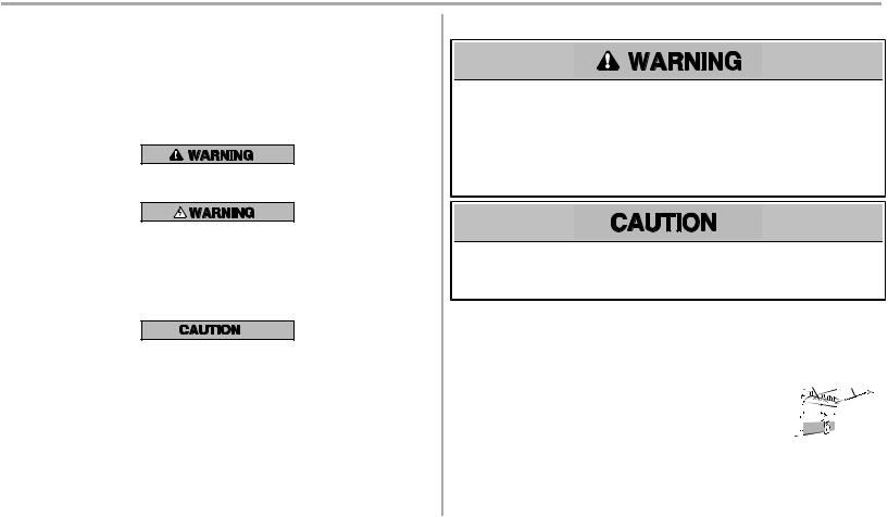
Safety Symbol and Signal Word Review
Thisgarage door opener hasbeen designed and tested to offer safe service provided itisinstalled, operated,maintained and tested in strictaccordance with the instructionsand warningscontained in this manual.
When you see these SafetySymbolsand Signal Wordson the following pages,theywill alertyou to the possibilityofserious injury ordeathifyou do notcomplywith the warningsthataccompanythem.The hazard maycome fromsomething mechanical or fromelectricshock.Read the warningscarefully.
Mechanical
Electrical
When you see thisSignal Word on the following pages,itwill alertyou to the possibilityofdamage to your garage door and/or the garage door opener ifyou do notcomplywith the cautionarystatementsthat accompanyit.Read themcarefully.
Check the Door
To preventpossible SERIOUS INJURY or DEATH:
•ALWAYS call a trained door systemstechnician ifgarage door binds,sticks,or isoutofbalance. An unbalanced garage door mayNOTreverse when required.
•NEVERtryto loosen,move or adjustgarage door,door springs,cables,pulleys,bracketsor their hardware,ALL ofwhich are under EXTREME tension.
•Disable ALL locksand remove ALL ropesconnected to garage door BEFORE installation and operating garage door opener to avoid entanglement.
To preventdamage to garage door and opener:
•ALWAYS disable locksBEFORE installing and operating the opener.
•ONLY operate garage door opener at120 V,60 Hzto avoid malfunction and damage.
1.Disable locksand remove anyropesconnected to the garage door.
2.Liftthe door halfwayup.Release the door.Ifbalanced,itshould stayin place,supported entirelybyitssprings.
3.Raise and lower the door to checkfor binding or sticking.Ifyour door binds,sticks,or isoutofbalance,call a trained door systems technician.
4.Checkthe seal on the bottomofthe door.Anygap between the floor and the bottomofthe door mustnotexceed 1/4 inch (6 mm). Otherwise,the safetyreversal systemmaynotworkproperly.
5.The opener should be installed above the center ofthe door.If there isa torsion spring or center bearing plate in the wayofthe header bracket,itmaybe installed within 4 feet(1.2 m) to the leftor rightofthe door center.See page 13.
Torsion Extension
Spring OR Spring
1
Preparation
Additional Items You May Need:
Surveyyour garage area to see ifyou will need anyofthe following items:
n(2) 2X4 PIECES OF WOOD
Maybe used to fasten the header bracketto the structural supports.Also used to position the garage door opener during installation and for testing the safetyreversing sensors.
nSUPPORT BRACKET AND FASTENING HARDWARE
Mustbe used ifyou have a finished ceiling in your garage.
nEXTENSION BRACKETS (MODEL 41A5281) OR WOOD BLOCKS
Depending upon garage construction,extension bracketsor wood blocksmaybe needed to install the safetyreversing sensor.
nFASTENING HARDWARE
Alternate floor mounting ofthe safetyreversing sensor will require hardware notprovided.
nOUTSIDE QUICK RELEASE (MODEL7702CB)
Required for a garage with NO accessdoor.
nDOORREINFORCEMENT
Required ifyou have a lightweightsteel,aluminum,fiberglassor glasspanel door.
nRAILEXTENSIONKIT
Required ifyour garage door ismore than 7 feet(2.13 m) high.
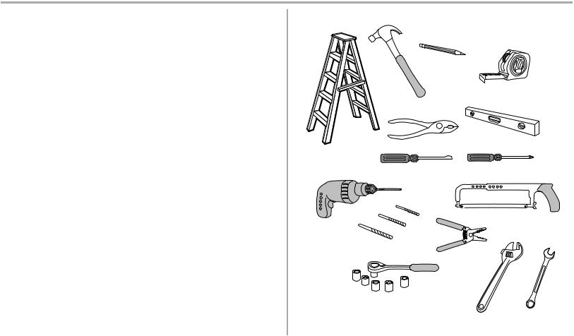
Tools Needed
1 |
2 |
5/32
3/16
5/16
1/2
5/8 |
|
1/4 |
|
|
|
7/16 |
9/16 |
7/16 |
|
|
2
Preparation
Carton Inventory |
|
|
|
Your garage door opener ispackaged in one carton which containsthe motor unitand all parts |
A |
|
|
illustrated below.Accessoriesvarydepending on the garage door opener model purchased.Depending |
|
||
|
|
||
on your model,other accessoriesmaybe included with your garage door opener.Instructionsfor these |
|
B |
|
accessorieswill be attached to the accessoryand are notincluded in thismanual.Ifanything ismissing, |
|
||
C |
F |
||
carefullycheckthe packing material.Hardware for assemblyand installation isshown on the nextpage. |
|||
|
|||
|
D |
||
Save the carton and packing material until the installation and adjustmentiscomplete.The images |
|
M |
|
throughoutthismanual are for reference onlyand your productmaylookdifferent. |
|
||
|
E |
A. |
Header bracket |
G |
|
B. |
Pulley |
H |
N |
C. |
Door bracket |
|
|
D.Curved door arm
E. |
Straight door arm (Packaged inside front rail section) |
K |
|
F. |
Trolley |
L |
|
|
NOTE: Be sure to assemble the trolley before sliding onto rail. |
|
|
G. |
Emergency release rope and handle |
|
|
H. |
Rail (1 front and 4 center sections) |
I |
|
|
|||
I. |
Hanging brackets (2) (Packaged inside the front rail section) |
|
|
J. |
Garage door opener (motor unit) |
|
|
K. |
Chain spreader with screws |
J |
|
L. |
“U” bracket |
||
|
M.Chain and cable
N.Door control
O. Remote control
P. The Protector System®
Safety reversing sensors with 2 conductor white and white/black wire attached: Sending Sensor (1), P
Receiving Sensor (1), and Safety Sensor Brackets (2)
NOT SHOWN
White and red/white wire
Owner's manual
3

Preparation
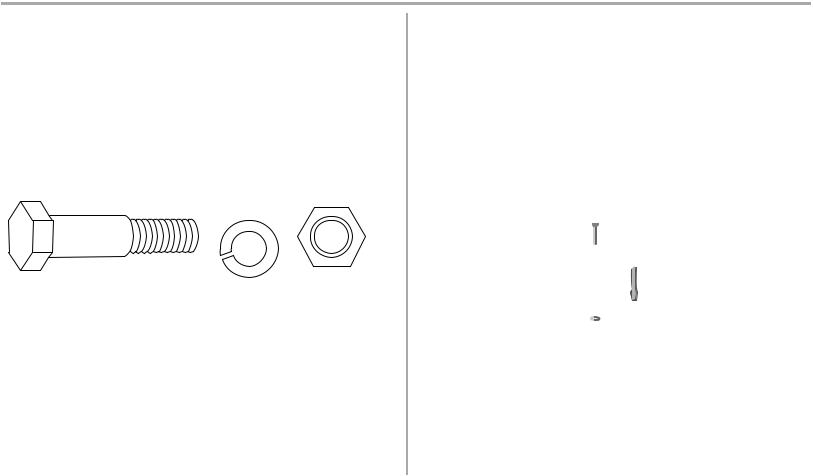
Hardware Inventory
ASSEMBLY HARDWARE
Bolt |
Bolt |
1/4"-20x1-3/4" |
|
Threaded
Shaft
Master Link
Lock Nut 1/4"-20
Nut 3/8" |
Lock Washer 3/8" |
INSTALLATION HARDWARE
Self-Threading Screw |
|
|
Lag Screw 5/16"-9x1-5/8" (4) |
||||||||||||||||||||||||||||||||
1/4"-14x5/8" (2) |
|
|
|||||||||||||||||||||||||||||||||
|
|
|
|
|
|
|
|
|
|
|
|
|
|
|
|
|
|
||||||||||||||||||
|
|
|
|
|
|
|
|
|
|
|
|
|
|
|
|
|
|
|
|
|
|
|
|
|
|
|
|
|
|
|
|
|
|
|
|
|
|
|
|
|
|
|
|
|
|
|
|
|
|
|
|
|
|
|
|
|
|
|
|
|
|
|
|
|
|
|
|
|
|
|
|
|
|
|
|
|
|
|
|
|
|
|
|
|
|
|
|
|
|
|
|
|
|
|
|
|
|
|
|
|
|
|
|
|
|
|
|
Clevis Pin 5/16"x1-1/2"
Carriage Bolt 1/4"-20x1/2" (2)
Nut 5/16"-18 (6)
Clevis Pin 5/16"x1-1/4" |
|
|
Clevis Pin 5/16"x1" |
|
|
||||
|
|
|
|
|
|
|
|
|
|
|
|
|
|
|
Wing Nut 1/4"-20 (2)
Hex Bolt 5/16"-18x7/8" (4)
Lock Washer 5/16"-18 (5)
Ring Fastener (3)
DOOR CONTROL HARDWARE
Screw 6-32x1" (2) |
|
||||||||||||||||||||
|
|
|
|
|
|
|
|
|
|
|
|
|
|
|
|
|
|
|
|
|
Insulated |
|
|
|
|
|
|
|
|
|
|
|
|
|
|
|
|
|
|
|
|
|
|
|
|
|
|
|
|
|
|
|
|
|
|
|
Screw 6ABx1" (2) |
Staples |
|||||||
|
|
|
|
|
|
|
|
|
|
|
|
|
(Not Shown) |
||||||||
Drywall Anchors (2)
4
Assembly
STEP 1 Assemble the rail and trolley
To preventINJURY frompinching,keep handsand fingersawayfromthe jointswhile assembling the rail.
To avoid installation difficulties,do not run the garage dooropeneruntilinstructed to do so.
The frontrail hasa cutout“window” atthe door end (see illustration).The hole above thiswindowis larger on the top ofthe rail than on the bottom.A smaller hole 3-1/2" (8.9 cm) awayisclose to the rail edge.Rotate the backrail so ithasa similar hole close to the opposite edge,about4-3/4" (12 cm) from the far end.
1.Remove the straightdoor armand hanging bracketpackaged inside the frontrail and set aside for Installation Step 5 and 9.NOTE: To preventINJURY while unpacking the rail carefullyremove the straightdoor armstored within the rail section.
2.Align the rail sectionson a flatsurface asshown and slide the tapered endsinto the larger ones.Tabsalong the side will lockinto place.
3.Place the motor uniton packing material to protectthe cover,and restthe backend ofthe rail on top.For convenience,puta supportunder the frontend ofthe rail.
4.Asa temporarystop,inserta screwdriver into the hole 10" (25 cm) fromthe frontend ofthe rail, asshown.
5.Checkto be sure there are 4 plasticwear padsinside the inner trolley.Iftheybecame loose during shipping,checkall packing material.Snap thembackinto position asshown.
6.Slide the trolleyassemblytoward the screwdriver asshown.
7.Slide the rail onto the “U” bracket,until itreachesall the stopson the top and sidesofthe “U” bracket.
Outer Trolley
Inner Trolley 

Wear Pads
Trolley
|
Rail |
|
Tab |
Front Rail |
Idler |
Section |
Pulley |
(TO DOOR) |
Hole |
|
Window |
|
Cut-Out |
To garage door opener
(TO MOTOR UNIT)
“U” Bracket 


SLIDE TO STOPS ON TOP AND SIDES OF
“U” BRACKET
5
Assembly
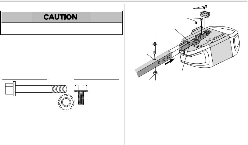
STEP 2 Fasten the rail to the motor unit
To avoid SERIOUS damage to garage door opener,use ONLY those bolts/fastenersmounted in the top ofthe opener.
1.Inserta 1/4"-20x1-3/4" boltinto the cover protection bolthole on the backend ofthe rail as shown.Tighten securelywith a 1/4"-20 locknut.Do NOTovertighten.
2.Remove the boltsfromthe top ofthe motor unit.
3.Use the carton to supportthe frontend ofthe rail.
4.Place the “U” bracket,flatside down onto the motor unitand align the bracketholeswith the boltholes.
5.Fasten the “U” bracketwith the previouslyremoved bolts;DO NOTuse anypower tools.The use ofpower toolsmaypermanentlydamage the garage door opener.
6.Attach spreader to the motor unitwith two screws.
HARDWARE
Bolts
(Mounted in the
garage door opener)
Bolt 1/4"-20x1-3/4"
Lock Nut 1/4"-20
HEX SCREWS
8-32X7/16
BOLTS
“U” BRACKET
BOLT 1/4"-20X1-3/4"
COVER
PROTECTION
BOLT HOLE
SLIDE RAIL TO
STOPS ON TOP AND
SIDES
LOCK NUT 1/4"-20
6
Assembly
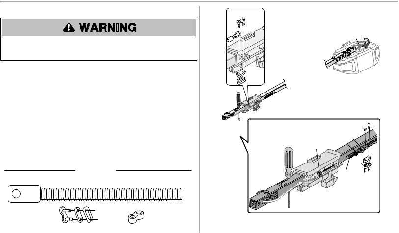
STEP 3 Install the idler pulley
1.Laythe chain/cable beside the rail,asshown.Grasp the end with the cable loop and pass approximately12" (30 cm) ofcable through the window.Allowitto hang until AssemblyStep 4.
2.Remove the tape fromthe idler pulley.The inside center should be pre-greased.Ifdry, regrease to ensure proper operation.
3.Place the idler pulleyinto the windowasshown.
4.Insertthe idler boltfromthe top through the rail and pulley.Tighten with a 3/8" lockwasher and nutunderneath the rail until the lockwasher iscompressed.
5.Rotate the pulleyto be sure itspinsfreely.
6.Locate the rail tab.The rail tab isbetween the idler boltand the trolleyin the frontrail section. Use a flathead screwdriver and liftthe rail tab until the tab isvertical (90º).
|
HARDWARE |
|
|
BOLT |
NUT 3/8" |
||
|
|||
|
|||
|
LOCK WASHER 3/8" |
||
CORRECT
Rail Tab
INCORRECT
Screwdriver
Rail
Bolt 
 Rail
Rail
Tab
Grease Inside Pulley
Lock Washer 3/8"
Nut 3/8" |
Idler Pulley |
|
7
Assembly
STEP 4 Install the chain |
A. |
||
|
|
|
|
|
|
|
|
|
|
|
|
|
|
|
|
To avoid possible SERIOUS INJURY to fingersfrommoving garage door opener:
• ALWAYS keep hand clear ofsprocketwhile operating opener.
• Securelyattach chain spreader BEFORE operating.
1. Pull the cable around the idler pulleyand toward the trolley. 2. Connectthe cable to the retaining sloton the trolley.(a)
a.Push pinsofmaster linkbar through cable linkand trolleyslot.
b.Push master linkcap over pinsand pastpin notches.
c.Slide clip-on spring over cap and onto pin notchesuntil both pinsare securely
locked in place.
3. With the trolleyagainstthe screwdriver,dispense the remainder ofthe cable/chain along the rail toward the motor unitinto the sloton the chain spreader,around the sprocketonto the chain spreader and continuing to the trolleyassemblyand continuing to the trolleyassembly. The sprocketteeth mustengage the chain.(b)
4.Thread the inner nutand lockwasher onto the trolleythreaded shaft.
5.Insertthe trolleythreaded shaftthrough the hole in the trolley.Be sure the chain isnot twisted.(c)
6.Looselythread the outer nutonto the trolleythreaded shaft.
7.Remove the screwdriver.
HARDWARE
THREADED SHAFT
MASTER
CHAIN LINK
LINK
C.
FRONT RAIL SECTION
(TO
B. Sprocket
Master Link 


Inner
|
Lock Nut |
Outer |
Washer |
|
|
Nut |
|
|
Master |
|
Link |
|
Threaded |
|
Shaft |
8
Assembly
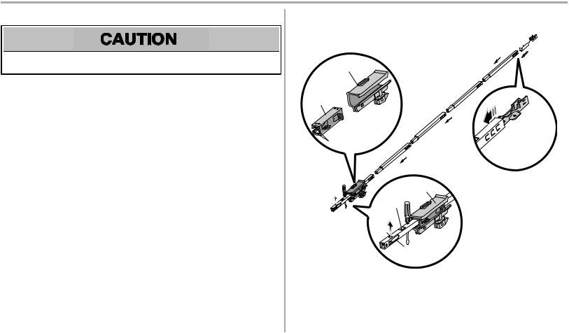
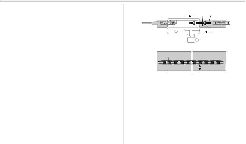
STEP 5 Tighten the chain
1.Spin the inner nutand lockwasher down the trolleythreaded shaft,awayfromthe trolley.
2.To tighten the chain,turn the outer nutin the direction shown.
3.When the chain isapproximately1/4" (6 mm) above the base ofthe rail atit'smidpoint,retighten the inner nutto secure the adjustment.
Sprocketnoise can resultifthe chain istoo loose.
When installation iscomplete,you maynotice some chain droop with the door closed.Thisisnormal.If the chain returnsto the position shown when the door isopen,do notre-adjustthe chain.
NOTES: During future maintenance,ALWAYS pull the emergencyrelease handle to disconnectthe trolleybefore adjusting the chain.
You maynotice loosening ofthe chain after AdjustmentStep 3 (Testthe SafetyReversal System).Check for proper tension and readjustchain ifnecessary.Then repeatAdjustmentStep 3.
Youhave now finishedassemblingyourgarage dooropener.Please readthe followingwarnings before proceedingtothe installationsection.
|
|
Trolley |
Outer |
Lock |
Threaded |
Nut |
Washer |
Shaft |
To Tighten Outer Nut |
|
|
|
|
Inner Nut |
|
To Tighten |
|
|
Inner Nut |
|
Chain
1/4" (6 mm)
Base of Rail |
Mid length of Rail |
9
Installation
IMPORTANT INSTALLATIONINSTRUCTIONS
To reduce the risk of SEVERE INJURY or DEATH:
1.READANDFOLLOWALL INSTALLATIONWARNINGS ANDINSTRUCTIONS.
2.Install garage door opener ONLY on properlybalanced and lubricated garage door.An improperlybalanced door mayNOTreverse when required and could resultin SEVERE INJURY or DEATH.
3.ALL repairsto cables,spring assembliesand other hardware MUSTbe made bya trained door systemstechnician BEFORE installing opener.
4.Disable ALL locksand remove ALL ropesconnected to garage door BEFORE installing opener to avoid entanglement.
5.Install garage door opener 7 feet(2.13 m) or more above floor.
6.Mountthe emergencyrelease within reach,butatleast6 feet(1.83 m) above the floor and avoiding contactwith vehiclesto avoid accidental release.
7.NEVERconnectgarage door opener to power source until instructed to do so.
8.NEVERwear watches,ringsor loose clothing while installing or servicing opener.Theycould be caughtin garage door or opener mechanisms.
9.Install wall-mounted garage door control:
•within sightofthe garage door.
•outofreach ofchildren atminimumheightof5 feet(1.5 m).
•awayfromALL moving partsofthe door.
10.Place entrapmentwarning label on wall nextto garage door control.
11.Place manual release/safetyreverse testlabel in plain viewon inside ofgarage door.
12.Upon completion ofinstallation,testsafetyreversal system.Door MUSTreverse on contact with a 1-1/2"(3.8 cm) high object(or a 2x4 laid flat) on the floor.
13.To avoid SERIOUS PERSONAL INJURY or DEATHfromelectrocution,disconnectALL electricpower BEFORE performing anyservice or maintenance.
14.DO NOTenable the Timer-to-Close functionalityifoperating either one-piece or swinging garage doors.To be enabled ONLY when operating a sectional door.
10
Installation |
|
|
|
|
STEP 1 Determine the header bracket location |
Header Wall |
|
OPTIONAL CEILING MOUNT |
|
|
|
|
||
|
Vertical Centerline of Garage Door |
FOR HEADER BRACKET |
||
|
2x4 |
Structural |
|
|
|
|
|
||
|
|
Supports |
Unfinished |
|
|
|
|
||
|
|
|
Ceiling |
|
To preventpossible SERIOUS INJURY or DEATH: |
|
|
|
|
• Header bracketMUSTbe RIGIDLY fastened to structural supporton header wall or ceiling, |
|
|
|
|
otherwise garage door mightNOTreverse when required.DO NOTinstall header bracketover |
|
|
|
|
drywall. |
Level |
|
|
|
• Concrete anchorsMUSTbe used ifmounting header bracketor 2x4 into masonry. |
|
|
||
(Optional) |
|
2x4 |
||
• NEVERtryto loosen,move or adjustgarage door,springs,cables,pulleys,brackets,or their |
|
|||
|
|
|||
|
|
|
||
hardware,ALL ofwhich are under EXTREME tension. |
|
|
|
|
• ALWAYS call a trained door systemstechnician ifgarage door binds,sticks,or isoutofbalance. |
|
|
|
|
An unbalanced garage door mightNOTreverse when required. |
Header Wall |
|
Header Wall |
|
|
2" (5 cm) |
|
2" (5 cm) |
|
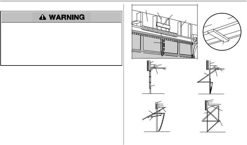
Installation proceduresvaryaccording to garage door types.Followthe instructionswhich applyto your |
Track |
Door |
Track |
|
Highest Point |
||||
door. |
|
Highest |
||
of Travel |
|
|||
1. Close the door and markthe inside vertical centerline ofthe garage door. |
|
|||
|
Point |
|||
|
|
|||
2. Extend the line onto the header wall above the door. |
Door |
|
of Travel |
|
You can fasten the headerbracket within 4 feet (1.22 m) of the left orright of the door |
|
|
|
|
centeronly if a torsion spring orcenterbearing plate is in the way; oryou can attach it to |
Sectional door with curved track |
One-piece door with horizontal track |
||
the ceiling when clearance is minimal.(It may be mounted on the wallupside down if |
||||
|
|
|
||
necessary,to gain approximately 1/2" (1 cm). |
Header Wall |
|
Header Wall |
|
Ifyou need to install the header bracketon a 2x4 (on wall or ceiling),use lag screws(not |
8" (20 cm) |
|
8" (20 cm) |
|
|
|
|||
provided) to securelyfasten the 2x4 to structural supports. |
Door |
|
Highest |
|
3. Open your door to the highestpointoftravel asshown.Drawan intersecting horizontal line on |
Highest |
Door |
||
Point of |
||||
the header wall 2" (5 cm) above the high point. |
Point of |
|
||
|
Travel |
|||
Travel |
|
|||
• 2" (5 cm) above the high pointfor sectional door and one-piece door with track. |
|
|
||
Jamb |
|
|
||
• 8" (20 cm) above the high pointfor one-piece door withouttrack.Thisheightwill provide travel |
Hardware |
|
Pivot |
|
clearance for the top edge ofthe door.NOTE: Ifthe total number ofinchesexceedsthe height |
|
|
||
|
|
|
||
available in your garage,use the maximumheightpossible,or refer to page 12 for ceiling |
One-piece door without track: |
One-piece door without track: |
||
installation. |
||||
jamb hardware |
pivot hardware |
|||
|
||||
11
Installation
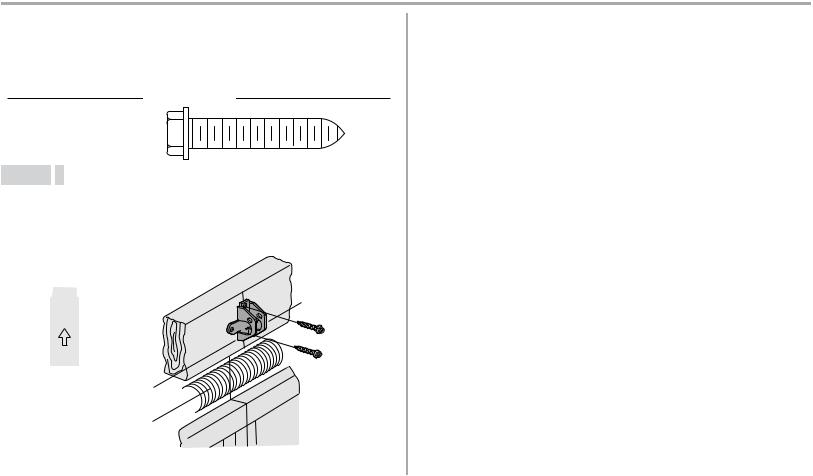
STEP 2 Install the header bracket
You can attach the header bracketeither to the wall above the garage door,or to the ceiling.Followthe instructionswhich will workbestfor your particular requirements.Do not installthe headerbracket over drywall.If installing into masonry,use concrete anchors (not provided).
HARDWARE
LAG SCREW 5/16"-9X1-5/8"
OPTION A WALL INSTALLATION
1.Center the bracketon the vertical centerline with the bottomedge ofthe bracketon the horizontal line asshown.
2.Markthe vertical setofbracketholes.Drill 3/16" pilotholesand fasten the bracketsecurelyto a structural supportwith the hardware provided.
Wall Mount |
(Header Wall) |
Vertical |
|
2x4 Structural |
|
Centerline of |
|
|
Garage Door |
||
Support |
|
||
|
|
||
UP |
Header |
|
|
|
Lag Screw |
||
Horizontal |
Bracket |
||
5/16"-9x1-5/8" |
|||
Line |
|
||
|
|
||
Optional Mounting |
|
Door Spring |
|
Holes |
|
||
|
|
||
Highest Point |
|
|
|
of Garage |
|
(Garage Door) |
|
Door Travel |
|
||
|
|
OPTION B CEILING INSTALLATION
1.Extend the vertical centerline onto the ceiling asshown.
2.Center the bracketon the vertical mark,no more than 6" (15 cm) fromthe wall.Make sure the arrowispointing awayfromthe wall.The bracketcan be mounted flush againstthe ceiling when clearance isminimal.
3.Markthe side holes.Drill 3/16" pilotholesand fasten bracketsecurelyto a structural support with the hardware provided.
Ceiling Mounting |
Header |
|
|
Bracket |
|
||
Holes |
(Finished Ceiling) |
||
|
6" (15 cm)

 Maximum UP
Door Spring
Vertical
Centerline of
Garage Door
Lag Screw 5/16"-9x1-5/8"
(Garage Door) |
(Header Wall) |
|
12
Installation
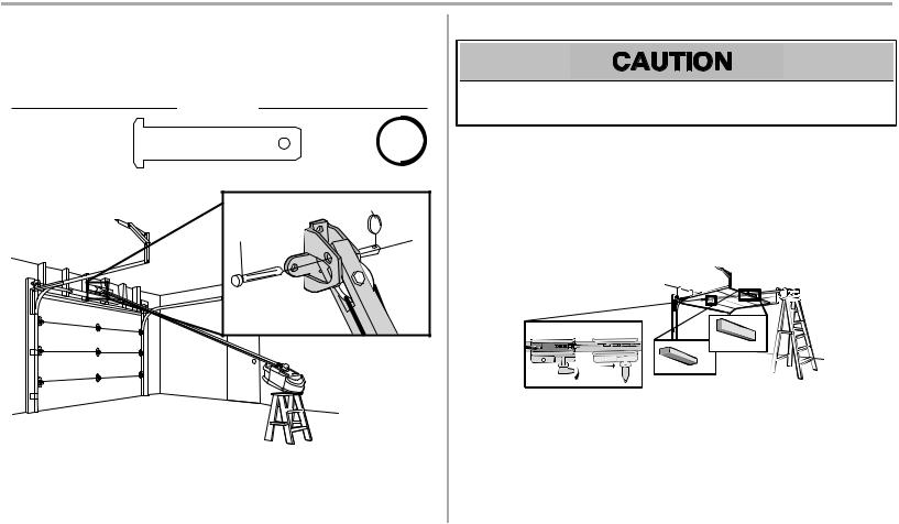
STEP 3 Attach the rail to the header bracket
1.Align the rail with the header bracket.Insertthe clevispin through the holesin the header bracketand rail.Secure with the ring fastener.
NOTE: Use the packing material asa protective base for the garage door opener.
HARDWARE
Clevis Pin 5/16"x1-1/2" |
|
|
Ring Fastener |
|
|
||
|
|
|
|
|
|
|
|
Ring Fastener |
Clevis Pin |
5/16"x1-1/2" |
STEP 4 Position the garage door opener
To preventdamage to garage door,restgarage door opener rail on 2x4 placed on top section of door.
1.Remove the packing material and liftthe garage door opener onto a ladder.
2.Fullyopen the door and place a 2x4 (laid flat) under the rail.For one-piece doorswithout tracks,laythe 2x4 on it'sside.
NOTE: A 2x4 isideal for setting the distance between the rail and the door.Ifthe ladder isnottall enough you will need help atthispoint.Ifthe door hitsthe trolleywhen itisraised,pull the trolleyrelease armdown to disconnectthe inner and outer trolley.Slide the outer trolleytoward the garage door opener.The trolleycan remain disconnected until instructed.
Connected Disconnected
|
|
One-piece |
|
|
door |
|
All other |
without tracks |
|
door types |
|
13
Loading...