


30MPA
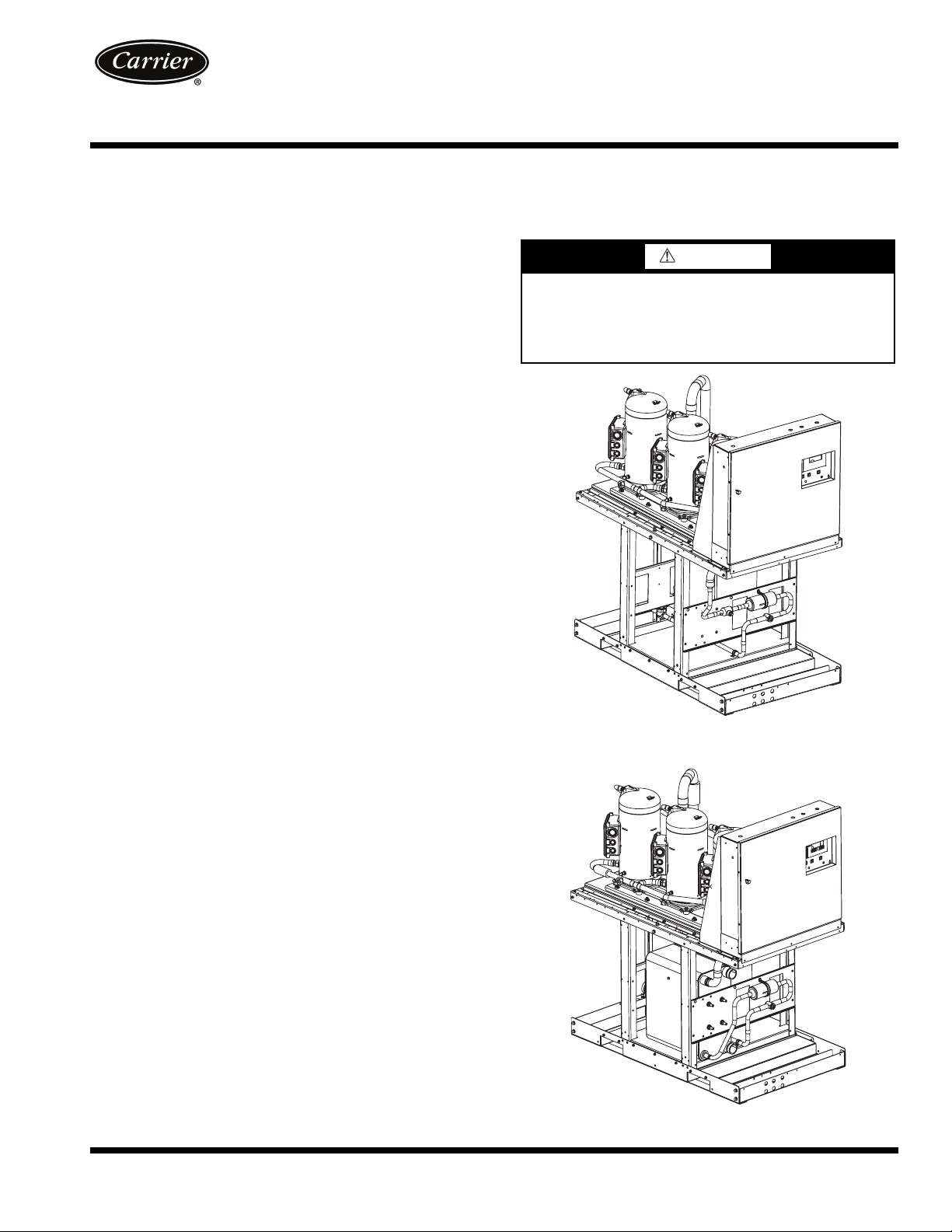
Fig. 1 — 30MPA Unit
a30-5029
Fig. 2 — 30MPW Unit
a30-5030
30MPA,MPW015-045
with Scroll Compressors
and COMFORTLINK™ Controls
Installation Instructions
AQUASNAP
®
Liquid Chillers
CONTENTS
Page
GENERAL . . . . . . . . . . . . . . . . . . . . . . . . . . . . . . . . . . . . . . 1
SAFETY CONSIDERATIONS . . . . . . . . . . . . . . . . . . . 1,2
INSTALLATION . . . . . . . . . . . . . . . . . . . . . . . . . . . . . . . . 2-16
Location. . . . . . . . . . . . . . . . . . . . . . . . . . . . . . . . . . . . . . . . 2
Step 1 — Inspect Shipment . . . . . . . . . . . . . . . . . . . . 2
Step 2 — Position the Unit . . . . . . . . . . . . . . . . . . . . . 2
Step 3 — Place the Unit. . . . . . . . . . . . . . . . . . . . . . . . 7
Step 4 — Check Compressor Mounting. . . . . . . . 7
Step 5 — Make Piping Connections. . . . . . . . . . . . 7
• 30MPA SYSTEM CONDENSER
• 30MPW CONDENSER DESCRIPTION
• 30MPW CONDENSER
• EVAPORATOR DESCRIPTION
• EVAPORATOR PIPING
•AIR SEPARATION
Step 6 — Fill the Chilled Water Loop. . . . . . . . . . .13
• WATER SYSTEM CLEANING
• FILLING THE SYSTEM
Step 7 — Make Electrical Connections. . . . . . . . .14
•FLOW SWITCH
• CONTROL BOX, POWER SECTION
• CONTROL BOX, CONTROLS SECTION
• CONTROL BOX, FIELD CONTROL WIRING
SECTION
• UNBALANCED 3-PHASE SUPPLY VOLTAGE
.
WARNING
Electrical shock can cause personal injury and death. Shut
off all power to this equipment during installation. There
may be more than one disconnect switch. Tag all disconnect locations to alert others not to restore power until work
is completed.
GENERAL
These installation instructions cover the 30MPA, MPW units
with ComfortLink controls. The 30MPA units are condenserless
units and the 30MPW units are all fluid cooled.
SAFETY CONSIDERATIONS
Installing, starting up, and servicing this equipment (Fig. 1
and 2) can be hazardous due to system pressures, electrical
components, and equipment location (roofs, elevated structures, etc.). Model number structure is shown in Fig. 3.
Only trained, qualified installers and service technicians
should install, start up, and service this equipment.
When working on the equipment, observe precautions in the
literature and on tags, stickers, and labels attached to the
equipment.
• Follow all safety codes.
• Wear safety glasses and work gloves.
• Use care in handling, rigging, and setting bulky
equipment.
Manufacturer reserves the right to discontinue, or change at any time, specifications or designs without notice and without incurring obligations.
Catalog No. 04-53300054-01 Printed in U.S.A. Form 30MP-1SI Pg 1 910 1-10 Replaces: New
INSTALLATION
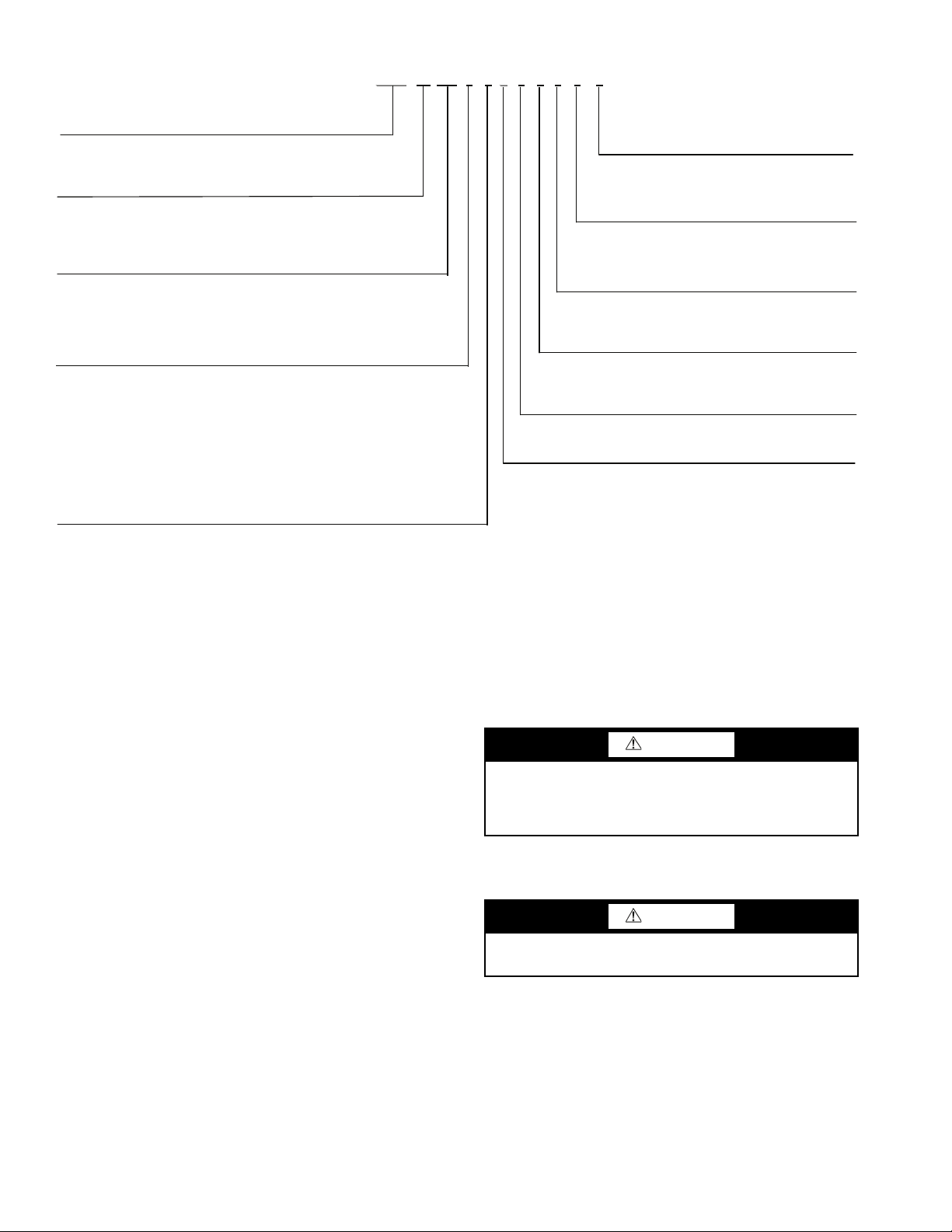
30MP
A0306 -
30MP – Aquasnap® Liquid Chiller with ComfortLink™ Controls
Condenser Option
A – Chiller without Condenser (Air-Cooled)
Design Revision Level
W – Chiller with Condenser (Water-Cooled)
- – Initial Release
Voltage Options
1 – 575-3-60
5 – 208/230-3-60
6 – 460-3-60
Unit Size – Nominal Tons (kW)
015 – 15 (54) 040 – 40 (138)
020 – 20 (71) 045 – 45 (161)
030 – 30 (108)
2 – 380-3-60
0
Sound/Mounting Options
0 – None
1 – S
ound Enclosure Panels
3 – Height Adjustment Kit
4 – Height Adjustment Kit, Sound Enclosure Panels
9 – Mobility Kit (Wheels)
B – Mobility Kit (Wheels), Sound Enclosure Panels
D – Height Adjustment Kit, Mobility Kit (Wheels)
F – Height Adjustment Kit, Mobility Kit (Wheels), Sound Enclosure Panels
0
Comfort Cooling/Medium Temp Brine Options
0 – Comfort Cooling Duty (32-60 F) (Std)
7 – Medium Temperature Brine (15-32 F)
0
Capacity Control Options
0 – Standard
1 – Hot Gas Byp
ass
0
Disconnect Options
0 – Standard (Terminal Block)
1 – Non-Fused Disconnect Switch
0
Controls/Interface Options
0 – Scrolling Marquee Display (Std)
5 – Scrolling Marquee Display, EMM
5
Packaging Options
5 – Bag
B – Export Crate
Fig. 3 — 30MP Model Number Nomenclature
LEGEND
EMM — Energy Management Module
LON — Local Operating Network
UPC — Unitary Protocol Controller
a30-5038
Location —
er because of sensitive control mechanisms and electronic
devices. Locate unit indoors. See Fig. 4 and 5 for unit dimensional details.
When considering location, consult National Electrical
Code (NEC) and local code requirements. Allow sufficient
space for wiring, piping, and service. Install unit in an area
where it will not be exposed to ambient temperatures below
50 F (10 C).
Allow 36 in. (914 mm) in front of the unit for control box
access door. Additional clearance may be required per local
codes. Prior to installation determine which direction compressor will be removed, and leave 3 to 4 ft (914 to 1219 mm)
clearance for removal.
On all units leave 3 ft (0.9 m) of clearance behind the unit to
make water/brine connections to the evaporator, accessing the
TXV (thermostatic expansion valve), fluid thermistors, and
proof of flow switch.
On all units, leave 2 ft (610 mm) on one side for making refrigeration connections (30MPA) or fluid connections
(30MPW) to condenser. See Fig. 4 and 5.
The floor must be strong enough to support the unit operating weight (see Tables 1A and 1B and Fig. 4-6). If necessary,
add a supporting structure (steel beams or reinforced concrete
slabs) to the floor to transfer weight to nearest beams.
Do not store units in an area exposed to weath-
Additional weight of factory-installed sound enclosure op-
tion is 75 lb (34 kg).
CAUTION
Be sure interconnecting piping and electrical conduits
Step 1 — Inspect Shipment — Inspect unit for dam-
age or missing parts. If damaged, or if shipment is incomplete,
file a claim immediately with the shipping company.
are suspended freely, and are not in contact with any
adjacent walls. Be sure unit capillaries are not rubbing
against anything. Damage to unit or walls may result.
Unit is top heavy. Unit may tip if handled without care.
Damage to unit or injury may result.
CAUTION
Step 2 — Position the Unit — The unit may be
moved by means of rollers under the rails or a forklift truck.
If accessory mobility kit is to be used, install this accessory
after bringing unit into building and before moving the unit to
its final location per installation instructions provided with the
accessory. The factory-installed mobility kit option consists of
4 swivel-type wheels that are field-mounted to the legs of the
unit. See Fig. 7.
NOTE: The wheels are equipped with a thumb-screw brake.
2
52.30
1328[]
STD UNIT 55.00
1397[]
OPTIONAL SOUND ENCLOSURE 57.00 [1448]
29.13
740[]
STD UNIT 32.00
813[]
62.50
1588[]
OPTIONAL SOUND ENCLOSURE 32.12 [816]
MOBILITY KIT
(WHEEL) OPTIONAL
3.85
98[]
E
D
F
OPTIONAL SOUND ENCLOSURE 48.42 [1230]
OPTIONAL
SOUND
ENCLOSURE
65.05
[1652]
4.00 [102]
ISOLATOR-OPTIONAL
C
B
A
4.03
102[]
1.75
44[]
4.46
[113]
UNIT
OPERATING
WEIGHT (lb)
ABCDEF
NO.OF
COMPRESSORS
30MPA015 626 (284 kg)
17.80
(452 mm)
25.10
(638 mm)
31.49
(800 mm)
5.54
(141 mm)
6.44
(164 mm)
18.50
(470 mm)
230MPA020 635 (288 kg)
17.60
(447 mm)
25.20
(640 mm)
31.39
(797 mm)
30MPA030 722 (327 kg)
17.00
(432 mm)
26.00
(660 mm)
30.69
(780 mm)
5.87
(149 mm)
11.12
(282 mm)
17.95
(456 mm)
30MPA040 913 (414 kg)
17.50
(445 mm)
25.90
(658 mm)
33.50
(851 mm)
5.99
(152 mm)
11.00
(279 mm)
17.72
(450 mm)
3
30MPA045 934 (424 kg)
17.40
(442 mm)
26.00
(660 mm)
33.49
(851 mm)
COMPRESSOR
(SEE TABLE FOR QTY)
OUT
IN
OPTIONAL SOUND
ENCLOSURE
FIELD CONNECTION
(4) 7/8" K.O
NON-FUSED
DISCONNECT
(OPTIONAL)
1/4" FPT
ACCESS
P,T
ACCESS
PORTS
1/4" SAE
FLARE RELIEF
CONNECTION
POWER
ENTRY
WATER CONNECTIONS
(IN/OUT)
2" VICTAULIC (015-020)
2 1/2" VICTAULIC (030-045)
COOLER
COOLER
COOLER
CONTROL PANEL END
OPPOSITE CONTROL PANEL END
MOUNTING HOLES 9/16"
-
MOUNTING HOLES 9/16"
-
IN
OUT
040,045 TON
ONLY
FORK POCKETS
SCROLLING
MARQUEE DISPLAY
REMOTE CONDENSER
CONNECTION
LIQ. LINE
ISOLATION VALVE
LIQ. LINE
SOLENOID
VALVE
CONTROL BOX
ACCESS DOOR
CLEARANCE
36"(914)
ENSURE CLEARANCE
PER LOCAL CODES
CONTROL PANEL
END OF UNIT
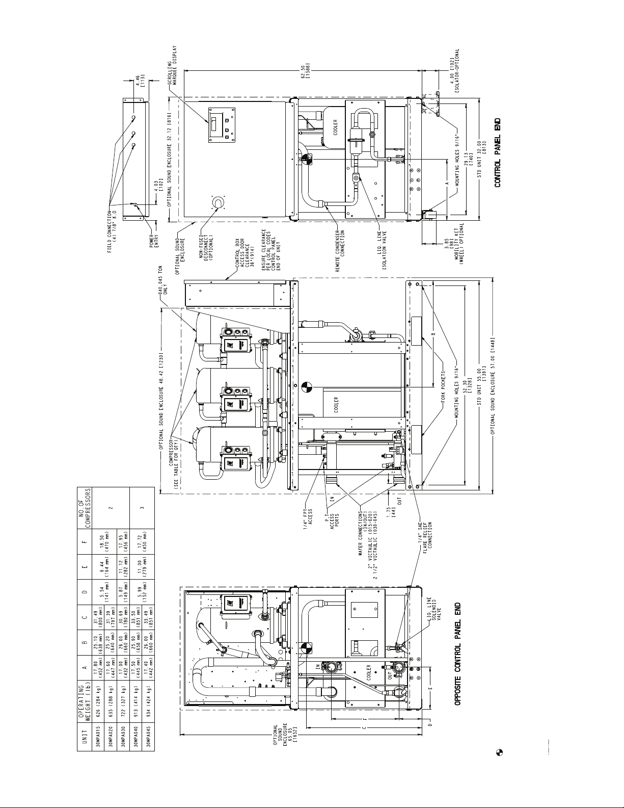
Fig. 4 — Dimensions — 30MPA015-045 Units
NOTES:
1. Operating weight includes weight of water and refrigerant.
2. Denotes center of gravity.
3. Dimensions are shown in inches. Dimensions in [ ] are in
millimeters.
4. Allow 36-in. (914 mm) clearance on control panel end, opposite
control panel end and above the unit. All clearances must be in
accordance with local codes.
5. Denotes accessory or factory-installed option.
a30-5032
3
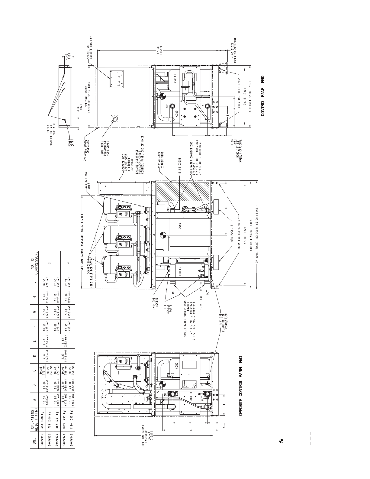
Fig. 5 — Dimensions — 30MPW015-045 Units
NOTES:
1. Operating weight includes weight of water and refrigerant.
2. Denotes center of gravity.
3. Dimensions are shown in inches. Dimensions in [ ] are in
millimeters.
4. Allow 36-in. (914 mm) clearance on control panel end, opposite
control panel end and above the unit. All clearances must be in
accordance with local codes.
5. Denotes accessory or factory-installed option.
a30-5033
910
4
Table 1A — 30MPA Air-Cooled and 30MPW Liquid-Cooled Units — English
UNIT 30MPA,MPW 015 020 030 040 045
NOMINAL TONS 15 20 30 40 45
OPERATING WT (lb)
MPA 626 635 722 913 934
MPW 680 704 862 1099 1190
REFRIGERANT (lb) R-410A
MPA —————
MPW 11.6 15.2 23.1 29.4 34.4
COMPRESSOR Scroll, Hermetic
Quantity 22233
Speed (rpm) 3500 3500 3500 3500 3500
Compressor Nominal Tons 7.510151315
Oil Charge (pt) 10.6 13.8 13.8 20.6 20.6
Capacity Control — Standard
No. of Steps 22233
Minimum Step Capacity (%) 50 50 50 33 33
Capacity Control — Optional Hot Gas Bypass
No. of Steps 33344
Minimum Step Capacity (%) 18 25 34 21 22
EVAPORATOR
Weight (lb, empty) 27.5 40.3 91.8 122.3 128.3
Net Fluid Volume (gal.) 0.8 1.2 2.4 3.2 3.4
Maximum Refrigerant Pressure (psig) 650 650 650 650 650
Maximum Fluid-Side Pressure (psig) 300 300 300 300 300
Water Connections (in.)
Inlet and Outlet (Victualic) 222
Drain (NPT)
CONDENSER (30MPW Only)
Weight (lb, empty) 34.9 43.6 104.6 136.7 188.3
Net Fluid Volume (gal.) 1.2 1.6 2.9 4.1 5.9
Maximum Refrigerant Pressure (psig) 650 650 650 650 650
Maximum Fluid-Side Pressure (psig) 300 300 300 300 300
Water Connections (in.)
Inlet and Outlet (Victualic) 222
1
/
2
1
/
2
CHASSIS DIMENSIONS (in.)
Length 55 55 55 55 55
Width 32 32 32 32 32
Height 63 63 63 63 63
MINIMUM SYSTEM FLUID VOLUME (gal. per Ton)
Normal Air Conditioning
Standard 66644
Optional Hot Gas Bypass 44433
Low Outdoor Ambient Cooling Operation (30MPA Units)
Standard 10 10 10 88
Optional Hot Gas Bypass 77766
CAPACITY STEPS
Step 1 100% 100% 100% 100% 100%
Step 2 50% 50% 50% 67% 67%
Step 3 18%* 25%* 34%* 33% 33%
Step 4 — — — 21%* 22%*
MINIMUM FLOW RATES (gpm)
Evaporator 22 28 43 55 64
Condenser 22 28 43 55 64
MAXIMUM FLOW RATES (gpm)
Evaporator 74 97 148 188 220
Condenser 74 97 148 188 220
* With optional hot gas bypass. NOTES:
1. Operating weight includes refrigerant operating charge and
weight of fluid in the heat exchangers.
2. 30MPW units are shipped with full operating charge.
1
/
2
1
/
2
1
/
2
2 1/
1
2 1/
2
/
2
2
21/
21/
2
1
/
2
2
5
 Loading...