


30RB060-390 Minimum Load Control Accessory
Installation Instructions
Part No: 00EFN900000100A
SAFETY CONSIDERATIONS
Installing, starting up, and servicing air-conditioning equipment can be hazardous due to system pressures, electrical components and equipment location.
Only trained, qualified installers and service technicians should install, start up, and service this equipment.
When working on air-conditioning equipment, observe precautions in the literature, on tags, stickers, and labels attached to the equipment.
Follow all safety codes. Wear safety glasses and work gloves. Use care in handling equipment.
 WARNING
Electrical shock can cause personal injury and death. Shut off all power to this equipment during installation. There may be more than one disconnect switch. Tag all disconnect locations to alert others not to restore power until work is completed.
GENERAL
IMPORTANT: This accessory can only be used on units configured for Cooler Fluid Type (ConfigurationSERV FLUD = 1 [Water]). The minimum load control accessory (HGBP) is not allowed on units configured for Cooler Fluid Type (Configuration SERV FLUD = 2 [Brine]).
This control accessory reduces 30RB chiller capacities below the standard lowest capacity step. This capacity reduction provides more precise control of leaving fluid temperature during light load conditions.
The solenoid valve limits the amount of gas that can be bypassed from the condenser without impacting oil return.
One accessory package is required for 30RB060-190 units and for each module of duplex units 30RB315-390. Two accessory packages are required for 30RB210-300 units to accommodate connections for all three refrigerant circuits. See Table 1 for modular unit combinations.
Table 1 — Modular Unit Combinations
UNIT SIZE |
MODULE A |
MODULE B |
30RBA315 |
30RBA160 |
30RBA160 |
30RBA330 |
30RBA170 |
30RBA160 |
30RBA345 |
30RBA170 |
30RBA170 |
30RBA360 |
30RBA190 |
30RBA170 |
30RBA390 |
30RBA190 |
30RBA190 |
NOTE: An “A” in the model number indicates the design series.
INSTALLATION
Examine the package contents for correct part numbers. If any of the components are damaged, file a claim with the shipping company and notify a Carrier representative.
See Table 2 for package contents. See Fig. 1 for dimensional drawings of tubes included in the kit.
The following material is field supplied:
•1/2 in. OD copper tubing
•standard 1/2 in. copper tube elbows and couplings as required
Install the Solenoid Valve
 WARNING
Shut off all power to the unit. Lock out and safety-tag all disconnects. Remove refrigerant charge from the circuits using an approved refrigerant recovery device before proceeding with this installation. Follow good piping practices. Severe personal injury could result.
1.Shut off power to the unit.
2.Remove refrigerant charge from the unit.
3.Locate the factory-supplied stub on the discharge line for each circuit. Locate the 1/2 in. NPT pipe plugs at the blank end of the cooler for 30RB110 circuit B and for both circuits A and B on 30RB060-300 units. See Fig. 2.
4.Remove the 1/2 in. NPT pipe plugs from the blank end of the cooler. Use an appropriate thread sealing compound and install one 1 in. — 14 O-ring seal adapter for each circuit. Lightly lubricate each O-ring and attach a 5/8 in. O-ring seal tube assembly to each adapter. This nut should be torqued to 30 ft-lb (40 N- m). For 30RB110 circuit A size only, use a tubing cutter to cut off the end of the stub tube. See Fig. 3.
5.Assemble the hot gas bypass line in the following order:
a.Remove the discharge stub tube and braze the correct beaded tube in place.
b.Braze the ball valve to the beaded tube.
c.Braze the solenoid valve into the line.
d.Using field-supplied tubing, connect the solenoid valve to the low side connection, either the cooler or the liquid line.
e.Clamp the 5/8-in. tube to the rail. See Fig. 4 and 5.
Use field-supplied 1/2 in. OD copper tubing and fittings (as required) to plumb from the solenoid valve outlet to either the adapter tube in the cooler or stub tube in the liquid line depending on unit size. Tube support brackets and 1/2 in. tubing clamps are provided with the kit. Install brackets to the bottom of the coil bases to support tubing.
Manufacturer reserves the right to discontinue, or change at any time, specifications or designs without notice and without incurring obligations.
Catalog No. 04-53300047-01 |
Printed in U.S.A. |
Form 30RB-16SI |
Pg 1 |
3-10 |
Replaces: 30RB-4SI |
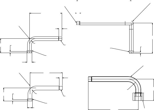
Table 2 — Contents of Accessory Kit
PART NUMBER |
QUANTITY |
DESCRIPTION |
USAGE |
|
00PPN500000600A |
2 |
5/8 in. tube assembly with 90-degree |
Blank end of the cooler except in |
|
bend and 1 in. — 14 O-ring seal nut |
30RB110 circuit A |
|||
|
|
|||
00PPN50001000A |
2 |
Solenoid valve with 1/2 in. |
All |
|
ODF connections |
|
|||
|
|
|
||
00PSN500023900A |
2 |
5/8 in. beaded tube with 1/2 in. swage |
30RB060,070,110,120, circuit A and |
|
(used with 11/8 in. discharge lines) |
30RB080-100 circuits A and B |
|||
|
|
|||
00PSN500024000A |
1 |
5/8 in. beaded tube with 1/2 in. swage |
30RB060,070 circuit B |
|
00PSN500024400A |
2 |
5/8 in. beaded tube with 1/2 in. swage |
30RB110,120 circuit B and |
|
(used with 15/8 in. discharge lines) |
30RB130-390 all circuits |
|||
|
|
|||
|
|
|
30RB060-110, circuit A (1 required) |
|
00PSN500023600A |
4 |
Tube support bracket |
30RB120,130 (2 required) |
|
30RB150 (3 required) |
||||
|
|
|
||
|
|
|
30RB160-390 (4 required) |
|
00PPN500000302A |
8 |
M6 screw |
All, mount tube support brackets |
|
00PPN500000401A |
7 |
No. 10 screw |
All, mount tube clamps |
|
EP71BA181 |
2 |
1/2 in. ball valve |
All, put in discharge line after solenoid |
|
valve so circuit can be isolated |
||||
|
|
|
||
30GX503492 |
2 |
1 in. — 14 ORS by 1/2 in. NPT adapter |
All at blank end of cooler except |
|
30RB110 circuit A |
||||
|
|
|
||
|
|
|
30RB060-110 (1 required) |
|
KA66AA050 |
5 |
|
30RB120,130 (2 required) |
|
1/2 in. tube clamp |
30RB150 (3 required) |
|||
|
|
|
30RB160,170,190, 315-390* (4 required) |
|
|
|
|
30RB210-300* (5 required) |
|
KA66AA062 |
2 |
5/8 in. tube clamp |
All, one per circuit just before solenoid |
|
SF703318 |
2 |
Cable assembly |
All, one per circuit |
*Requires two kits.
|
222.98 |
|||||||
|
Ø 12.7 [.50] SWAGE |
|
|
[8.78] |
|
|||
|
|
|
|
|
|
|||
126.73 |
|
|
|
|
|
12.33 |
|
|
[4.99] |
|
|
|
[0.49] |
|
|
||
|
|
|
|
|
|
MIN. |
||
|
|
|
|
|
|
|
|
|
|
|
|
|
|
|
|
|
|
|
00PSN500023900A |
|
|
|
|
|
|
12.33 |
|
|
|
|
[0.49] |
|
|
|
|
MIN. |
|
58.16 |
|
R25.40 |
Ø 12.7 [.50] SWAGE |
|
5.60 |
[1.00] |
|||
[2.21] |
||||
[0.22] |
|
|
||
|
|
BEAD |
||
|
|
|
||
|
|
|
BEAD |
|
|
20.11 MIN. |
|
|
|
|
[0.79] |
|
|
|
00PSN500024400AA |
|
126.73 |
||
|
|
|
[4.99] |
|
|
|
|
12.33 |
|
|
|
|
[0.49] |
|
|
|
|
MIN. |
|
|
|
|
R31.75 |
|
50.80 |
5.60 |
R25.40 |
[1.25] |
|
|
||||
[2.00] |
[0.22] |
[1.00] |
Ø 12.7 [.50] SWAGE |
|
BEAD
20.11 MIN.
[0.79] 152.40 [6.00]
NOTE: DIMENSIONS ARE IN MM [IN].
00PSN500024000A
123.98
[4.88]
5.60
[0.22]
00PPN500000600A
65.77
[2.59]
1in.-14 ORS NUT MUST MATE CORRECTLY WITH CARRIER ADAPTER 30GX503492
NOTE: Dimensions are in mm [in.].
Fig. 1 — Dimensions of Tubes Provided in Accessory Kit
2

DISCHARGE STUB
Fig. 2 — Typical Stub Tube View
COOLER STUB
Fig. 3 — Stub Tube for Circuit A of Size 110
BALL VALVE
Fig. 4 — Typical View of 5/8 in. Swage Tube, 5/8 in. Clamp and Solenoid Valve Installed
.
IMPORTANT: The valve is direction specific and must have the arrow pointing toward the cooler. The solenoid valve will not properly seat if installed backwards.
6.Dehydrate and recharge each circuit.
7.Restore power to the unit.
NOTE: When piping is completed, leak test the assembly. Then evacuate, dehydrate, and recharge the circuit using approved refrigeration practices. Be sure to use the correct type and amount of refrigerant listed in the nameplate data and base unit documentation.
Install Control Wiring (See Fig. 6 and 7)
1.One control wire harness is supplied per circuit. Secure the DIN connector end on the solenoid valve coil with the screw in the connector. Verify the square rubber gasket is in place to ensure connection remains watertight.
2.Route the other end of the cable to the main control panel (where the display is located). For the circuit A solenoid, connect leads to TB5-7 and TB5-13. For the B circuit solenoid, connect leads to TB5-8 and TB5-13. For the C circuit solenoid (30RB210-300 only), connect the leads to TB5-6 and TB5-13. In all cases the black wire from the solenoid must be connected to TB5-13 to ensure correct polarity. Incorrect polarity will damage the control boards.
3.For 30RB250-300 units only, locate fan board 3 (FB3) in the C circuit power control panel. Route the C circuit solenoid cable to the panel. Locate the orange and brown wires from channel 7 of connector J3 on this board. Connect the red wire from the solenoid to the orange wire from the board. Connect the black wire from the solenoid to the brown wire from the board.
Configure Unit for Minimum Load Control —
The control must be configured for the minimum load control operation. Use the scrolling marquee display to configure the system.
IMPORTANT: This accessory can only be used on units configured for Cooler Fluid Type (ConfigurationSERV FLUD = 1 [Water]). The minimum load control accessory (HGBP) is not allowed on units configured for Cooler Fluid Type (Configuration SERV FLUD = 2 [Brine]).
1.Set the Enable/Off/Remote switch to OFF position.
2.Press ESCAPE until the screen is blank and use the arrow key to select the Configuration mode LED (light emitting diode).
3.Press ENTER , then use arrow key to select the sub-mode ‘UNIT’, then press Enter key.
4.Press the down arrow key until ‘HGBP’ is displayed.
5.Press ENTER key twice. The word ‘PASS’ and ‘WORD’ will flash.
6.Press 0 1 1 1 then ENTER key so that ‘0’ flashes.
7. Use arrow keys to change value to one of the following configurations:
CONFIGURATION |
DESCRIPTION |
1Used during chiller start-up only
2Used during start-up and for close control of leaving fluid temperature
Used during start-up, for close control
3of the leaving fluid temperature and for high ambient unloading
3
 Loading...