


WFT-E7 B
Table of contents
 Loading...
Wireless File Transmitter
COPY
WFT-E7
To comply with local radio wave regulations, Canon offers five region-specific versions of the
transmitter (WFT-E7A, E7B, E7C, E7D, and E7E) in various areas around the world. (See
Areas of Use and Restrictions.) For convenience, we refer to the product in this manual simply
as “the transmitter,” without reference to versions A, B, C, D, or E.
E
INSTRUCTION MANUAL
Thank you for purchasing a Canon product.
COPY
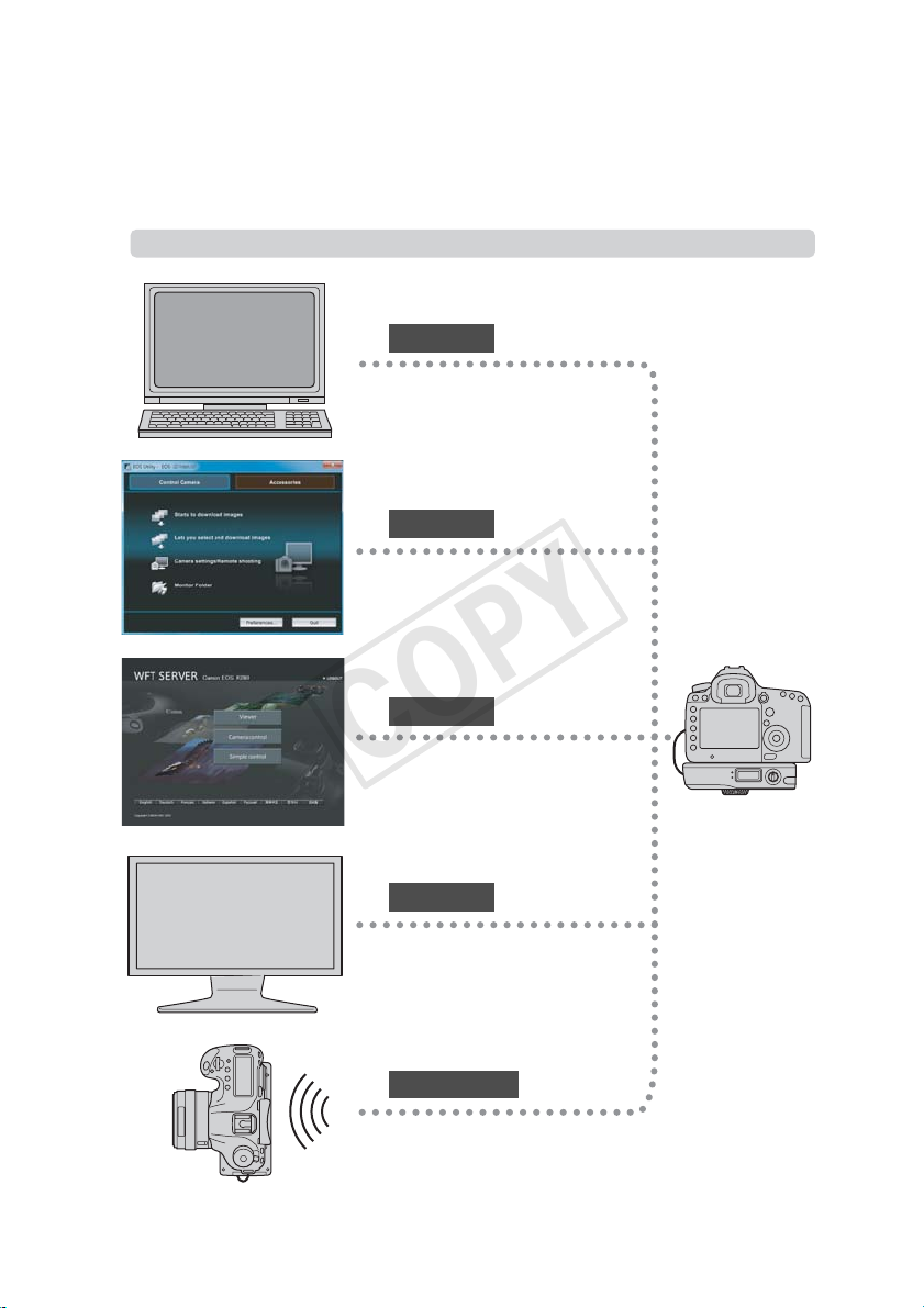
The Wireless File Transmitter WFT-E7 is an accessory for EOS cameras. In addition to time
synchronization with other cameras (over a wireless or wired LAN connection) and Bluetooth
connectivity with GPS devices, the transmitter enables the following operations.
Wireless and Wired LAN Functions
FTP TransferFTP Transfer
Transfer images to an FTP server
EOS Utility
Use EOS Utility to capture, view, and
download images remotely
WFT Server
Use a web browser to capture, view,
and download images remotely
Media Server
View images on a DLNA-compatible TV
or other devices
Linked Shooting
Wirelessly trigger shooting by slave
cameras linked to a master camera
2
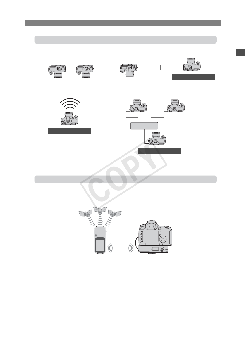
Sync the Camera Time over a Wireless or Wired Connection
COPY
Slave camera
Master camera
Connect to GPS Devices (commercially available) via Bluetooth
Slave camera
LAN cable
LAN cable
Slave camera
Hub
Master camera
Master camera
Connected via Bluetooth
Add the latitude, longitude, altitude, date and time, and
other shooting information to images
3

Conventions Used in this Manual
COPY
These instructions assume that your wireless or wired LAN and FTP server settings are
complete. For details on configuring these settings, refer to the documentation provided with
the respective equipment.
Terms in brackets [ ] indicate button or icon names or other software elements. Brackets
also denote camera menu items.
The EOS 5D Mark III is used as an example for illustrations and screens in this manual.
Note that the screens displayed on your camera may differ, depending on the camera model
used.
Page numbers in parentheses indicate where you can find additional information.
These instructions assume that you have read the Camera Instruction Manual and are
familiar with operating the camera.
Sections of this manual labeled with the following symbols contain information of the
corresponding nature.
: Warnings to avoid potential problems are labeled with a caution symbol.
: Supplemental information is labeled with a note symbol.
Windows is a trademark or registered trademark of Microsoft Corporation in the United
States and other countries.
Macintosh is a registered trademark of Apple Corporation in the United States and other
countries.
Wi-Fi is a registered trademark of the Wi-Fi Alliance.
Wi-Fi Certified, WPA, WPA2, and the Wi-Fi Certified logo are trademarks of the Wi-Fi
Alliance.
WPS as used on camera settings screens and in this manual signifies Wi-Fi Protected
Setup.
UPnP is a trademark of the UPnP Implementers Corporation.
Bluetooth and the Bluetooth logos are trademarks owned by Bluetooth SIG, Inc.
All other corporate and brand names in this manual are trademarks or registered
trademarks of their respective owners.
Using the transmitter for remote image transfer, capture, or viewing requires adequate knowledge of
configuring your wireless or wired LAN and FTP server.
Canon cannot provide support for configuring wireless or wired LANs or FTP servers.
Note that Canon cannot be held liable for any loss or damage to the transmitter from erroneous network
or FTP server settings. In addition, Canon cannot be held liable for any other loss or damage caused by
use of the transmitter.
4

Chapter List
COPY
1
2
3
4
5
6
7
Introduction
Basic Network Settings
Transferring Images to an FTP Server
Remote Capture Using EOS Utility
Remote Capture Using WFT Server
Using the Transmitter as a Media Server
Linked Shooting
Managing Settings Information
2
17
31
47
53
65
69
83
8
9
10
11
Synchronizing the Camera Time
Using Bluetooth GPS Devices
Troubleshooting
Reference
89
93
97
113
5

Contents
COPY
Introduction
Conventions Used in this Manual ...................................................................................................... 4
Chapter List........................................................................................................................................ 5
Contents............................................................................................................................................. 6
Safety Warnings................................................................................................................................. 8
Nomenclature..................................................................................................................................... 9
Installing and Removing the Battery ................................................................................................ 11
Using a Household Power Outlet ..................................................................................................... 13
Attaching to the Camera .................................................................................................................. 14
Subsequent Organization of This Manual........................................................................................ 16
1 Basic Network Settings 17
Getting Ready.................................................................................................................................. 18
Displaying the Connection Wizard................................................................................................... 19
Selecting the Communication Method and LAN Type ..................................................................... 20
Using the Wizard to Establish a Connection.................................................................................... 23
WPS Connections (PBC Mode)....................................................................................................... 25
WPS Connections (PIN Mode) ........................................................................................................ 26
Configuring Network Settings .......................................................................................................... 27
2 Transferring Images to an FTP Server 31
Configuring FTP Communication Settings....................................................................................... 32
Automatic Image Transfer After Each Shot ..................................................................................... 34
Transferring Images Individually ...................................................................................................... 37
Batch Transfer ................................................................................................................................. 40
Checking Image Transfer History .................................................................................................... 45
3 Remote Capture Using EOS Utility 47
Configuring EOS Utility Communication Settings ............................................................................ 48
Using EOS Utility ............................................................................................................................. 51
4 Remote Capture Using WFT Server 53
Configuring WFT Server Communication Settings .......................................................................... 54
Displaying WFT Server .................................................................................................................... 56
Viewing Images................................................................................................................................ 57
Remote Capture [Camera control]................................................................................................... 59
Remote Capture [Simple control]..................................................................................................... 62
Remote Capture............................................................................................................................... 63
Using WFT Server in Linked Shooting............................................................................................. 64
5 Using the Transmitter as a Media Server 65
Configuring Media Server Communication Settings ........................................................................ 66
Displaying Captured Images on a Television ................................................................................... 67
6

Contents
COPY
6 Linked Shooting 69
Preparing Slave Cameras ................................................................................................................ 70
Basic Linked Shooting ..................................................................................................................... 71
Positioning the Slave Cameras........................................................................................................ 72
Using the Transmitter with WFT Server ........................................................................................... 74
7 Managing Settings Information 83
Checking Settings ............................................................................................................................ 84
Changing Settings............................................................................................................................ 85
Saving and Loading Settings........................................................................................................... 87
8 Synchronizing the Camera Time 89
Preparing for Time Synchronization................................................................................................. 90
Synchronizing the Time ................................................................................................................... 91
9 Using Bluetooth GPS Devices 93
Connecting GPS Devices via Bluetooth........................................................................................... 94
10 Troubleshooting 97
Handling Error Messages ................................................................................................................ 98
Wireless LAN Notes ....................................................................................................................... 111
Checking Network Settings ............................................................................................................ 112
11 Reference 113
Creating and Registering Captions................................................................................................ 114
Using a Bracket (Sold Separately) ................................................................................................. 115
Specifications................................................................................................................................. 116
Index .............................................................................................................................................. 124
7

Safety Warnings
COPY
The following precautions are intended to prevent harm to you and others as well as damage to
equipment. Become familiar with the precautions before using the transmitter to ensure correct
and safe operation.
Be sure that you fully understand the safety precautions contained in the instruction manuals
for the battery, charger, and AC Adapter Kit before using them.
Warning Preventing Serious Injury or Death
To prevent fire, excessive heat, chemical leakage, or explosion, follow these safety guidelines.
• Do not insert metallic objects between electrical contacts of the transmitter, accessories, or connecting cables.
Do not use the transmitter where there is flammable gas. There is a risk of explosion or fire.
If the transmitter is dropped and internal parts are exposed, do not touch the exposed parts. There is a risk of
electrical shock.
Do not disassemble or modify the transmitter. High-voltage internal parts may cause electrical shock.
Do not store the transmitter in dusty or humid places. There is a risk of fire or electrical shock.
Before using the transmitter on board airplanes or in hospitals, make sure use is permitted. Electromagnetic
waves emitted by the transmitter may interfere with instrumentation or medical equipment.
Caution Preventing Injury or Equipment Damage
Do not leave the transmitter inside a vehicle in hot weather or near a heat source. The transmitter may become
hot and cause burns if touched.
Do not cover or wrap the transmitter with a cloth. This may trap heat inside, posing a risk of case deformation or
fire.
Do not use paint thinner, benzene, or other organic solvents to clean the transmitter. This poses a risk of fire and
may be hazardous to your health.
If the product malfunctions, becomes damaged, or requires repair, contact your dealer
or the nearest Canon Service Center.
Handling Precautions
The transmitter is a precision instrument. Do not drop it or subject it to shock.
The transmitter is not waterproof. Do not use it underwater.
Wipe off any moisture with a clean, dry cloth. If the transmitter has been exposed to salty air,
wipe it with a clean damp cloth after wringing it out to remove excess water.
Never leave the transmitter near any equipment that generates a strong magnetic field,
such as magnets or electric motors.
Do not leave the transmitter in excessive heat, such as in a vehicle in direct sunlight. High
temperature may damage the transmitter.
Do not wipe the transmitter using cleaners containing organic solvents. If the transmitter
becomes difficult to clean, take it to the nearest Canon Service Center.
To avoid corrosion, do not store the transmitter where there are strong chemicals, such as in
darkrooms or chemical labs.
8
Nomenclature
COPY
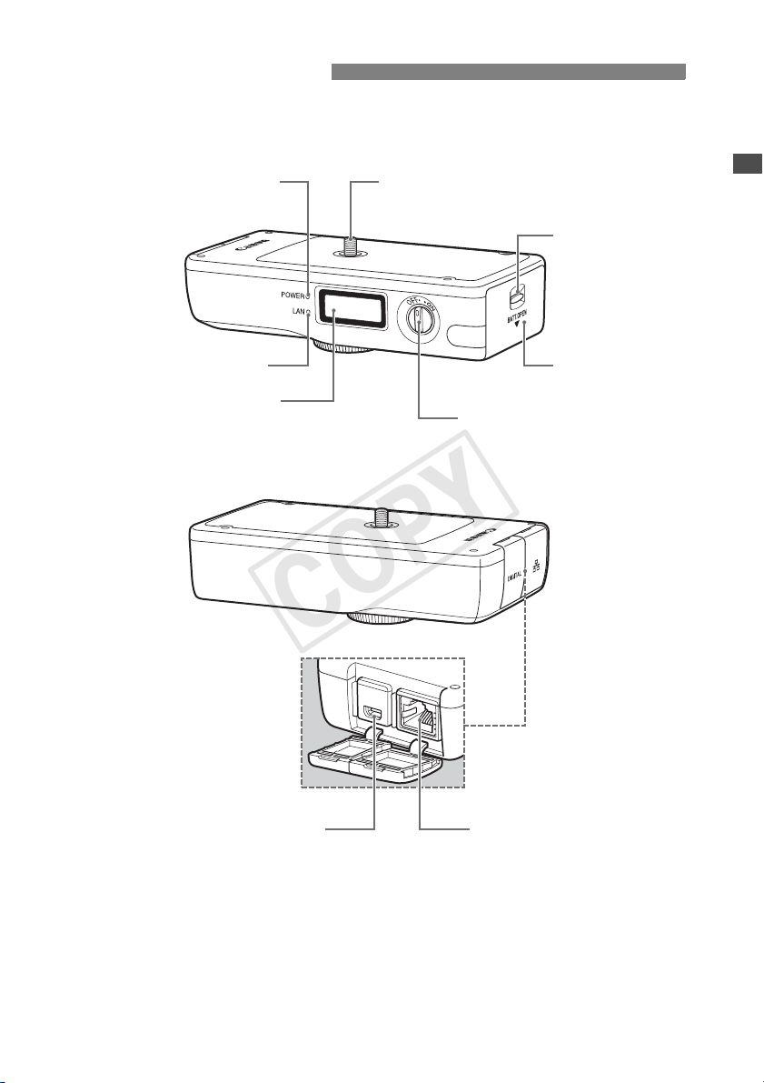
For detailed information, reference page numbers are provided in parentheses (p.**).
Powe r lamp
(p.14)
LAN
> lamp
<
LCD panel (p.10)
Tripod screw
Battery compartment
cover release lever
(p.11)
Battery compartment
cover (p.11)
Power switch (p.14)
<a> port (p.14)
Ethernet RJ-45 port
9
Nomenclature
C
COPY
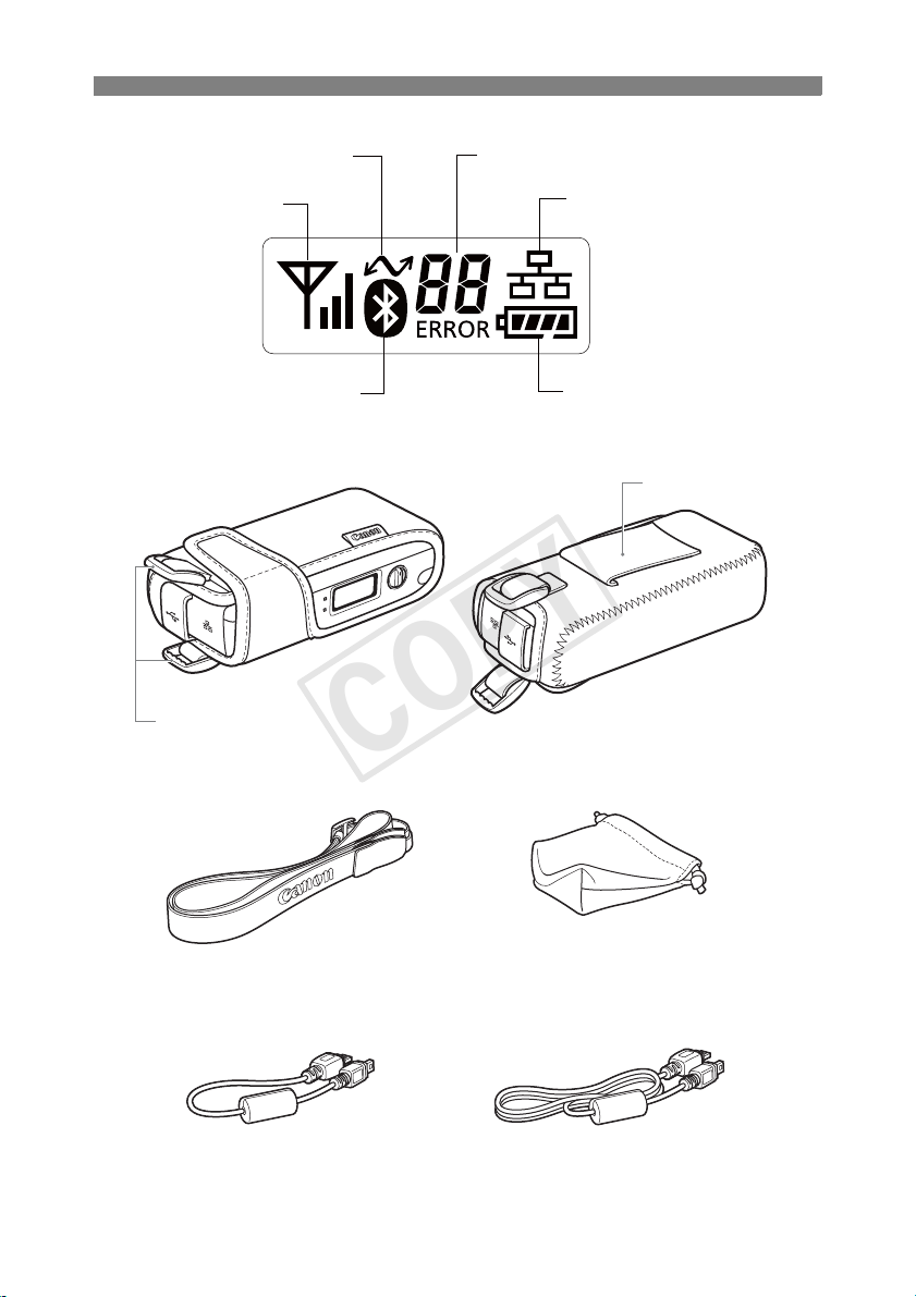
LCD panel
onnection icon
Error number
Wireless signal strength
Bluetooth connection
Case
Strap mounts
Wired LAN connection
Battery check
Belt holder
Case strap Case for tripod screw
Interface cables
10
Approx. 1.5 m / 4.9 ft.Approx. 25 cm / 9.8 in.
Installing and Removing the Battery
COPY
Use one Battery Pack LP-E6 to power the transmitter. When replacing the transmitter’s battery,
be sure to turn the transmitter off before opening the battery compartment cover.
Also note that the transmitter is not sold with a battery or charger. If you do not own these
accessories, they are available for purchase separately.
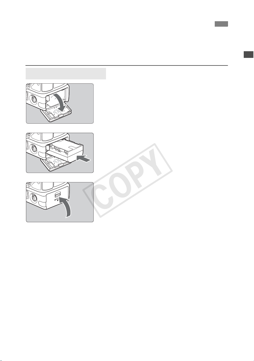
Installing the battery
Open the cover.
1
Push the lever down and open the cover.
Insert the battery.
2
Insert the end with the battery contacts.
Insert the battery all the way until it locks into
place.
Close the cover.
3
Press the cover up until it clicks into place.
11
Installing and Removing the Battery
COPY
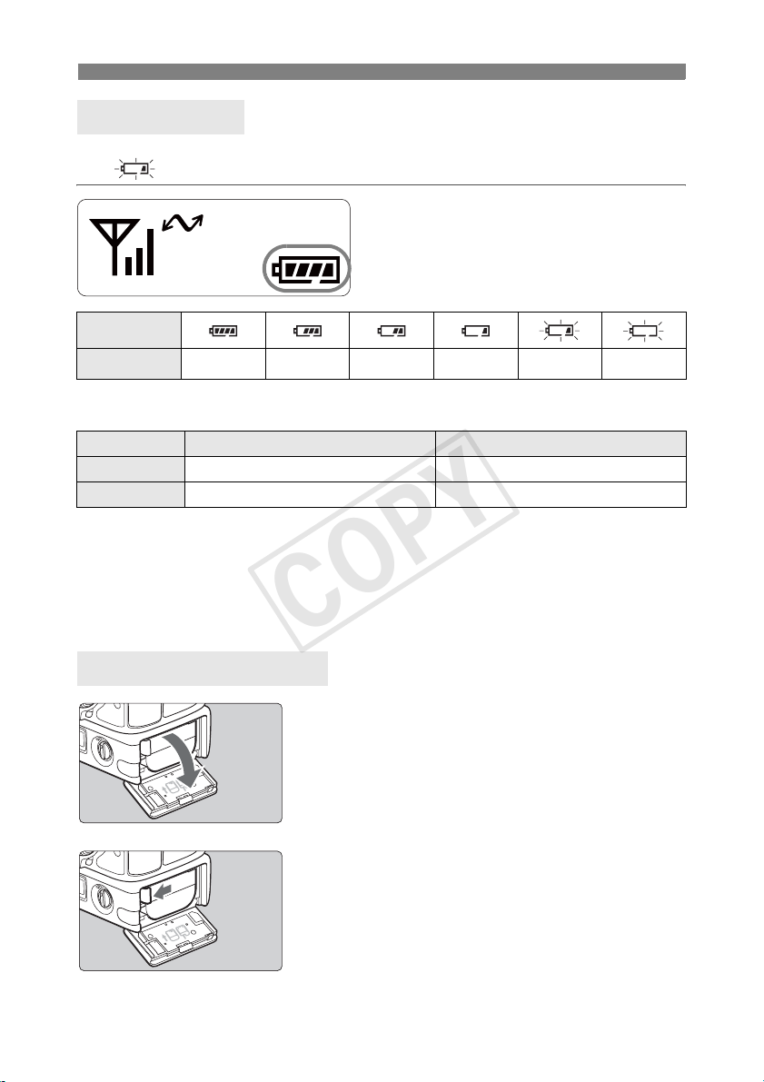
Battery check
The remaining battery power is displayed when you turn the transmitter on. A blinking battery
icon ( ) indicates that the battery will be depleted soon.
Icon
Level (%) 100 – 70 69 – 50 49 – 20 19 – 10 9 – 1 0
Number of images that can be transferred Approx. number of images
LAN At Normal Temperature (23°C / 73°F) At Low Temperature (0°C / 32°F)
Wireless LAN 2400 2300
Wired LAN 2200 2200
When using a fully charged LP-E6. The number of images that can be transferred is nearly
the same at normal temperature (23°C / 73°F) and low temperature (0°C / 32°F).
When automatic transfer is performed during shooting of an image of approx. 5 MB under
conditions based on the CIPA (Camera & Imaging Products Association) test standards.
Fewer images can be transferred when transferring images continuously over a wireless
LAN.
Removing the battery
12
Open the cover.
1
Push the lever down and open the cover.
Remove the battery.
2
Press the battery lock lever in the direction of the
arrow to unlock, and then remove the battery.
To prevent a short-circuit, be sure to always attach
the protective cover to the battery.
Using a Household Power Outlet
COPY
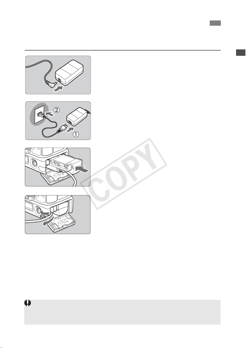
When the AC Adapter Kit ACK-E6 (sold separately) is used, a household power outlet can be
used to power the transmitter without worrying about the battery level.
Connect the DC coupler plug.
1
Connect the DC coupler plug to the socket of the
AC adapter.
Connect the power cord.
2
Connect the power cord as shown.
Insert the plug into the outlet.
After usage, unplug from the outlet.
Insert the DC coupler.
3
Open the cover, and insert the DC coupler firmly
until the lock position.
Close the cover.
4
Pass the cord through the groove while opening
the cap of the DC coupler cord notch, and then
close the cover.
Do not connect or disconnect the power cord while the transmitter’s power switch is set to <ON>.
Do not connect and use AC Adapter Kits ACK-E6 with both the camera and transmitter WFT-E7
simultaneously. It may cause malfunction to the nearby electronic devices. For more information,
contact a Canon Service Center.
13
Attaching to the Camera
COPY
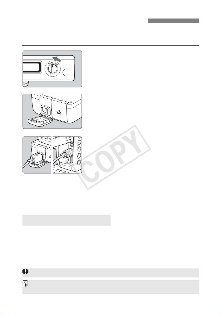
When connecting the transmitter to the camera, always use one of the interface cables
included with the transmitter.
Turn off both the camera and
transmitter.
1
Attach the transmitter’s <a> port
cap.
2
To keep the cable securely connected, attach the
cap to the transmitter.
Connect the transmitter and camera.
3
Connect the end of the cable with the <
logo to the transmitter’s <a> terminal.
Connect the end of the cable with the <
logo to the camera’s <a> terminal.
WFT GPS
CAMERA
>
>
Turn on both the camera and
transmitter.
4
X The transmitter’s <3> lamp will light and
<D> will be displayed on the transmitter’s LCD
panel.
Using the Interface Cables
Use the 25 cm / 9.8 in. cable when the transmitter is attached to the camera tripod socket or
Accessory Bracket AB-E1 (sold separately, p.115).
Use the 1.5 m / 4.9 ft. cable when the transmitter is stored in the included case and either
worn over your shoulder or attached to a belt.
Before disconnecting the cable, turn off both the transmitter and camera.
If the transmitter’s <3> lamp blinks, it means that the transmitter and camera are not properly
connected. Check the connection.
14
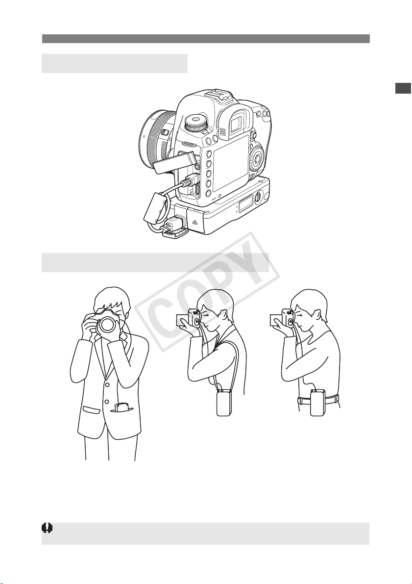
Example of Attachment
COPY
Example of Using the Case and Strap
Attaching to the Camera
If you turn on/off the transmitter or connect/disconnect the interface cable during Live View shooting or
movie shooting, Live View shooting or movie shooting will stop.
15

Subsequent Organization of This Manual
COPY
Click one of the following chapter titles to view the corresponding page.
1 Basic Network Settings (p.17)
2 Transferring Images to an FTP Server (p.31)
3 Remote Capture Using EOS Utility (p.47)
4 Remote Capture Using WFT Server (p.53)
5 Using the Transmitter as a Media Server (p.65)
6 Linked Shooting (p.69)
7 Managing Settings Information (p.83)
8 Synchronizing the Camera Time (p.89)
9 Using Bluetooth GPS Devices (p.93)
16

Basic Network Settings
COPY
Complete the basic network settings by following the transmitter’s
connection instructions on the camera menu screen.
17

Getting Ready
COPY
[FTP trans.], [EOSUtility], [WFTserver]
The connection instructions help you follow the steps to connect the transmitter to an existing
wireless or wired LAN.
To connect to a wireless LAN, prepare the wireless LAN terminal (wireless LAN access point or
wireless LAN adapter) and computer in advance so that they are ready for you to connect the
transmitter to the wireless network. When configuring the basic network settings, bring the
transmitter within 3 m / 9.8 ft. of the wireless LAN terminal.
To connect to a wired LAN, use a LAN cable to connect the transmitter and computer. Set the
transmitter for connection to the wired network.
Wireless transfer of movies
Individual movie files are large, and wireless file transfer takes some time. When setting up an
environment for stable transmission to the wireless LAN terminal, see the information on page
111.
[MediaServ.]
Set up a DLNA*-compatible television, digital photo frame, or similar media player so that it is
ready for use after the transmitter is connected to its network.
* DLNA: Digital Living Network Alliance
[LinkedShot]
Set up multiple cameras, including cameras with this transmitter attached and other cameras
compatible with linked shooting that have WFT units attached.
18
Displaying the Connection Wizard
COPY
This section’s explanation follows the flow of the connection instructions. If an error is
displayed, see “Troubleshooting” in Chapter 10 (p.97) and check the settings.
Pressing the shutter button or other camera controls during configuration will cause the
connection instructions to close. Do not press the shutter button or other controls until
configuration is finished.
In the menu, set [Auto power off] to [Disable]. If auto power off is activated, the connection
instructions close during the configuration process.
Turn on both the camera and
transmitter.
1
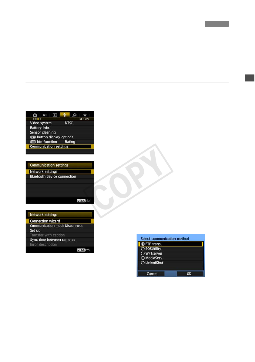
Display the transmitter menu.
2
On the camera, press the <7> button.
In the menu, select [Communication settings]
and press <0>.
Select [Network settings].
3
Select [Connection wizard].
4
X The [Select communication method] screen is
displayed.
X The <
LAN
> lamp on the transmitter starts blinking.
19

Selecting the Communication Method and LAN Type
COPY
Selecting the Communication Method
Turn the <5> dial to select the communication
method, and then press <0>.
Select [OK] and press <0> to go to the next
screen.
• FTP trans.
Select this option to transfer captured images to an FTP server.
Images can be automatically transferred as you shoot them, or you can select images to be
transferred later.
Computer Operating Systems
Use of [FTP trans.] requires that one of the following operating systems be installed on your
computer. In addition, the computer must be set up as an FTP server in advance.
• Windows 7 (Professional, Enterprise, or Ultimate Edition for 32- or 64-bit systems)
• Windows Vista (Business, Enterprise, or Ultimate Edition for 32- or 64-bit systems)
• Windows XP Professional
• Mac OS X 10.6 or 10.7
For instructions on setting up your computer as an FTP server, refer to the computer
documentation.
The following operating systems cannot be used because FTP server functionality is
not provided.
• Windows 7 Home Premium
• Windows Vista Home Premium/Home Basic Edition
• Windows XP Home Edition
• EOSUtility
Select this option for remote capture over a wireless or wired LAN using the EOS Utility
software included with your camera.
In addition to remote capture, all camera operations in EOS Utility are supported. With this
option, a wireless or wired network is used instead of the USB cable.
Requires a computer with EOS Utility (software included with EOS digital cameras)
installed.
20

Selecting the Communication Method and LAN Type
COPY
• WFTserver
Select this option for remote capture over a wireless or wired LAN with the transmitter acting as
a server.
Additionally, images on a memory card in the camera can be viewed and downloaded to a
computer.
The camera can be accessed in the same way as browsing a web page, by users at up to three
computers.
Computer Operating Systems
Any computer with a web browser can be used, regardless of the operating system.
Devices other than computers that feature a web browser can also be used. However, if the
web browser does not support JavaScript, WFT Server functions will be limited. Also note
that devices with limited performance may display images more slowly, and downloading
images to these devices may not be possible.
• MediaServ.
Select this option to view images on a memory card in the camera over a wireless or wired LAN
on a television.
This function requires a DLNA-compatible television, digital photo frame, or similar media
player.
• LinkedShot
Select this option for linked shooting, using multiple cameras compatible with linked shooting
that have WFT units attached. Up to 10 slave cameras can be linked to the master camera on
which you will release the shutter. Note that there will be a slight delay after you release the
master camera shutter before the slave cameras shoot. Movie shooting is not supported.
For further instructions on [LinkedShot], see page 69 of this manual.
21
Selecting the Communication Method and LAN Type
COPY
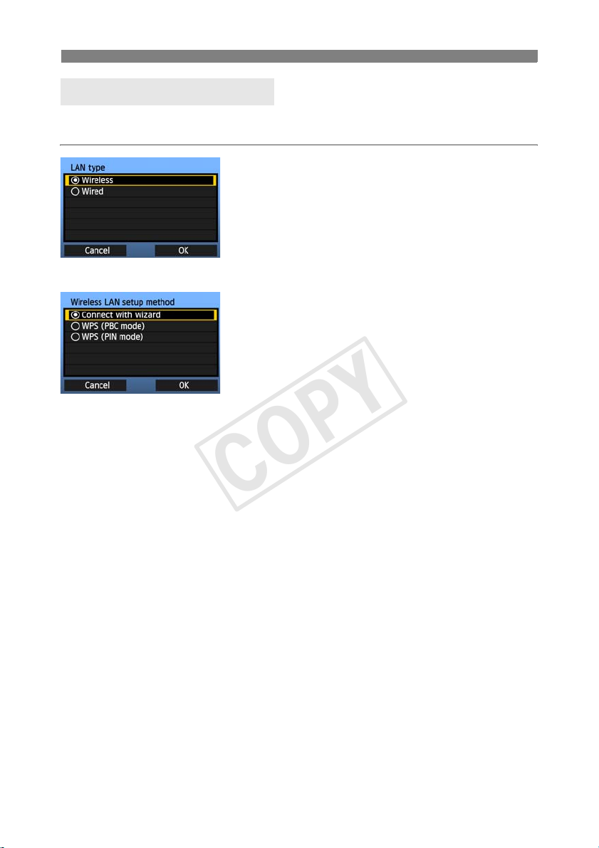
Selecting the LAN Type
For [LinkedShot] instructions, see page 69. Note that no information about [LinkedShot]
is given in this chapter.
Turn the <5> dial to select the type of LAN, and
then press <0>.
Select [OK] and press <0> to go to the next
screen.
Wireless LAN
The [Wireless LAN setup method] screen is
displayed.
[Connect with wizard]: See p.23
[WPS (PBC mode)]: See p.25
[WPS (PIN mode)]: See p.26
Select [WPS (PBC mode)] or [WPS (PIN mode)]
when using a wireless LAN terminal compatible with
Wi-Fi Protected Setup (WPS).
Wired LAN
The [Network] settings screen is displayed. If you have selected a wired network, see page 27,
“Configuring Network Settings.”
Use a Category 5e or higher STP LAN cable. (STP: Shielded Twisted Pair)
22
Using the Wizard to Establish a Connection
123 4
COPY
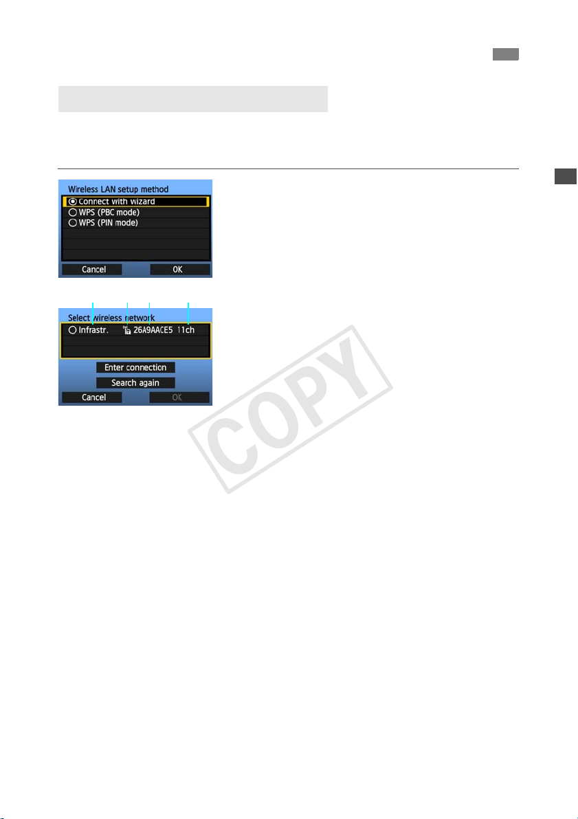
Selecting the Wireless Network
When you select [Connect with wizard], active wireless LAN terminals in your area are listed,
accompanied by their respective information. Select the SSID (or ESS-ID) of your desired
wireless LAN terminal.
Select [Connect with wizard].
1
Turn the <5> dial to select [Connect with
wizard], and then press <0>.
Select the wireless LAN terminal.
2
To select the wireless LAN terminal, press <0>.
Turn the <5> dial to select the wireless LAN
terminal, and then press <0>.
Select [OK] and press <0> to go to the next
screen.
1 Indicates whether the device is in infrastructure or ad hoc mode
2 An icon is displayed if the wireless LAN terminal uses encrypted communication
3 Indicates the first 9 characters of the SSID
4 Indicates the channel used
Encryption by Wireless LAN Terminals
If the wireless LAN terminal uses encrypted communication, select the corresponding method
in [Authentication] and [Encryption].
[Authentication]: Open system, Shared key, WPA-PSK, or WPA2-PSK
[Encryption]: WEP, TKIP, or AES
[Enter connection] and [Search again]
To configure settings for the wireless LAN terminal manually, select [Enter connection] and
press <0>. Complete the settings following the procedure displayed.
To search for wireless LAN terminals again, select [Search again] and press <0>.
23
Using the Wizard to Establish a Connection
COPY
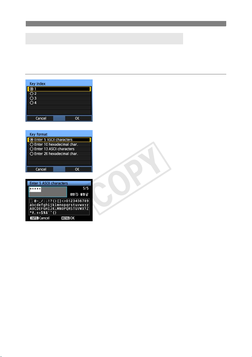
Entering the Wireless LAN Encryption Key
Enter the encryption key set for the wireless LAN terminal. For details on the encryption key,
refer to the device’s instruction manual.
Note that the screens displayed in steps 1 to 3 below vary depending on the authentication and
encryption of the wireless LAN terminal.
The [Key index] screen is displayed only if WEP
1
2
3
encryption is used by the wireless LAN terminal.
Turn the <5> dial to select the key index number
specified as the access point, and then press
<0>.
Select [OK] and press <0> to go to the next
screen.
Turn the <5> dial to select the key format, and
then press <0>.
Select [OK] and press <0> to go to the next
screen.
Enter the encryption key.
To switch between input areas, press the <Q>
button.
To move the cursor, turn the <5> dial.
In the bottom input area, turn the <5> dial and
press <0> to enter the encryption key.
If you make a mistake, press the <L> button to
erase it.
When you press the <7> button to complete
the connection with the wireless LAN terminal, the
[Network] screen (p.27) is displayed.
To return to the screen in step 2, press the
<6> button. The entry is canceled.
24
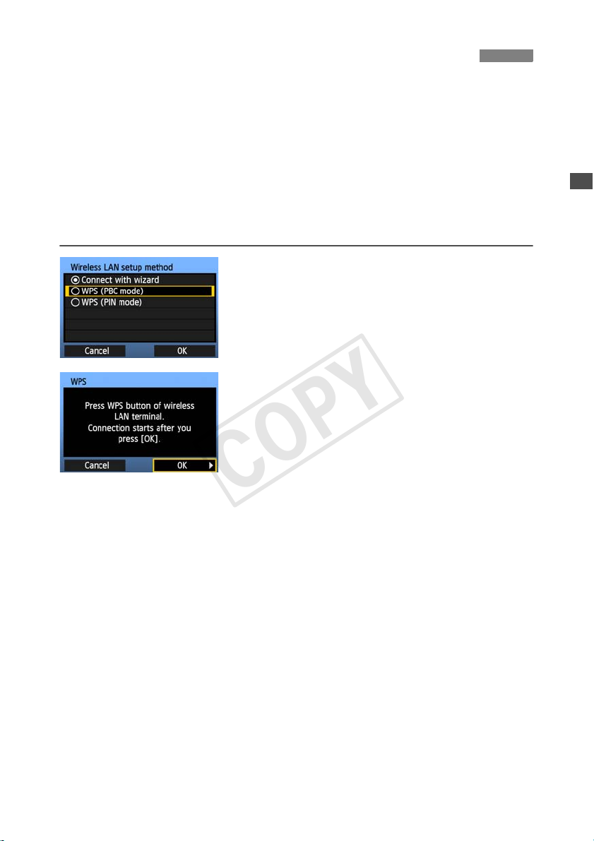
WPS Connections (PBC Mode)
COPY
This is a connection mode when using a wireless LAN terminal compatible with Wi-Fi Protected
Setup (WPS). Pushbutton Connection mode (PBC mode) makes it easy to establish a
connection between the camera and the wireless LAN terminal by pressing the WPS button on
the wireless LAN terminal.
Note that if multiple wireless LAN terminals are active in your area, it may be harder to establish
a connection. In this case, try using [WPS (PIN mode)] to establish a connection.
Confirm the position of the WPS button on the wireless LAN terminal in advance.
It may take about one minute to establish connection.
Connection may not be possible if stealth functions are enabled on the wireless LAN
terminal. Deactivate stealth functions.
Select [WPS (PBC mode)].
1
Turn the <5> dial to select [WPS (PBC mode)],
and then press <0>.
Select [OK] and press <0> to go to the next
screen.
Establish a connection with the
wireless LAN terminal.
2
Press the WPS button on the wireless LAN
terminal. For details about where the button is
located and how long to press it, refer to the
instruction manual of the wireless LAN terminal.
Select [OK] and press <0> to establish a
connection with the wireless LAN terminal.
When the connection with the wireless LAN
terminal is established, the [Network] screen
(p.27) is displayed.
25
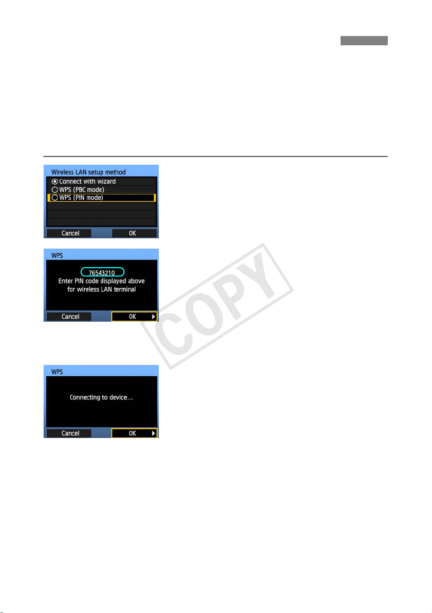
WPS Connections (PIN Mode)
COPY
This is a connection mode when using a wireless LAN terminal compatible with Wi-Fi Protected
Setup (WPS). In PIN code connection mode (PIN mode), an 8-digit identification number
specified on the camera is set on the wireless LAN terminal to establish a connection.
Even if there are multiple wireless LAN terminals active in your area, this is a relatively reliable
method of establishing a connection using a shared identification number.
It may take about one minute to establish connection.
Connection may not be possible if stealth functions are enabled on the wireless LAN
terminal. Deactivate stealth functions.
Select [WPS (PIN mode)].
1
Turn the <5> dial to select [WPS (PIN mode)],
and then press <0>.
Select [OK] and press <0> to go to the next
screen.
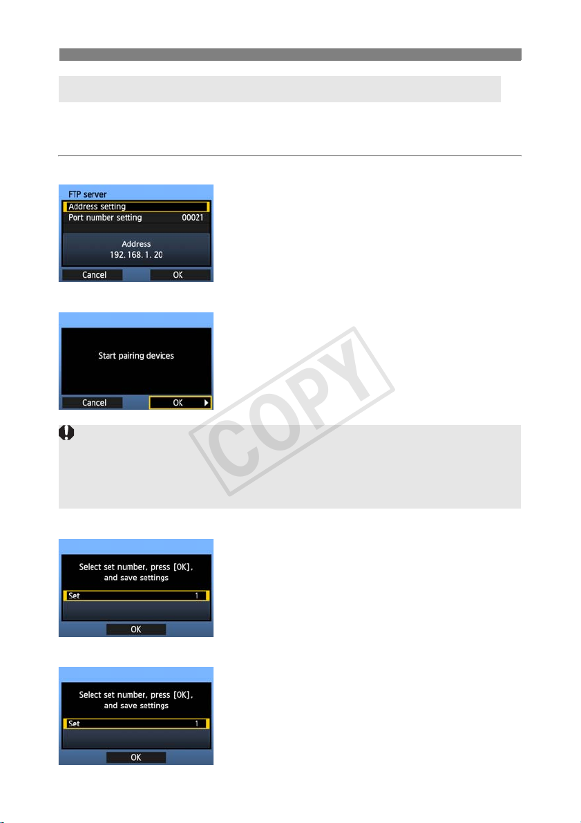
Specify the PIN code on the wireless
LAN terminal.
2
On the wireless LAN terminal, specify the 8-digit
PIN code shown on camera LCD monitor.
For instructions on setting PIN codes on the
wireless LAN terminal, refer to the instruction
manual of the wireless LAN terminal.
Select [OK] and press <0> to display the
confirmation screen.
Establish a connection with the
wireless LAN terminal.
3
Select [OK] and press <0> to establish a
connection with the wireless LAN terminal.
When the connection with the wireless LAN
terminal is established, the [Network] screen
(p.27) is displayed.
26
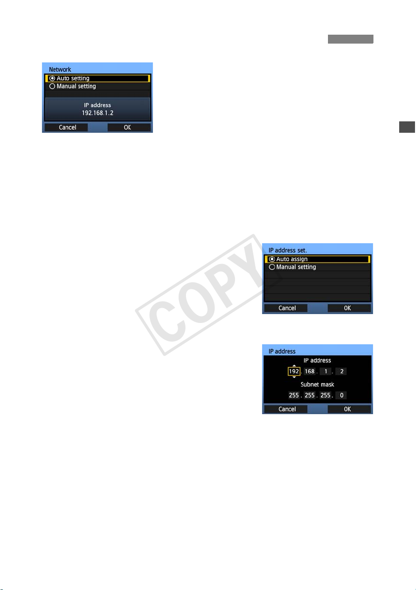
Configuring Network Settings
COPY
Turn the <5> dial to select a configuration
method for the network settings, and then press
<0>.
Select [OK] and press <0> to go to the next
screen.
[Auto setting]
Settings otherwise configured with [Manual setting] can be configured automatically.
However, the IP address and similar settings must be automatically assigned and
configured in environments using DHCP servers or wireless LAN terminals or routers
supporting DHCP server functions.
If an error is displayed, select [Manual setting] regardless of whether the IP address and
similar settings are automatically assigned and configured.
[Manual setting]
The [IP address set.] screen is displayed after you select
[Manual setting]. If [Auto setting] results in an error, select
[Manual setting]. The IP address you enter must be the IP
address assigned to the camera.
Enter the [IP address], [Subnet mask], [Gateway], and
[DNS address] on each screen as they are displayed.
If you are not sure what to enter, see page 112, “Checking
Network Settings,” or ask the network administrator or
another person knowledgeable about the network.
When entering numbers for the IP address, subnet mask,
and so on, press <0> to move the input position and turn
the <5> dial to enter the number.
27
Configuring Network Settings
COPY
Completing Settings for the Communication Method
The following instructions are for setting screens that vary depending on the communication
method (FTP Transfer, EOS Utility, WFT Server, or Media Server), as shown below. Read the
page that describes the selected communication method.
FTP trans.
Chapter 2 (p.31)
EOSUtility
Chapter 3 (p.47)
Windows 7 and Windows Vista Users
Before performing the operations described from page 47, perform the operations below. If these
operations are not performed, the WFT Pairing Software described on page 48 may not start.
Open the [C Drive] [Program Files] [Canon] [EOS Utility] [WFTPairing] folder (in this
order), and then double-click the [WFT FirewallSettings] icon.
After performing this operation, perform the operations described from page 47.
WFTserver
MediaServ.
28
Chapter 4 (p.53)
Chapter 5 (p.65)

Configuring Network Settings
COPY
Virtual Keyboard Operation
The virtual keyboard is displayed when entering the encryption key, server name, and other
information.
Switching between input areas
To switch between input areas, press the <Q>
button.
Moving the cursor
To move the cursor, turn the <5> dial.
You can also move the cursor using <9>.
Entering text
In the bottom input area, turn the <5> dial to move
the cursor and press <0> to enter text.
You can also move the cursor using <9>.
You can check how many characters you have
entered by referring to [*/5] in the upper-right corner of
the screen.
Deleting text
If you make a mistake, press the <L> button to erase
characters.
Confirming entries
Press the <7> button to confirm what you have
entered and go to the next screen.
Canceling entries
Press the <6> button to erase the entry and
return to the previous screen.
29

30
COPY
Loading...