


Installation Procedure
iR2020/2016 Series
Sep 14 2005
Application
This manual has been issued by Canon Inc. for qualified persons to learn technical theory, in- stallation, maintenance, and repair of products. This manual covers all localities where the prod- ucts are sold. For this reason, there may be information in this manual that does not apply to your locality.
Corrections
This manual may contain technical inaccuracies or typographical errors due to improvements or changes in products. When changes occur in applicable products or in the contents of this manual, Canon will release technical information as the need arises. In the event of major changes in the contents of this manual over a long or short period, Canon will issue a new edition of this manual.
The following paragraph does not apply to any countries where such provisions are inconsistent with local law.
Trademarks
The product names and company names used in this manual are the registered trademarks of the individual companies.
Copyright
This manual is copyrighted with all rights reserved. Under the copyright laws, this manual may not be copied, reproduced or translated into another language, in whole or in part, without the written consent of Canon Inc.
COPYRIGHT © 2001 CANON INC.
Printed in Japan
Caution
Use of this manual should be strictly supervised to avoid disclosure of confidential information.
Introduction
Symbols Used
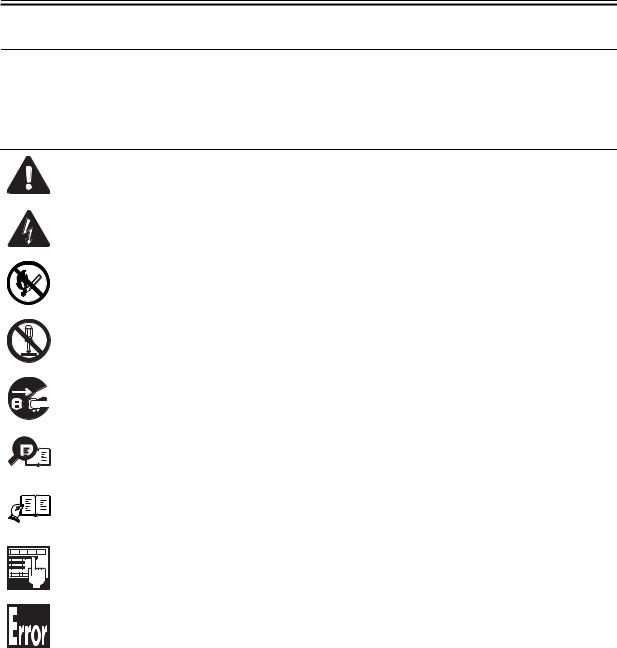
This documentation uses the following symbols to indicate special information:
Symbol Description
Indicates an item of a non-specific nature, possibly classified as Note, Caution, or Warning.
Indicates an item requiring care to avoid electric shocks.
Indicates an item requiring care to avoid combustion (fire).
Indicates an item prohibiting disassembly to avoid electric shocks or problems.
Indicates an item requiring disconnection of the power plug from the electric outlet.
Memo
REF.
Indicates an item intended to provide notes assisting the understanding of the topic in ques- tion.
Indicates an item of reference assisting the understanding of the topic in question.
Provides a description of a service mode.
Provides a description of the nature of an error indication.

Introduction
The following rules apply throughout this Service Manual:
1. Each chapter contains sections explaining the purpose of specific functions and the rela- tionship between electrical and mechanical systems with reference to the timing of operation.
In the |
diagrams, |
|
|
|
|
|
|
|
represents the path of mechanical drive; where a signal name accom- |
||
|
|
|
|
|
|
|
|||||
|
|
|
|
|
|
|
|||||
panies |
the symbol , the arrow |
|
indicates the direction of the electric signal. |
||||||||
|
|||||||||||
The expression "turn on the power" means flipping on the power switch, closing the front door, and closing the delivery unit door, which results in supplying the machine with power.
2. In the digital circuits, '1'is used to indicate that the voltage level of a given signal is "High", while '0' is used to indicate "Low".(The voltage value, however, differs from circuit to circuit.) In addition, the asterisk (*) as in "DRMD*" indicates that the DRMD signal goes on when '0'.
In practically all cases, the internal mechanisms of a microprocessor cannot be checked in the field. Therefore, the operations of the microprocessors used in the machines are not discussed: they are explained in terms of from sensors to the input of the DC controller PCB and from the output of the DC controller PCB to the loads.
The descriptions in this Service Manual are subject to change without notice for product im- provement or other purposes, and major changes will be communicated in the form of Service Information bulletins.
All service persons are expected to have a good understanding of the contents of this Service Manual and all relevant Service Information bulletins and be able to identify and isolate faults in the machine."

Contents
Contents
Chapter 1 Installation Procedure |
|
1.1 Making Pre-Checks ............................................................................................................................................ |
2 |
1.1.1Selecting the Site of Installation ................................................................................................................. |
2 |
1.1.2Before Starting the Work (230V EUR)....................................................................................................... |
3 |
1.2 Unpacking and Installation ................................................................................................................................ |
7 |
1.2.1Unpacking and Removing the Packaging Materials ............................................................................... |
7 |
1.2.2Installing the Drum Unit ............................................................................................................................... |
7 |
1.2.3Installing the Toner Bottle............................................................................................................................ |
9 |
1.2.4Setting the Cassettes ................................................................................................................................. |
10 |
1.2.5Attaching the Ferrite Core ......................................................................................................................... |
12 |
1.2.6Checking the Image Quality...................................................................................................................... |
13 |
1.2.7Setting the Country/Region ....................................................................................................................... |
13 |
1.2.8Setting the Date and Time......................................................................................................................... |
13 |
1.3 Checking the Connection to the Network ..................................................................................................... |
15 |
1.3.1Checking the Network Connection........................................................................................................... |
15 |
1.4 Installing the Card Reader............................................................................................................................... |
17 |
1.4.1Points to Note.............................................................................................................................................. |
17 |
1.4.2Checking the Contents............................................................................................................................... |
17 |
1.4.3Installation Procedure ................................................................................................................................ |
17 |
1.4.4Registering the Card IDs ........................................................................................................................... |
22 |
1.5 Installing the Heater PCB ................................................................................................................................ |
24 |
1.5.1Unpacking and Checking the Contents................................................................................................... |
24 |
1.5.2Preparing the Host Machine ..................................................................................................................... |
24 |
1.5.3Installing the Heater PCB .......................................................................................................................... |
25 |
1.6 Installing the Reader Heater ........................................................................................................................... |
29 |
1.6.1Unpacking and Checking the Contents................................................................................................... |
29 |
1.6.2Installing the Reader Heater Harness ..................................................................................................... |
29 |
1.6.3Removing Reader Components ............................................................................................................... |
32 |
1.6.4Removing Parts at the Left of the Reader .............................................................................................. |
33 |
1.6.5Installing the Reader Heater ..................................................................................................................... |
34 |
1.7 Installing the Cassette Heater......................................................................................................................... |
38 |
1.7.1Unpacking and Checking the Contents................................................................................................... |
38 |
1.7.2Preparing the Host Machine ..................................................................................................................... |
38 |
1.7.3Installing the Cassette Heater................................................................................................................... |
38 |

Contents

Chapter 1 Installation
Procedure
Chapter 1
1.1 Making Pre-Checks
1.1.1 Selecting the Site of Installation |
0011-1068 |
iR2016J / iR2016 / iR2020 / / iR2016i / iR2020i |
|
Select the site of installation against the following requirements; if possible, visit the user's before delivery of the machine:
1)There must be a power outlet properly grounded and rated as indicated (-/+10%) for exclusive use by the machine.
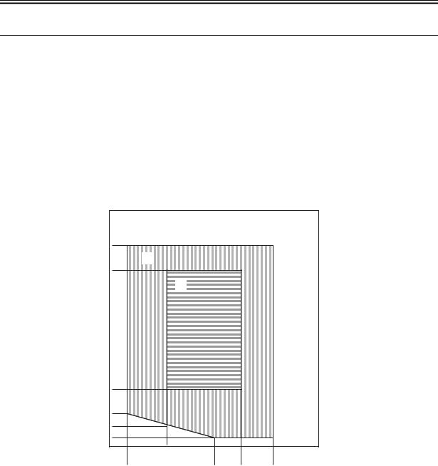
2)The environment of the room must be as indicated in the following diagram, and the machine must not be installed near a water faucet, water boiler, humidifier, or refrigerator:
(%RH) |
|
|
|
|
|
|
|
|
100 |
|
|
|
|
|
|
|
|
90 |
[C] |
|
|
|
|
|
|
|
|
|
|
|
|
|
|
|
|
85 |
|
[B] |
|
|
|
|
|
|
|
|
|
|
|
|
|
|
|
75 |
|
|
|
|
|
|
|
|
70 |
|
|
[A] |
|
|
|
|
|
50 |
|
|
|
|
|
|
|
|
25 |
|
|
|
|
|
|
|
|
20 |
|
|
|
|
|
|
|
|
15 |
|
|
|
|
|
|
|
|
10 |
|
|
|
|
|
|
|
|
5 |
|
|
|
|
|
|
|
|
0 |
10 |
15 |
20 |
25 |
30 |
35 |
40 |
(degC) |
|
7.5 |
|
|
23 |
27.5 |
32.5 |
|
|
|
|
|
|
F-1-1 |
|
|
|
|
<Environmental zone assured> |
|
|
|
|
|
|
|
|
[A]: Zone A: Satisfies all the conditions of the standard image quality and paper feed performance.
[B]: Zone B: Inferior to Zone A in terms of the standard image quality and paper feed performance, or may not apply. [C]: Zone C: Problems associated with safety, malfunctions, or incorrect message display do not occur, but image
quality and paper feed performance are not guaranteed.
3)The machine must not be installed near a source of fire or in an area subject to dust or ammonium gas. If the area is exposed to direct rays of the sun, provide curtains to the window.
4)The level of ozone generated by the machine will not affect the health of individuals around it. Some, however, may find its odor unpleasant as while remaining in contact with it for long hours. Be sure that the room is well
2
Chapter 1
ventilated.
5)The floor of the machine must be level so that the feet of the machine will remain in contact and the machine will remain level.
6)The machine must be at least 10 cm away from any wall, permitting unobstructed use.
|
100 mm min. |
1249 mm |
.min mm 100 |
1247 mm
F-1-2
7)The machine must be placed in a well ventilated area. It is important to make sure, however, that the machine is not near the air vent (for suction) of the room.
1.1.2 Before Starting the Work (230V EUR) |
0011-3206 |
iR2016J / iR2016 / iR2020 |
|
1-1 Points to Make Before Installation
Be sure to go through the following before starting the work:
1)If you are installing the machine after moving it from a cold to warm location, be sure to leave the machine unpacked for at least 2 hours so that the machine is fully used to the site temperature, thus avoiding image faults caused by condensation. (The term "condensation" refers to the formation of droplets of water on the surface of a metal object brought in from a cold to warm place, i.e., as the result of the rapid cooling of the moisture (vapor) around the object.)
2)The machine weighs a maximum of about 46 kg. Be sure to work in a group of 2 persons when lifting it.
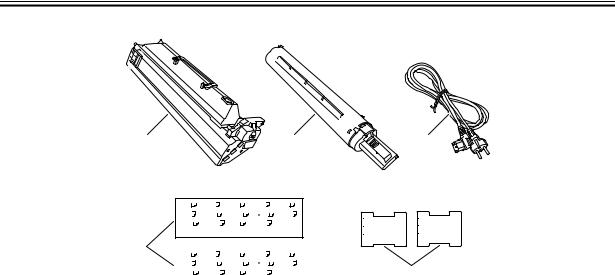
1-2 Checking the Contents
Check to be sure that none of the following contents is missing:
3
Chapter 1
[1] |
[2] |
A3 |
|
|
|
|
|
A4 |
|
|
A4 |
|
|
|
|
|
A5 |
|
|
|
B4 |
|
|
|
|||||
B5 |
|
|
|
B5 |
|
|
|
LGL |
|
|
11 17 |
|
|
|
LTR |
|
|
||||||||||
LTR |
|
|
STMT |
|
|
8K |
|
|
|
|
16K |
|
|
|
|
|
|
|
|||||||||
|
|
|
|
|
|
|
|
|
|
|
|
|
|||||||||||||||
|
|
|
|
|
|
|
|
|
|
||||||||||||||||||
[4] |
|
|
|
|
|
|
|
|
|
|
|
|
|
|
|
|
|
|
|
|
|
|
|
|
|
|
|
|
A3 |
|
|
|
|
|
A4 |
|
A4 |
|
|
|
|
|
A5 |
|
|
B4 |
|
|
|
|
|||||
|
B5 |
|
|
|
B5 |
|
|
|
LGL |
|
|
11 17 |
|
|
|
LTR |
|
|
|||||||||
|
LTR |
|
|
STMT |
|
|
8K |
|
|
|
|
16K |
|
|
|
|
|
|
|
|
|||||||
|
|
|
|
|
|
|
|
|
|
|
|
|
|
|
|||||||||||||
|
|
|
|
|
|
|
|
|
|
|
|
||||||||||||||||
|
|
|
|
|
|
|
|
|
|
|
|
|
|
|
|
|
|
|
|
|
|
|
|
|
|
|
|
[3]
Set the size detector lever to the |
Set the size detector lever to the |
new paper size. |
new paper size. |
Placer I’indicateur de format sur |
Placer I’indicateur de format sur |
le nouveau format. |
le nouveau format. |
Bitte stellen Sie den Hebel zum |
Bitte stellen Sie den Hebel zum |
Erkennen des Papierformats auf |
Erkennen des Papierformats auf |
das neue Format ein. |
das neue Format ein. |
FU5-xxxx |
FU5-xxxx |
[5]
F-1-3
[1] |
Drum unit |
---1 |
[4] |
Cassette size label |
---2(1) |
(*1) |
[2] |
Black toner |
---1 |
[5] |
Caution sheet |
---2(1) |
(*1) |
[3] |
Power cable |
---1 |
|
|
|
|
*1: iR2020: 2 pc., iR2016/iR2016J: 1 pc.
Check the documentation and CD against the following table:
T-1-1
Documentation and CD |
iR2020/iR2016 |
iR2016J |
|
|
|
Operators manual: User's Guide |
Yes |
Yes |
|
|
|
Operators manual: Easy Operation Guide |
No |
Yes |
|
|
|
Operators manual CD-ROM |
Yes |
Yes |
|
|
|
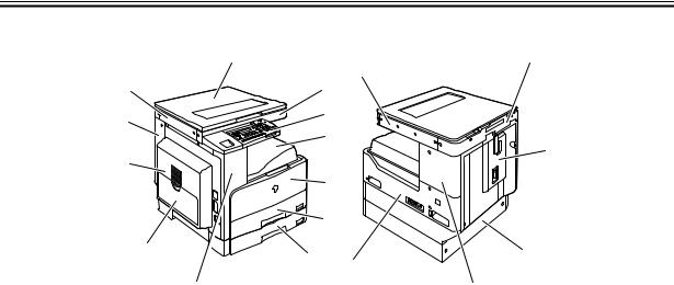
1-3 Names of Parts
4
Chapter 1
|
|
[1] |
|
[13] |
|
|
|
|
|
|
|
|
[12] |
|
|
[2] |
|
|
[11] |
|
|
[3] |
|
|
|
|
[4] |
|
|
|
|
|
|
|
|
|
[10] |
|
|
|
|
|
|
|
|
[5] |
|
|
|
|
|
[6] |
|
|
[9] |
|
[7] |
[18] |
|
|
|
|
|
||
|
|
|
|
|
|
|
[8] |
|
|
|
[17] |
|
|
|
F-1-4 |
|
|
|
|
|
T-1-2 |
|
|
[1] |
Copyboard cover |
|
|
[10] |
Left door |
[2] |
Reader front cover |
|
|
[11] |
Left cover (rear) |
[3] |
Control panel |
|
|
[12] |
Reader left cover |
[4] |
Delivery tray |
|
|
[13] |
Reader right cover |
[5] |
Front cover |
|
|
[14] |
Reader erar cover |
[6] |
Cassette 1 |
|
|
[15] |
Rear cover |
[7] |
Cassette 2 |
(*2) |
|
[16] |
Cassette rear cover |
[8] |
Left cover (front) |
|
|
[17] |
Right cover (upper) |
[9] |
Manual feed tray |
|
|
[18] |
Right cover (lower) |
*2. iR2020 only
[14]
[15]
[16]
(*2)
5

Chapter 1
6
Chapter 1
1.2 Unpacking and Instal-
lation
1.2.1 Unpacking |
and |
Removing the Packag- |
|
ing Materials |
0011-1070 |
iR2016J / iR2016 / iR2020 / / iR2016i / iR2020i
1)Unpack the machine and remove vinyl, cushioning materials, and tape.
2)Hold the handles [1] of the machine together with one or more persons and take it out.
The maximum weight of this machine is approximately 46kg. Two or more persons are required to lift the machine.
[1]
|
[1] |
F-1-5 |
|
1.2.2 Installing the Drum |
|
Unit |
0011-1071 |
iR2016J / iR2016 / iR2020 / / iR2016i / iR2020i
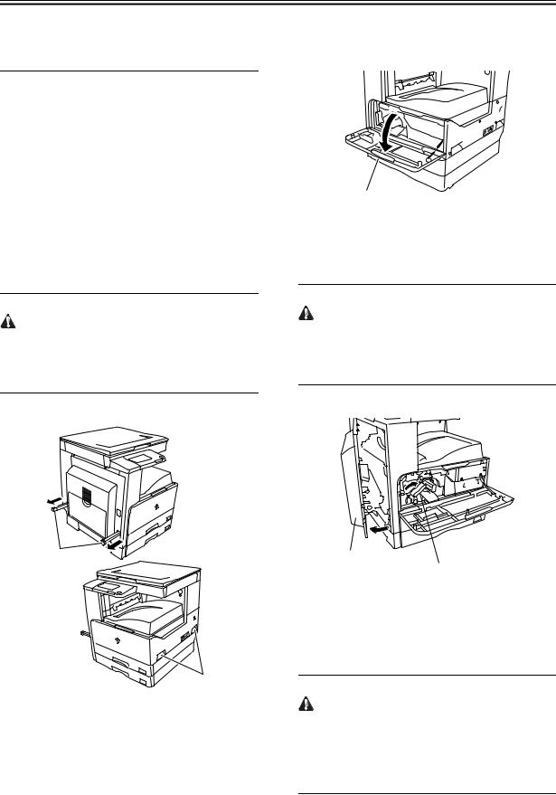
1) Open the front cover [1] of the iR body.
[1]
F-1-6
2)Turn the developer pressure release lever [1] clockwise, and then open the left door [2] until it stops.
The left door must be opened fully to prevent the drum from being damaged while it is inserted into the drum unit.
[2]
[1]
F-1-7
3)Open the packaging bag of the new drum unit, take the new drum out of it, and then remove packing tape.
The drum unit for Asia/Oceania is provided with pressure release hooks [1]. Remove them. Drum units for other regions are not provided with the pressure release hooks.
7

Chapter 1
[1]
F-1-8
4) Holding the protective cover [1] of the new drum unit, place the drum unit against the iR body.
[1]
F-1-9
5) While holding the protective cover, insert the new drum unit [1] into the iR body.
MEMO:
The protective cover will not be reused.
[1]
F-1-10
6)Turn the developer pressure release lever [1] counterclockwise, and then close the left door [2].
[2]
[1]
F-1-11
7) Enter the date in the drum counter label [1].
[1]
F-1-12 |
8) Affix the drum counter label [1] on the drum unit.
[1]
F-1-13
9) Close the front cover [1].
8
 Loading...