


 Loading...
Service Manual
Duplex unit
Duplex Unit-A1
Sep 14 2005
Application
This manual has been issued by Canon Inc. for qualified persons to learn technical theory, installation, maintenance, and repair of products. This manual covers all localities where the products are sold. For this reason, there may be information in this manual that does not apply to your locality.
Corrections
This manual may contain technical inaccuracies or typographical errors due to improvements or changes in products. When changes occur in applicable products or in the contents of this manual, Canon will release technical information as the need arises. In the event of major changes in the contents of this manual over a long or short period, Canon will issue a new edition of this manual.
The following paragraph does not apply to any countries where such provisions are inconsistent with local law.
Trademarks
The product names and company names used in this manual are the registered trademarks of the individual companies.
Copyright
This manual is copyrighted with all rights reserved. Under the copyright laws, this manual may not be copied, reproduced or translated into another language, in whole or in part, without the written consent of Canon Inc.
COPYRIGHT © 2001 CANON INC.
Printed in Japan
Caution
Use of this manual should be strictly supervised to avoid disclosure of confidential information.
Introduction
Symbols Used
This documentation uses the following symbols to indicate special information:
Symbol Description
Indicates an item of a non-specific nature, possibly classified as Note, Caution, or Warning.
Indicates an item requiring care to avoid electric shocks.
Indicates an item requiring care to avoid combustion (fire).
Indicates an item prohibiting disassembly to avoid electric shocks or problems.
Indicates an item requiring disconnection of the power plug from the electric outlet.
Indicates an item intended to provide notes assisting the understanding of the topic in question.
Memo
Indicates an item of reference assisting the understanding of the topic in question.
REF.
Provides a description of a service mode.
Provides a description of the nature of an error indication.

Introduction
The following rules apply throughout this Service Manual:
1.Each chapter contains sections explaining the purpose of specific functions and the relationship between electrical and mechanical systems with reference to the timing of operation.
In the diagrams,  represents the path of mechanical drive; where a signal name accompanies the symbol , the arrow
  indicates the
direction of the electric signal.
The expression "turn on the power" means flipping on the power switch, closing the front door, and closing the delivery unit door, which results in supplying the machine with power.
2.In the digital circuits, '1'is used to indicate that the voltage level of a given signal is "High", while '0' is used to indicate "Low".(The voltage value, however, differs from circuit to circuit.) In addition, the asterisk (*) as in "DRMD*" indicates that the DRMD signal goes on when '0'.
In practically all cases, the internal mechanisms of a microprocessor cannot be checked in the field. Therefore, the operations of the microprocessors used in the machines are not discussed: they are explained in terms of from sensors to the input of the DC controller PCB and from the output of the DC controller PCB to the loads.
The descriptions in this Service Manual are subject to change without notice for product improvement or other purposes, and major changes will be communicated in the form of Service Information bulletins.
All service persons are expected to have a good understanding of the contents of this Service Manual and all relevant Service Information bulletins and be able to identify and isolate faults in the machine."

Contents
Contents
Chapter 1 Specifications
1.1 |
Product Specifications ................................................................................................................................... |
1- 1 |
1.1.1 Specifications ........................................................................................................................................... |
1- 1 |
|
1.2 |
Names of Parts ............................................................................................................................................... |
1- 1 |
1.2.1 External View............................................................................................................................................ |
1- 1 |
|
1.2.2 Sectional View.......................................................................................................................................... |
1- 2 |
|
Chapter 2 Functions
2.1 Basic Construction.......................................................................................................................................... |
2- 1 |
2.1.1 Outline ....................................................................................................................................................... |
2- 1 |
2.2 Pick-Up/Feed Systm....................................................................................................................................... |
2- 1 |
2.2.1 Outline ....................................................................................................................................................... |
2- 1 |
2.2.2 Paper Feed Path...................................................................................................................................... |
2- 3 |
2.2.3 Paper Feed Operation ............................................................................................................................ |
2- 3 |
2.3 Detecting Jams ............................................................................................................................................. |
2- 10 |
2.3.1 Outline ..................................................................................................................................................... |
2- 10 |
2.3.2 Delay Jam ............................................................................................................................................... |
2- 10 |
2.3.3 Stationary Jam ....................................................................................................................................... |
2- 10 |
Chapter 3 Parts Replacement Procedure
3.1 Removing from the Host Machine................................................................................................................ |
3- 1 |
3.1.1 Duplex Unit................................................................................................................................................ |
3- 1 |
3.1.1.1 Removing the Drum Unit ................................................................................................................. |
3- 1 |
3.1.1.2 Removing the Rear Cover............................................................................................................... |
3- 1 |
3.1.1.3 Removing the Left Cover (Rear) .................................................................................................... |
3- 1 |
3.1.1.4 Removing the Duplex Unit............................................................................................................... |
3- 1 |
3.2 Drive System ................................................................................................................................................... |
3- 2 |
3.2.1 Reversal Motor ......................................................................................................................................... |
3- 2 |
3.2.1.1 Removing the Reversal Motor ........................................................................................................ |
3- 2 |
3.2.2 Feed Motor ................................................................................................................................................ |
3- 2 |
3.2.2.1 Removing the Feed Motor............................................................................................................... |
3- 2 |
3.3 Electrical System ............................................................................................................................................ |
3- 2 |
3.3.1 Duplex Paper Sensor............................................................................................................................... |
3- 2 |
3.3.1.1 Removing the Duplex Paper Sensor ............................................................................................. |
3- 2 |
3.3.2 Duplex Flapper Solenoid......................................................................................................................... |
3- 2 |
3.3.2.1 Removing the Duplex Flapper Solenoid ....................................................................................... |
3- 2 |
3.3.3 Duplex Controller PCB ............................................................................................................................ |
3- 3 |
3.3.3.1 Removing the Duplex Controller PCB ........................................................................................... |
3- 3 |
Chapter 4 Maintenance

Contents
4.1 Maintenance and Inspection ......................................................................................................................... |
4- 1 |
4.1.1 Periodically Replaced Parts .................................................................................................................... |
4- 1 |
4.1.1.1 Periodically Replaced Parts ............................................................................................................ |
4- 1 |
4.1.2 Durables..................................................................................................................................................... |
4- 1 |
4.1.2.1 Durables ............................................................................................................................................. |
4- 1 |
4.1.3 Periodical Servicing.................................................................................................................................. |
4- 1 |
4.1.3.1 Periodical Servicing Items ............................................................................................................... |
4- 1 |
4.2 Outline of Electrical Components ................................................................................................................. |
4- 1 |
4.2.1 Outline of Electrical Components .......................................................................................................... |
4- 1 |
Chapter 5 Error Code
5.1 |
Service Error Code ......................................................................................................................................... |
5- 1 |
5.1.1 Error Code list........................................................................................................................................... |
5- 1 |
|
5.2 |
Jam Codes ....................................................................................................................................................... |
5- 1 |
5.2.1 Jam Code List........................................................................................................................................... |
5- 1 |
|

Chapter 1 Specifications
Contents
Contents
1.1 |
Product Specifications........................................................................................................................................ |
1-1 |
1.1.1 Specifications .............................................................................................................................................. |
1-1 |
|
1.2 |
Names of Parts.................................................................................................................................................... |
1-1 |
1.2.1 External View.............................................................................................................................................. |
1-1 |
|
1.2.2 Sectional View ............................................................................................................................................ |
1-2 |
|

Chapter 1
1.1 Product Specifications
1.1.1 Specifications
|
|
T-1-1 |
|
|
|
Item |
Description |
Remarks |
|
|
|
|
|
|
|
Type |
Built in the host machine |
|
|
|
Paper supply method |
Switchback reversing method |
|
|
|
Copy paper type |
60g/m2 to 90g/m2 |
|
|
|
Copy paper size |
A3, B4, A4, A4R, B5, B5R, A5R, 11X17, LGL, LTR, |
|
|
|
|
LTR-R, STMTR |
|
|
|
Power supply |
DC power supply from host machine |
|
|
|
Weight |
2.5 kg |
|
|
|
Dimensions |
437.2 mm x 448 mm x 378.3 mm (W x D x H) |
Incl. reversal tray dimensions |
|
1.2 Names of Parts |
|
|
|
|
1.2.1 External View |
|
|
|
|
[2]
[3]
[1]
[4]
[5]
|
F-1-1 |
|
T-1-2 |
[1] Duplex unit |
[4] Blind cover |
[2] Reversal tray |
[5] Reversal guide |
[3] Reversal tray (sub) |
|
1-1
Chapter 1
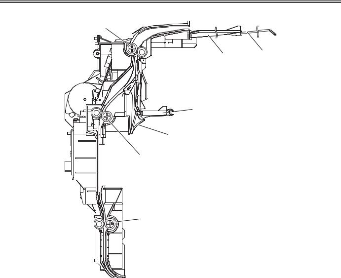
1.2.2 Sectional View
[1]
[2]
[3]
 [4]
[4]
[5]
[6]
[7]
[8]
|
F-1-2 |
|
T-1-3 |
[1] Feed roller 1 |
[5] Delivery guide |
[2] Reversal tray (sub) |
[6] Duplex flapper |
[3] Reversal tray |
[7] Feed roller 2 |
[4] Reversal flapper |
[8] Feed roller 3 |
1-2

Chapter 2 Functions
Loading...