


 Loading...
Service Manual
Feeder
DADF-P1
Sep 14 2005
Application
This manual has been issued by Canon Inc. for qualified persons to learn technical theory, installation, maintenance, and repair of products. This manual covers all localities where the products are sold. For this reason, there may be information in this manual that does not apply to your locality.
Corrections
This manual may contain technical inaccuracies or typographical errors due to improvements or changes in products. When changes occur in applicable products or in the contents of this manual, Canon will release technical information as the need arises. In the event of major changes in the contents of this manual over a long or short period, Canon will issue a new edition of this manual.
The following paragraph does not apply to any countries where such provisions are inconsistent with local law.
Trademarks
The product names and company names used in this manual are the registered trademarks of the individual companies.
Copyright
This manual is copyrighted with all rights reserved. Under the copyright laws, this manual may not be copied, reproduced or translated into another language, in whole or in part, without the written consent of Canon Inc.
COPYRIGHT © 2001 CANON INC.
Printed in Japan
Caution
Use of this manual should be strictly supervised to avoid disclosure of confidential information.
Introduction
Symbols Used
This documentation uses the following symbols to indicate special information:
Symbol Description
Indicates an item of a non-specific nature, possibly classified as Note, Caution, or Warning.
Indicates an item requiring care to avoid electric shocks.
Indicates an item requiring care to avoid combustion (fire).
Indicates an item prohibiting disassembly to avoid electric shocks or problems.
Indicates an item requiring disconnection of the power plug from the electric outlet.
Indicates an item intended to provide notes assisting the understanding of the topic in question.
Memo
Indicates an item of reference assisting the understanding of the topic in question.
REF.
Provides a description of a service mode.
Provides a description of the nature of an error indication.

Introduction
The following rules apply throughout this Service Manual:
1.Each chapter contains sections explaining the purpose of specific functions and the relationship between electrical and mechanical systems with reference to the timing of operation.
In the diagrams,  represents the path of mechanical drive; where a signal name accompanies the symbol , the arrow
  indicates the
direction of the electric signal.
The expression "turn on the power" means flipping on the power switch, closing the front door, and closing the delivery unit door, which results in supplying the machine with power.
2.In the digital circuits, '1'is used to indicate that the voltage level of a given signal is "High", while '0' is used to indicate "Low".(The voltage value, however, differs from circuit to circuit.) In addition, the asterisk (*) as in "DRMD*" indicates that the DRMD signal goes on when '0'.
In practically all cases, the internal mechanisms of a microprocessor cannot be checked in the field. Therefore, the operations of the microprocessors used in the machines are not discussed: they are explained in terms of from sensors to the input of the DC controller PCB and from the output of the DC controller PCB to the loads.
The descriptions in this Service Manual are subject to change without notice for product improvement or other purposes, and major changes will be communicated in the form of Service Information bulletins.
All service persons are expected to have a good understanding of the contents of this Service Manual and all relevant Service Information bulletins and be able to identify and isolate faults in the machine."

Contents
Contents
Chapter 1 Specifications
1.1 |
Product Specifications ................................................................................................................................... |
1- 1 |
1.1.1 Specifications ........................................................................................................................................... |
1- 1 |
|
1.2 |
Names of Parts ............................................................................................................................................... |
1- 2 |
1.2.1 External View............................................................................................................................................ |
1- 2 |
|
1.2.2 Cross-section............................................................................................................................................ |
1- 2 |
|
Chapter 2 Functions
2.1 |
Basic Construction.......................................................................................................................................... |
2- 1 |
2.1.1 Outline of Electric Circuit ........................................................................................................................ |
2- 1 |
|
2.2 |
Basic Operation............................................................................................................................................... |
2- 1 |
2.2.1 Drive Mechanism and Signals ............................................................................................................... |
2- 1 |
|
2.2.2 Outline of Operation Mode ..................................................................................................................... |
2- 2 |
|
2.2.3 Forward Pickup/Delivery (Single-sided document > Simplex Printing) Operation ........................ |
2- 2 |
|
2.2.4 Forward Pickup/Reversal Delivery (Double-sided document > Duplex printing) Operation........ |
2- 2 |
|
2.3 |
Document Detection....................................................................................................................................... |
2- 4 |
2.3.1 Outline ....................................................................................................................................................... |
2- 4 |
|
2.3.2 Document Presence/Absence Detection ............................................................................................. |
2- 4 |
|
2.3.3 Detection of Last Document................................................................................................................... |
2- 4 |
|
2.3.4 Initial Document Size Detection ............................................................................................................ |
2- 5 |
|
2.4 |
Document Pickup/Separation ....................................................................................................................... |
2- 6 |
2.4.1 Basic Pickup Operation .......................................................................................................................... |
2- 6 |
|
2.4.2 Pickup Unit and Stopper......................................................................................................................... |
2- 7 |
|
2.4.3 Pickup Timing........................................................................................................................................... |
2- 7 |
|
2.4.4 Pickup Motor (M2) Control ..................................................................................................................... |
2- 7 |
|
2.5 |
Document Reversing...................................................................................................................................... |
2- 8 |
2.5.1 Basic Operation........................................................................................................................................ |
2- 8 |
|
2.5.2 Operation Sequence ............................................................................................................................... |
2- 9 |
|
2.6 |
Document Feeding/Delivery.......................................................................................................................... |
2- 9 |
2.6.1 Basic Operation........................................................................................................................................ |
2- 9 |
|
2.6.2 Operation Sequence ............................................................................................................................. |
2- 10 |
|
2.6.3 Feed Motor (M1) Control ...................................................................................................................... |
2- 10 |
|
2.7 |
Detecting Jams ............................................................................................................................................. |
2- 10 |
2.7.1 Jam .......................................................................................................................................................... |
2- 10 |
|
2.8 |
Power Supply ................................................................................................................................................ |
2- 11 |
2.8.1 Power Supply ......................................................................................................................................... |
2- 11 |
|
2.9 |
Stamp Operation........................................................................................................................................... |
2- 11 |
2.9.1 Outline ..................................................................................................................................................... |
2- 11 |
|
Chapter 3 Parts Replacement Procedure
3.1 Removing from the Host Machine................................................................................................................ |
3- 1 |

Contents
3.1.1 Feeder ........................................................................................................................................................ |
3- 1 |
3.1.1.1 Removing from the Host Machine .................................................................................................. |
3- 1 |
3.2 External Covers............................................................................................................................................... |
3- 1 |
3.2.1 Front Cover................................................................................................................................................ |
3- 1 |
3.2.1.1 Removing the Front Cover .............................................................................................................. |
3- 1 |
3.2.2 Rear Cover ................................................................................................................................................ |
3- 1 |
3.2.2.1 Removing the Rear Cover ............................................................................................................... |
3- 1 |
3.2.3 Feeder Cover ............................................................................................................................................ |
3- 1 |
3.2.3.1 Removing the Front Cover .............................................................................................................. |
3- 1 |
3.2.3.2 Removing the Feeder Cover ........................................................................................................... |
3- 2 |
3.3 Drive System.................................................................................................................................................... |
3- 2 |
3.3.1 Pickup Motor.............................................................................................................................................. |
3- 2 |
3.3.1.1 Removing the Rear Cover ............................................................................................................... |
3- 2 |
3.3.1.2 Removing the Pickup Motor ............................................................................................................ |
3- 2 |
3.3.1.3 Installing the Pickup Motor .............................................................................................................. |
3- 2 |
3.3.2 Feed Motor ................................................................................................................................................ |
3- 3 |
3.3.2.1 Removing the Rear Cover ............................................................................................................... |
3- 3 |
3.3.2.2 Removing the Feed Motor ............................................................................................................... |
3- 3 |
3.3.2.3 Installing the Feed Motor ................................................................................................................. |
3- 3 |
3.3.3 Timing Belt/Pulley..................................................................................................................................... |
3- 3 |
3.3.3.1 Removing the Front Cover .............................................................................................................. |
3- 3 |
3.3.3.2 Removing the Feeder Cover ........................................................................................................... |
3- 3 |
3.3.3.3 Removing the Rear Cover ............................................................................................................... |
3- 4 |
3.3.3.4 Removing the ADF Driver PCB ...................................................................................................... |
3- 4 |
3.3.3.5 Removing the Pickup Motor ............................................................................................................ |
3- 4 |
3.3.3.6 Removing the Feed Motor ............................................................................................................... |
3- 4 |
3.3.3.7 Removing the Timing Belt................................................................................................................ |
3- 4 |
3.4 Document Feeding System ........................................................................................................................... |
3- 5 |
3.4.1 Pickup Roller Unit ..................................................................................................................................... |
3- 5 |
3.4.1.1 Removing the Front Cover .............................................................................................................. |
3- 5 |
3.4.1.2 Removing the Feeder Cover ........................................................................................................... |
3- 5 |
3.4.1.3 Removing the Pickup Roller Unit.................................................................................................... |
3- 5 |
3.4.1.4 Precaution about Pickup Roller Unit Installation ......................................................................... |
3- 6 |
3.4.2 Pickup Roller/Separation Roller ............................................................................................................. |
3- 6 |
3.4.2.1 Removing the Front Cover .............................................................................................................. |
3- 6 |
3.4.2.2 Removing the Feeder Cover ........................................................................................................... |
3- 6 |
3.4.2.3 Removing the Pickup Roller Unit.................................................................................................... |
3- 6 |
3.4.2.4 Removing the Pickup Roller and Separation Roller .................................................................... |
3- 6 |
3.4.3 Separation Plate/Separation Pad........................................................................................................... |
3- 7 |
3.4.3.1 Removing the Separation Pad ........................................................................................................ |
3- 7 |
3.4.4 Upper Registration Roller ........................................................................................................................ |
3- 7 |
3.4.4.1 Removing the Front Cover .............................................................................................................. |
3- 7 |
3.4.4.2 Removing the Feeder Cover ........................................................................................................... |
3- 7 |
3.4.4.3 Removing the Upper Registration Roller....................................................................................... |
3- 7 |
3.4.5 Lower Registration Roller ........................................................................................................................ |
3- 8 |
3.4.5.1 Removing the Front Cover .............................................................................................................. |
3- 8 |
3.4.5.2 Removing the Feeder Cover ........................................................................................................... |
3- 8 |
3.4.5.3 Removing the Rear Cover ............................................................................................................... |
3- 8 |
3.4.5.4 Removing the ADF Driver PCB ...................................................................................................... |
3- 8 |
|
Contents |
|
|
|
|
3.4.5.5 Removing the Feed Motor............................................................................................................... |
3- 8 |
3.4.5.6 Removing the Timing Belt ............................................................................................................... |
3- 9 |
3.4.5.7 Removing the Document Tray........................................................................................................ |
3- 9 |
3.4.5.8 Removing the Feeding Unit............................................................................................................. |
3- 9 |
3.4.5.9 Removing the Platen Roller Unit .................................................................................................... |
3- 9 |
3.4.5.10 Removing the Read Roller 2....................................................................................................... |
3- 10 |
3.4.5.11 Removing the Sensor Unit in the Feeder Unit ......................................................................... |
3- 10 |
3.4.5.12 Removing the Lower Registration Roller .................................................................................. |
3- 10 |
3.4.6 Delivery Reversing Roller (upper) ....................................................................................................... |
3- 11 |
3.4.6.1 Removing the Front Cover ............................................................................................................ |
3- 11 |
3.4.6.2 Removing the Feeder Cover......................................................................................................... |
3- 11 |
3.4.6.3 Removing the Rear Cover............................................................................................................. |
3- 11 |
3.4.6.4 Removing the ADF Driver PCB .................................................................................................... |
3- 11 |
3.4.6.5 Removing the Pickup Motor.......................................................................................................... |
3- 11 |
3.4.6.6 Removing the Feed Motor............................................................................................................. |
3- 12 |
3.4.6.7 Removing the Timing Belt ............................................................................................................. |
3- 12 |
3.4.6.8 Removing the Document Tray...................................................................................................... |
3- 12 |
3.4.6.9 Removing the Feeding Unit........................................................................................................... |
3- 13 |
3.4.6.10 Removing the Upper Delivery Reversing Roller ...................................................................... |
3- 13 |
3.4.7 Read Roller 1 .......................................................................................................................................... |
3- 13 |
3.4.7.1 Removing the Front Cover ............................................................................................................ |
3- 13 |
3.4.7.2 Removing the Feeder Cover......................................................................................................... |
3- 13 |
3.4.7.3 Removing the Rear Cover............................................................................................................. |
3- 14 |
3.4.7.4 Removing the ADF Driver PCB .................................................................................................... |
3- 14 |
3.4.7.5 Removing the Pickup Motor.......................................................................................................... |
3- 14 |
3.4.7.6 Removing the Feed Motor............................................................................................................. |
3- 14 |
3.4.7.7 Removing the Timing Belt ............................................................................................................. |
3- 14 |
3.4.7.8 Removing the Document Tray...................................................................................................... |
3- 15 |
3.4.7.9 Removing the Feeding Unit........................................................................................................... |
3- 15 |
3.4.7.10 Removing the Read Roller 1....................................................................................................... |
3- 15 |
3.4.8 Read Roller 2 .......................................................................................................................................... |
3- 16 |
3.4.8.1 Removing the Front Cover ............................................................................................................ |
3- 16 |
3.4.8.2 Removing the Feeder Cover......................................................................................................... |
3- 16 |
3.4.8.3 Removing the Rear Cover............................................................................................................. |
3- 16 |
3.4.8.4 Removing the ADF Driver PCB .................................................................................................... |
3- 16 |
3.4.8.5 Removing the Pickup Motor.......................................................................................................... |
3- 16 |
3.4.8.6 Removing the Feed Motor............................................................................................................. |
3- 17 |
3.4.8.7 Removing the Timing Belt ............................................................................................................. |
3- 17 |
3.4.8.8 Removing the Document Tray...................................................................................................... |
3- 17 |
3.4.8.9 Removing the Feeding Unit........................................................................................................... |
3- 18 |
3.4.8.10 Removing the Read Roller 2....................................................................................................... |
3- 18 |
3.4.9 Platen Roller............................................................................................................................................ |
3- 18 |
3.4.9.1 Removing the Front Cover ............................................................................................................ |
3- 18 |
3.4.9.2 Removing the Feeder Cover......................................................................................................... |
3- 19 |
3.4.9.3 Removing the Rear Cover............................................................................................................. |
3- 19 |
3.4.9.4 Removing the ADF Driver PCB .................................................................................................... |
3- 19 |
3.4.9.5 Removing the Pickup Motor.......................................................................................................... |
3- 19 |
3.4.9.6 Removing the Feed Motor............................................................................................................. |
3- 19 |
3.4.9.7 Removing the Timing Belt ............................................................................................................. |
3- 19 |

Contents
3.4.9.8 Removing the Document Tray ...................................................................................................... |
3- 20 |
3.4.9.9 Removing the Feeding Unit........................................................................................................... |
3- 20 |
3.4.9.10 Removing the Platen Roller......................................................................................................... |
3- 20 |
3.4.10 Delivery Reversing Roller (lower) ...................................................................................................... |
3- 21 |
3.4.10.1 Removing the Front Cover .......................................................................................................... |
3- 21 |
3.4.10.2 Removing the Feeder Cover ....................................................................................................... |
3- 21 |
3.4.10.3 Removing the Rear Cover ........................................................................................................... |
3- 21 |
3.4.10.4 Removing the ADF Driver PCB .................................................................................................. |
3- 21 |
3.4.10.5 Removing the Pickup Motor ........................................................................................................ |
3- 22 |
3.4.10.6 Removing the Feed Motor ........................................................................................................... |
3- 22 |
3.4.10.7 Removing the Timing Belt............................................................................................................ |
3- 22 |
3.4.10.8 Removing the Document Tray .................................................................................................... |
3- 23 |
3.4.10.9 Removing the Feeding Unit......................................................................................................... |
3- 23 |
3.4.10.10 Removing the Lower Delivery Reversing Roller .................................................................... |
3- 23 |
3.4.11 Feeding Unit .......................................................................................................................................... |
3- 23 |
3.4.11.1 Removing the Front Cover .......................................................................................................... |
3- 23 |
3.4.11.2 Removing the Feeder Cover ....................................................................................................... |
3- 23 |
3.4.11.3 Removing the Rear Cover ........................................................................................................... |
3- 23 |
3.4.11.4 Removing the ADF Driver PCB .................................................................................................. |
3- 24 |
3.4.11.5 Removing the Pickup Motor ........................................................................................................ |
3- 24 |
3.4.11.6 Removing the Feed Motor ........................................................................................................... |
3- 24 |
3.4.11.7 Removing the Timing Belt............................................................................................................ |
3- 24 |
3.4.11.8 Removing the Document Tray .................................................................................................... |
3- 25 |
3.4.11.9 Removing the Feeding Unit ........................................................................................................ |
3- 25 |
3.4.12 Document Tray...................................................................................................................................... |
3- 25 |
3.4.12.1 Removing the Front Cover .......................................................................................................... |
3- 25 |
3.4.12.2 Removing the Rear Cover ........................................................................................................... |
3- 26 |
3.4.12.3 Removing the Document Tray .................................................................................................... |
3- 26 |
3.5 Electrical System........................................................................................................................................... |
3- 26 |
3.5.1 Inner Sensor of Feed Unit ..................................................................................................................... |
3- 26 |
3.5.1.1 Removing the Front Cover ............................................................................................................ |
3- 26 |
3.5.1.2 Removing the Feeder Cover ......................................................................................................... |
3- 26 |
3.5.1.3 Removing the Rear Cover ............................................................................................................. |
3- 27 |
3.5.1.4 Removing the ADF Driver PCB .................................................................................................... |
3- 27 |
3.5.1.5 Removing the Pickup Motor .......................................................................................................... |
3- 27 |
3.5.1.6 Removing the Feed Motor ............................................................................................................. |
3- 27 |
3.5.1.7 Removing the Timing Belt.............................................................................................................. |
3- 27 |
3.5.1.8 Removing the Document Tray ...................................................................................................... |
3- 28 |
3.5.1.9 Removing the Feeding Unit........................................................................................................... |
3- 28 |
3.5.1.10 Removing the Platen Roller Unit ................................................................................................ |
3- 28 |
3.5.1.11 Removing the Read Roller 2 ....................................................................................................... |
3- 29 |
3.5.1.12 Removing the Sensor in the Feeder Unit .................................................................................. |
3- 29 |
3.5.2 Document Width Volume....................................................................................................................... |
3- 29 |
3.5.2.1 Removing the Relay PCB (Document Width Sensor PCB)...................................................... |
3- 29 |
3.5.3 Cover Open/Closed Sensor .................................................................................................................. |
3- 30 |
3.5.3.1 Removing the Rear Cover ............................................................................................................. |
3- 30 |
3.5.3.2 Removing the Feeder Cover Open/Close Sensor ..................................................................... |
3- 30 |
3.5.4 Document Set Sensor............................................................................................................................ |
3- 30 |
3.5.4.1 Removing the Rear Cover ............................................................................................................. |
3- 30 |
|
Contents |
|
|
|
|
3.5.4.2 Removing the Document Placement Sensor ............................................................................ |
3- 30 |
3.5.5 Document Length sensor...................................................................................................................... |
3- 30 |
3.5.5.1 Removing the Document Length Sensor.................................................................................... |
3- 30 |
3.5.6 Pressurization Solenoid......................................................................................................................... |
3- 31 |
3.5.6.1 Removing the Rear Cover............................................................................................................. |
3- 31 |
3.5.6.2 Removing the Pressurization Solenoid (Roller Release Solenoid)......................................... |
3- 31 |
3.5.7 ADF Driver PCB ..................................................................................................................................... |
3- 31 |
3.5.7.1 Removing the Rear Cover............................................................................................................. |
3- 31 |
3.5.7.2 Removing the ADF Driver PCB .................................................................................................... |
3- 31 |
Chapter 4 Maintenance
4.1 User Maintenance........................................................................................................................................... |
4- 1 |
4.1.1 Cleaning .................................................................................................................................................... |
4- 1 |
4.1.2 Replacement ............................................................................................................................................ |
4- 1 |
4.2 Maintenance and Inspection......................................................................................................................... |
4- 2 |
4.2.1 Periodically Replaced Parts.................................................................................................................... |
4- 2 |
4.2.1.1 Periodically Replaced Parts ............................................................................................................ |
4- 2 |
4.2.2 Durables..................................................................................................................................................... |
4- 2 |
4.2.2.1 Durables ............................................................................................................................................. |
4- 2 |
4.2.3 Periodical Servicing ................................................................................................................................. |
4- 2 |
4.2.3.1 Periodic Service Items ..................................................................................................................... |
4- 2 |
4.3 Adjustment ....................................................................................................................................................... |
4- 2 |
4.3.1 Basic Adjustment...................................................................................................................................... |
4- 2 |
4.3.1.1 Outline ................................................................................................................................................ |
4- 2 |
4.3.1.2 Height Adjustment ............................................................................................................................ |
4- 2 |
4.3.1.3 Perpendicularity Adjustment ........................................................................................................... |
4- 3 |
4.3.1.4 Magnification Adjustment ................................................................................................................ |
4- 4 |
4.3.1.5 Side Registration Adjustment ......................................................................................................... |
4- 4 |
4.3.1.6 Leading Edge Registration Adjustment......................................................................................... |
4- 4 |
4.3.1.7 Reading Position Adjustment.......................................................................................................... |
4- 4 |
4.4 Outline of Electrical Components................................................................................................................. |
4- 5 |
4.4.1 Electric Parts Layout/Functions............................................................................................................. |
4- 5 |
4.5 Variable Resistors (VR), Light-Emitting Diodes (LED), and Check Pins by PCB................................. |
4- 6 |
4.5.1 Outline ....................................................................................................................................................... |
4- 6 |
4.5.2 ADF Driver PCB....................................................................................................................................... |
4- 6 |
4.5.3 Relay PCB ............................................................................................................................................... |
4- 6 |
Chapter 5 Error Code
5.1 |
Service Error Code ......................................................................................................................................... |
5- 1 |
5.1.1 Error Code List ......................................................................................................................................... |
5- 1 |
|
5.2 |
Jam Codes....................................................................................................................................................... |
5- 1 |
5.2.1 Jam Code List .......................................................................................................................................... |
5- 1 |
|

Chapter 1 Specifications

Contents
Contents
1.1 |
Product Specifications........................................................................................................................................ |
1-1 |
1.1.1 Specifications .............................................................................................................................................. |
1-1 |
|
1.2 |
Names of Parts.................................................................................................................................................... |
1-2 |
1.2.1 External View.............................................................................................................................................. |
1-2 |
|
1.2.2 Cross-section ............................................................................................................................................... |
1-2 |
|

Chapter 1
1.1 Product Specifications
1.1.1 Specifications
T-1-1
Item |
Specification |
Remarks |
|||
Document pickup method |
Automatic pickup and delivery |
|
|||
|
|
|
|||
Document loading direction |
Face-up |
|
|||
|
|
|
|||
Document loading position |
Aligned to center |
|
|||
|
|
|
|||
Document separation method |
Upper separation |
|
|||
|
|
|
|
|
|
|
|
|
Continuous feed: 52-105 g/m2 or less |
Document longer than |
|
|
|
|
|
432 mm: 60-90 g/m2 |
|
Document weight |
Single feed: Less than 37-52 g/m2, 105-128 g/m2 or less |
||||
(single-sided, single |
|||||
|
|
|
|
||
|
|
|
|
feed) |
|
|
|
|
|
|
|
|
|
|
AB type: B6/A5/A5R/B5R/A4/A4R/B4/A3 |
SMT, B6: Landscape |
|
|
|
|
|
orientation only |
|
|
|
|
Inch type: STMT/LTR/LTRR/LGN/11 x 17 |
||
|
|
|
|
||
|
|
|
|
|
|
Document size |
|
Document width: 148-297 mm |
|
||
|
|
|
|||
|
Document length (longitudinal) |
The document with the |
|||
|
|
|
|||
|
|
|
128-432 <<1000>> mm |
length indicated in << |
|
|
|
|
|
>> must be held by the |
|
|
|
|
|
operator. |
|
|
|
|
|
|
|
|
|
|
S-size: 50 sheets (S-size: A4, A4R, B5, B5R, A5, A5R, B6, |
(80 g/m2 paper) |
|
|
|
|
LTR, LTRR, STMT) |
|
|
|
|
|
|||
Document tray capacity |
L-size: 25 sheets (L-size: A3, 11 x 17, B4, LGL) |
|
|||
|
|
|
Document heavier than 80 g/m2: Weight equivalent |
|
|
|
|
|
|
|
|
|
|
|
Folded document: 10 mm or less in height |
|
|
|
|
|
|||
Document read method |
Stream reading |
|
|||
|
|
|
|||
Document processing mode |
- Single-sided document processing |
|
|||
|
|
|
- Double-sided document processing |
|
|
|
|
|
|||
Document size recognition |
Detected by photo interrupter on pickup tray |
Longitudinal: Two |
|||
|
|
|
|
photo interrupters |
|
|
|
|
|
Lateral: Two photo |
|
|
|
|
|
interrupters |
|
|
|
|
|||
Jam recovery function |
Not supported |
|
|||
|
|
|
|||
Completion stamp function |
Supported |
|
|||
|
|
|
|
|
|
|
|
|
Same types of paper can be mixed. |
Mixing of same type of |
|
|
|
|
|
paper: 52-105 g/m2 or |
|
|
|
|
Different types of paper can be mixed. |
||
|
|
|
less (equivalent to that |
||
|
|
|
|
||
Mixed document function |
Examples of mixing of different types of paper |
in continuous feed |
|||
AB type: A3/B4, A4/B5, B4/A4R, B5/A5 |
mode) |
||||
|
|
|
|||
|
|
|
|
Mixing of different |
|
|
|
|
|
types of paper: 64-81.4 |
|
|
|
|
|
g/m2 |
|
|
|
|
|||
Book document |
Ready (The thickness of the book document must not |
|
|||
|
|
|
exceed 50 mm.) |
|
|
|
|
|
|||
Document feed speed |
100% read: 118 mm/s |
Speed range: 26.22 to |
|||
|
|
|
|
236 mm/s |
|
|
|
|
|||
Document processing speed |
Single-sided: 20 ipm |
Document processing |
|||
(A4, LTR) |
|
|
speed can be varied. |
||
|
|
|
|
||
Power supply |
|
Power system: 24 VDC ±5% |
Supplied from host |
||
|
|
|
Logic system: 13 VDC ±3% |
machine |
|
|
|
|
|
||
Weight |
|
Approx. 7.0 kg |
|
||
|
|
|
|
||
Dimensions |
|
565 (W) x 489.4 (D) x 122 (H) mm |
|
||
|
|
|
|
|
|
Operating |
|
Temperature |
Same as that of host machine. |
|
|
environment |
|
range |
|
|
|
|
|
|
|
|
|
|
|
Humidity range |
Same as that of host machine. |
|
|
|
|
|
|
|
|
1-1
Chapter 1
1.2 Names of Parts
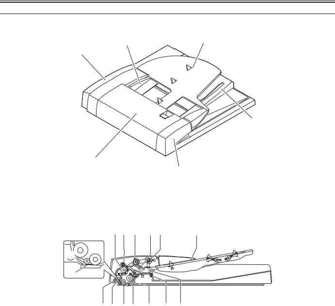
1.2.1 External View
[3] |
[4] |
|
[2]
[6]
[1]
|
|
[5] |
|
F-1-1 |
|
|
T-1-2 |
|
[1] Feeder cover |
|
[4] Document pickup tray |
[2] Rear cover |
|
[5] Front cover |
[3] Slide guide |
|
[6] Document delivery tray |
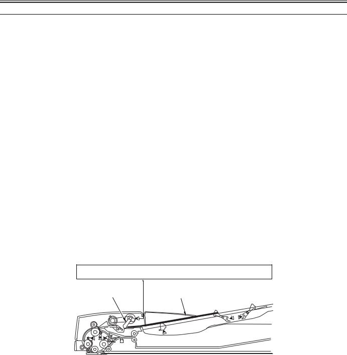
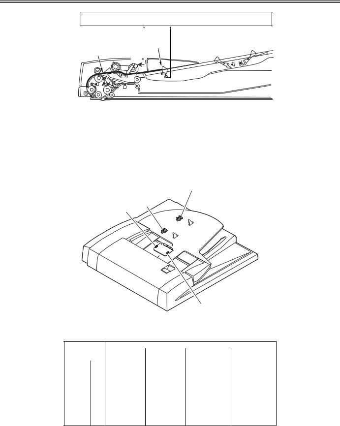
1.2.2 Cross-section |
|
|
[1] [2] [3] |
[4] [5] |
[6] |
[12] |
|
|
[15] |
|
|
[14] [13] [11] [10] |
[9] |
[8] |
[7] |
F-1-2
[1]Lower registration roller
[2]Upper registration roller
[3]Separation roller
[4]Separation pad
[5]Pickup roller
[6]Document supply tray
[7]Upper delivery reversal roller
[8]Lower delivery reversal roller
[9]Read roller 2 (lower)
[10]Read roller 2 (upper)
[11]Platen roller
[12]Read roller
[13]Read roller 1 (upper)
[14]Read roller 1 (lower)
[15]White sheet
1-2

Chapter 2 Functions
Contents
Contents
2.1 Basic Construction ............................................................................................................................................. |
2-1 |
2.1.1 Outline of Electric Circuit ........................................................................................................................... |
2-1 |
2.2 Basic Operation .................................................................................................................................................. |
2-1 |
2.2.1 Drive Mechanism and Signals..................................................................................................................... |
2-1 |
2.2.2 Outline of Operation Mode ......................................................................................................................... |
2-2 |
2.2.3 Forward Pickup/Delivery (Single-sided document > Simplex Printing) Operation ................................... |
2-2 |
2.2.4 Forward Pickup/Reversal Delivery (Double-sided document > Duplex printing) Operation..................... |
2-2 |
2.3 Document Detection........................................................................................................................................... |
2-4 |
2.3.1 Outline ......................................................................................................................................................... |
2-4 |
2.3.2 Document Presence/Absence Detection...................................................................................................... |
2-4 |
2.3.3 Detection of Last Document........................................................................................................................ |
2-4 |
2.3.4 Initial Document Size Detection ................................................................................................................. |
2-5 |
2.4 Document Pickup/Separation ............................................................................................................................. |
2-6 |
2.4.1 Basic Pickup Operation ............................................................................................................................... |
2-6 |
2.4.2 Pickup Unit and Stopper.............................................................................................................................. |
2-7 |
2.4.3 Pickup Timing ............................................................................................................................................. |
2-7 |
2.4.4 Pickup Motor (M2) Control ........................................................................................................................ |
2-7 |
2.5 Document Reversing .......................................................................................................................................... |
2-8 |
2.5.1 Basic Operation ........................................................................................................................................... |
2-8 |
2.5.2 Operation Sequence..................................................................................................................................... |
2-9 |
2.6 Document Feeding/Delivery .............................................................................................................................. |
2-9 |
2.6.1 Basic Operation ........................................................................................................................................... |
2-9 |
2.6.2 Operation Sequence................................................................................................................................... |
2-10 |
2.6.3 Feed Motor (M1) Control.......................................................................................................................... |
2-10 |
2.7 Detecting Jams ................................................................................................................................................. |
2-10 |
2.7.1 Jam............................................................................................................................................................. |
2-10 |
2.8 Power Supply ................................................................................................................................................... |
2-11 |
2.8.1 Power Supply ............................................................................................................................................ |
2-11 |
2.9 Stamp Operation............................................................................................................................................... |
2-11 |
2.9.1 Outline ....................................................................................................................................................... |
2-11 |
Chapter 2
2.1 Basic Construction
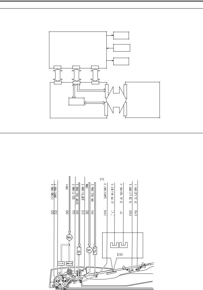
2.1.1 Outline of Electric Circuit
Electric circuits of this machine are controlled by the reader controller PCB and image processor PCB. The ASICs on the reader controller PCB and image processor PCB detect the signals received from the host machine to output the signals that drive DC loads such as motors and solenoids at the predetermined timings. The reader controller PCB and image processor PCB do not have a memory area; data (service mode, etc.) is stored in the image processor PCB.
|
Motor |
ADF driver PCB |
Sensor |
|
|
|
|
Solenoid |
CN10 |
CN1 |
CN2 |
|
|
+24V |
|
|
+3.3V |
|
J410 |
J412 |
J411 |
|
|
|
|
|
J403 |
J308 |
|
ASIC(IC2) |
|
|
|
Reader controller PCB |
J404 |
J309 |
||
|
|
|
F-2-1 |
|
2.2 Basic Operation
Image processor PCB
2.2.1 Drive Mechanism and Signals
This machine is a document feeder exclusively for stream reading. This machine uses two motors to pick up and feed document paper.
|
|
|
|
|
|
|
|
|
|
|
|
T-2-1 |
||||||||||||||
|
|
|
|
Name (symbol) |
|
|
|
|
|
|
|
|
|
Function |
||||||||||||
|
|
|
|
|
|
|
|
|
|
|
|
|
|
|
|
|
|
|
|
|
|
|
|
|
|
|
|
|
|
|
Feed motor (M1) |
|
|
|
|
|
|
|
|
Feeds documents. |
|||||||||||||
|
|
|
|
Pickup motor (M2) |
|
|
|
|
|
Separates and feeds documents. |
||||||||||||||||
The drive mechanism and signals are shown below. |
|
|
|
|
|
|
|
|
|
|
|
|
|
|
|
|
||||||||||
|
|
|
|
|
|
|
|
|
|
|
|
|
|
|
|
|
|
|
|
|
|
|
|
|
|
|
|
|
|
|
|
|
|
|
|
|
|
|
|
|
|
|
|
|
|
|
|
|
|
|
|
|
|
|
|
|
|
|
|
|
|
|
|
|
|
|
|
|
|
|
|
|
|
|
|
|
|
|
|
|
|
|
|
|
|
|
|
|
|
|
|
|
|
|
|
|
|
|
|
|
|
|
|
|
|
|
|
|
|
|
|
|
|
|
|
|
|
|
|
|
|
|
|
|
|
|
|
|
|
|
|
|
|
|
|
|
|
|
|
|
|
|
|
|
|
|
|
|
|
|
|
|
|
|
|
|
|
|
|
|
|
|
|
|
|
|
|
|
|
|
|
|
|
|
|
|
|
|
|
|
|
|
|
|
|
|
|
|
|
|
|
|
|
|
|
|
|
|
|
|
|
|
|
|
|
|
|
|
|
|
|
|
|
|
|
PI7 PI8 |
PI6 |
PI11 |
PI3 |
PI4 |
PI5 |
|
|
|
PI2 |
PI1 |
|
|
|
2 |
|
|
|
F-2-2
2-1
Chapter 2
[1]ADF driver PCB
[2]Document detection signal
[3]Document detection signal
[4]Pickup motor drive signal
[5]Document placement signal
[6]Stamp solenoid drive signal
[7]Document placement signal
[8]Feed motor drive signal
[9]Roller release solenoid drive signal
[10]Last document detection signal
[11]Paper size (width) identification signal 1
[12]Paper size (width) identification signal 2
[13]Paper size (length) identification signal 1
[14]Paper size (length) identification signal 2
[15]Relay PCB
2.2.2 Outline of Operation Mode
This machine has four operation modes. This machine operates in the operation mode specified by the host machine to perform printing. Operation mode names, brief outline of operations, and associated print modes are given in the following table:
|
T-2-2 |
|
Operation mode name |
Outline of operation |
Associated print mode |
|
|
|
[1] Forward pickup/delivery |
Picks up, reads, and then delivers an document. |
Single-sided document > |
|
|
Simplex printing |
|
|
Single-sided document > |
|
|
Duplex printing (This operation |
|
|
is performed for documents |
|
|
with the same width/different |
|
|
width.) |
[2] Forward feed/reversal |
Picks up, reads, reverses, and delivers an |
delivery |
document. |
Double-sided document > Duplex printing Double-sided document > Simplex printing (This operation is performed for documents with the same width/different width.)
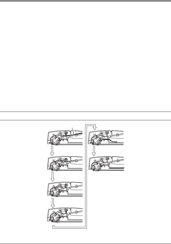
2.2.3 Forward Pickup/Delivery (Single-sided document > Simplex Printing) Operation
The document flows as shown below.
MEMO:
This operation is performed for all single-sided documents irrespective of whether document widths are the same or different.
Document
Pickup |
Delivery |
Formation of loop |
End of job |
Waiting for reading
Reading
F-2-3
2.2.4 Forward Pickup/Reversal Delivery (Double-sided document > Duplex printing) Operation
The document flow is shown below.
MEMO:
2-2

Chapter 2
This operation is performed for all double-sided documents irrespective of whether document widths are the same or different.
Document
Pickup |
Feed |
Formation of loop |
Reversal |
Waiting for reading |
Formation of loop |
Reading |
Waiting for reading |
to next page
F-2-4
Reverse side reading |
Feed |
Feed |
Idle feed |
Reversal |
Delivery |
Feed |
End of job |
F-2-5
2-3
Chapter 2
2.3 Document Detection
2.3.1 Outline
This machine detects an document using either one of the two methods depending on the print mode.
-Normal print mode (other than mixed size print mode and banner paper mode)
-Mixed size print mode and banner paper mode
a. Normal print mode (other than mixed size print mode and banner paper mode)
In the normal print mode, the following four document detection functions are used:
|
T-2-3 |
|
Function |
Description |
Sensor used (symbol) |
|
|
|
Document presence/ |
Detects whether there is an document on the |
Document set sensor (PI11) |
absence detection |
document pickup tray. |
|
Last document detection |
Detects whether the document being picked up is |
Last document detection sensor |
|
the last one. |
(PI3) |
Initial document size |
|
|
detection |
|
|
- Longitudinal direction |
Detects the length of the document placed on the |
|
document pickup tray. |
- Lateral direction |
Detects the width of the document placed on the |
|
document pickup tray. |
Document length sensor 1/2 (PI4/ PI5)
Document width sensor 1/2 (PI2/ PI1)
b. Mixed size print mode and banner paper mode
In the mixed size print mode and banner paper mode, the following three document detection functions are used:
|
T-2-4 |
|
Function |
Description |
Sensor used (symbol) |
|
|
|
Document presence/ |
Detects whether there is a document |
Document set sensor (PI11) |
absence detection |
on the document pickup tray. |
|
Last document detection |
Detects whether the document being |
Last document detection sensor (PI3) |
|
picked up is the last one. |
|
Document length detection |
Detects the document length |
Read sensor (PI7) |
|
according to the distance from the |
|
|
position where the read sensor (PI7) |
|
|
turns on to the position where the read |
|
|
sensor (I7) turns off. |
|
2.3.2 Document Presence/Absence Detection
The Document set sensor (PI11) detects presence/absence of a document on the document tray.
When a document is placed on the document tray, the detection lever moves the light shielding plate to allow light to pass thorough the photo interrupter. Thus, the Document set sensor (PI11) generates an document detection signal (EMPTY) to notify the host machine that an document is placed on the document tray via the ADF drive PCB.
ADF driver PCB
Detection lever
PI11
EMPTY
Document
F-2-6
2.3.3 Detection of Last Document
The last document detection sensor (PI3) and Document set sensor (PI11) detect whether the document being picked up is the last one.
When the trailing edge of the last document has moved past the last document detection lever, the detection lever moves the light shielding plate to allow light pass through the photo interrupter. Thus, the last document detection sensor (PI3) generates a last document detection signal (LAST). When the last document has moved past the document sensor (PI11), an document absence signal (EMPTY) is generated to notify the host machine that an document being picked up is the last one via the ADF drive PCB.
2-4
Chapter 2
Document
ADF driver PCB
EMPTY |
Detection |
LAST |
|
|
|
|
lever |
|
PI11 |
|
|
|
PI3 |
|
F-2-7
2.3.4 Initial Document Size Detection
The document length sensor 1 (PI4) and document length detection sensor 2 (PI5) detect the longitudinal size of the document placed on the document tray, and the document width sensor 1 (PI2) and document width sensor 2 (PI1) detect the lateral size of the document.
When an document is placed on the document tray, detection levers of the two document length sensors move the light shielding plate to allow light pass through the photo interrupter.
If the slide guide is adjusted to the document size, the two document width sensors mounted inside the document tray are shielded by the light shielding plate mounted at the bottom of the slide guide.
Document sizes are determined by the combination of the ON/OFF states of document length sensors and the combination of ON/OFF states of document width sensors.
PI5
PI4
PI2
PI1
F-2-8
The following tables show the relationships among document width sensors, document length sensors, and document sizes.
1. AB type
T-2-5
|
|
|
Sensor name |
|
|
|
|
|
|
|
|
|
|
Document width |
Document width |
Document length |
Document length |
|
|
sensor 1 |
sensor 2 |
sensor 1 |
sensor 2 |
|
|
|
|
|
|
|
A3 |
ON |
ON |
ON |
ON |
|
|
|
|
|
|
|
B4 |
OFF |
ON |
ON |
ON |
|
|
|
|
|
|
|
A4R |
OFF |
OFF |
ON |
OFF |
|
|
|
|
|
|
|
B5R |
ON |
OFF |
ON |
OFF |
Size |
|
|
|
|
|
A4 |
ON |
ON |
OFF |
OFF |
|
|
|
|
|
|
|
|
A5R |
ON |
OFF |
OFF |
OFF |
|
|
|
|
|
|
|
B5 |
OFF |
ON |
OFF |
OFF |
|
|
|
|
|
|
|
A5 |
OFF |
OFF |
OFF |
OFF |
|
|
|
|
|
|
|
B6 |
ON |
OFF |
OFF |
OFF |
2. Inch type
2-5
Loading...