


 Loading...
i9900
SERVICE
MANUAL
Canon
Copyright 2004, Canon U.S.A. This technical publication is the proprietary and confidential information of Canon U.S.A. which shall be retained for reference purposes by Authorized Service Facilities of Canon U.S.A. Its unauthorized use is prohibited.
i9900/i9950 REFERENCE MANUAL
Revision 0
QY8-1397-000
Scope
This manual has been issued by Canon Inc., to provide the service technicians of this product with the information necessary for qualified persons to learn technical theory, installation, maintenance, and repair of products. The manual covers information applicable in all regions where the product is sold. For this reason, it may contain information that is not applicable to your region.
Revision
This manual could include technical inaccuracies or typographical errors due to improvements or changes made to the product. When changes are made to the contents of the manual, Canon will release technical information when necessary. When substantial changes are made to the contents of the manual, Canon will issue a revised edition.
The following do not apply if they do not conform to the laws and regulations of the region where the manual or product is used:
Trademarks
Product and brand names appearing in this manual are registered trademarks or trademarks of the respective holders.
Copyright
All rights reserved. No parts of this manual may be reproduced in any form or by any means or translated into another language without the written permission of Canon Inc., except in the case of internal business use.
Copyright 2004 by Canon Inc. CANON INC.
Inkjet Products Quality Assurance Div.
16-1, Shimonoge 3-chome, Takatsu-ku, Kawasaki, Kanagawa 213-8512, Japan
I.MANUAL OUTLINE
This manual outlines the main service information for the i9900 / i9950 models.
Product names, availability of CD-R printing, and destination are as follows.
Product name |
Availability of CD-R printing |
Destination |
i9950 |
Yes |
EUR/ASA HVT/AU/GB/TW/HK/CN/EUM |
i9900 |
No |
US/CA/LAM LVT/LAM HVT/KR |
PIXUS 9900i |
Yes |
JPN |
II.TABLE OF CONTENTS
Page |
Part 1: |
MAINTENANCE |
|
1-1 |
1. |
MAINTENANCE |
|
1-1 |
|
1.1 |
Adjustment, Periodic Maintenance, Periodic Replacement Parts, and Replacement |
|
|
|
Consumables by Service Engineer |
1-2 |
|
1.2 |
Customer Maintenance |
1-3 |
|
1.3 |
Product Life |
1-3 |
|
1.4 |
Special Tools |
1-3 |
|
1.5 |
Serial Number Location |
1-4 |
2. LIST OF ERROR DISPLAY / INDICATION |
||
1-4 |
|
2.1 |
Operator Call Errors (LED Blinks in Orange) |
1-6 |
|
2.2 |
Service Call Errors (LED Blinks in Orange and Green Alternately, or Lights in |
|
|
|
Orange) |
1-6 |
|
2.3 |
Warnings |
1-7 |
|
2.4 |
Troubleshooting by Symptom |
1-9 |
3. |
REPAIR |
|
1-9 |
|
3.1 |
Disassembling / Reassembling flow for main units |
1-10 |
|
3.2 |
Notes on Service Part Replacement (and Disassembling / Reassembling) |
1-11 |
|
3.3 |
Special Notes on Repair Servicing |
(1)Flexible cable and harness wiring, connection
(2)Notes on after repair for trouble concerning printing or re-installation of the
|
|
|
print head |
1-12 |
3.4 |
(1) |
Paper feed motor adjustment |
|
|
(2) |
Gear phase adjustment |
1-13 |
|
(3) |
Grease application |
1-14 |
|
(4) |
Waste ink counter setting |
1-15 |
|
(5) |
User mode |
1-15 |
|
(6) |
Service mode |
1-17 |
|
(7) |
Flash ROM upgrade |
1-17 |
3.5 |
Verification Item |
|
|
|
(1) |
Service test print |
1-20 |
|
(2) |
EEPROM information print |
1-22 |
4. PRINTER TRANSPORTATION METHOD |
||
Part 2: TECHNICAL REFERENCE
2-1 1. NEW TECHNOLOGIES
2-4 2. CLEANING MODE AND AMOUNT OF INK PURGED 2-5 3. PRINT MODE
|
3.1 |
Resolution |
|
|
|
(1) |
Standard color printing |
2-6 |
|
(2) Standard gray scale printing (Paper types different than those for color printing |
|
|
|
|
only are listed.) |
2-7 |
|
(3) |
Borderless printing |
|
|
(4) |
Duplex printing |
2-8 |
|
(5) |
Camera Direct Printing |
2-9 |
4. FAQ (Specific Problems and Solutions) |
||
2-10 |
5. SPECIFICATIONS |
||
2-10 |
5.1 |
Printer Specifications |
|
2-11 |
5.2 |
Printer Head Specifications |
|
|
5.3 Comparison with PIXUS 9100i / i9100 |
||
|
Part 3: |
APPENDIX |
|
3-1 |
1. |
BLOCK DIAGRAM |
|
3-2 |
2. |
CONNECTOR LOCATION AND PIN LAYOUT |
|
3-2 |
|
2.1 |
Logic Board Ass’y |
3-6 |
|
2.2 |
Carriage Board (print head connection terminals) |
Part 1
MAINTENANCE
1.MAINTENANCE
1.1Adjustment, Periodic Maintenance, Periodic Replacement Parts, and Replacement Consumables by Service Engineer
(1)Adjustment
Adjustment |
Timing |
Purpose |
Tool |
Approx. |
|
time |
|||||
|
|
|
|
||
EEPROM |
At logic board ass’y |
To initialize settings other |
None. |
1 min. |
|
initialization |
replacement |
than the following: |
|
|
|
(EEPROM settings) |
|
- USB serial number |
|
|
|
|
|
- Destination setting |
|
|
|
|
|
- Waste ink counter |
|
|
|
|
|
- Media sensor correction |
|
|
|
|
|
value |
|
|
|
|
|
- CD-R correction value |
|
|
|
|
|
- Correction value for the |
|
|
|
|
|
CDR sensor and |
|
|
|
|
|
automatic print head |
|
|
|
|
|
alignment sensor |
|
|
|
Destination settings |
At logic board ass’y |
To set the destination. |
None. |
1 min. |
|
(EEPROM settings) |
replacement |
|
|
|
|
Waste ink counter |
- At bottom case/output |
To reset the waste ink |
None. |
1 min. |
|
resetting |
tray unit (bottom case |
counter. |
|
|
|
(EEPROM settings) |
unit) replacement |
|
|
|
|
|
- At ink absorber |
|
|
|
|
|
replacement |
|
|
|
|
Media sensor |
- At logic board ass’y |
To correct the media |
Calibration media |
2 min. |
|
correction*1 |
replacement |
sensor. |
kit (QY9-0064)*2 |
|
|
(EEPROM settings) |
- At sheet feeder unit |
|
|
|
|
|
replacement |
|
|
|
|
Correction for the |
- At logic board ass’y |
To correct the CD-R sensor |
None. |
1 min. |
|
CD-R sensor and |
replacement |
and automatic print head |
(Correction |
|
|
automatic print head |
- At carriage unit |
alignment sensor. |
performed |
|
|
alignment sensor |
replacement |
|
through service |
|
|
(EEPROM settings) |
|
|
test print) |
|
|
Print head alignment |
- At print head |
To ensure accurate dot |
Computer |
3 min. |
|
|
replacement |
placement. |
(settings via the |
|
|
|
- At logic board ass’y |
|
printer driver) |
|
|
|
replacement |
|
|
|
|
Paper feed motor |
At paper feed motor unit |
To adjust the belt tension. |
None. |
2 min. |
|
position adjustment*3 |
replacement |
(Position the paper feed |
|
|
|
|
|
motor so that the belt is |
|
|
|
|
|
stretched tight.) |
|
|
|
Grease/oil |
- At carriage |
- To maintain sliding |
- FLOIL |
2 min. |
|
application*4 |
shaft/grease pad |
properties of the carriage |
KG-107A |
|
|
|
replacement |
and paper guide flapper. |
(QY9-0057) |
|
|
|
- At paper guide flapper |
- To protect the lift base |
- MOLYKOTE |
|
|
|
ass’y/carriage slide |
gear. |
PG641 |
|
|
|
sheet/shaft clip |
- To maintain sliding |
(CK-0562) |
|
|
|
replacement |
properties of the |
- EU-1 |
|
|
|
- At lift base gear part |
operation lever |
(QY9-0037) |
|
|
|
replacement |
|
|
|
|
|
- At gear box |
|
|
|
|
|
replacement |
|
|
|
1 - 1
|
Cautions after print |
- After repair for trouble |
- To prevent non-ejection |
None. |
6 min. |
||
|
head installation*5 |
concerning printing |
of ink at initial printing |
|
|
||
|
|
|
|
- After re-installation of |
(Empty ink from print |
|
|
|
|
|
|
the print head |
head once.) |
|
|
|
|
|
|
(Before returning to |
|
|
|
|
|
|
|
users) |
|
|
|
|
|
|
|
|
|
|
|
Note: |
DO NOT loosen the red screws on both sides of the main chassis securing the carriage shaft position. |
||||||
*1: |
Media sensor correction |
|
|
|
|||
|
|
This operation adjusts the correction value of the media sensor, installed in the sheet feeder unit, to the |
|||||
|
|
EEPROM of the logic board ass’y. The adjustment is required when the sheet feeder unit or the logic board |
|||||
|
|
ass’y is replaced, and values are automatically determined via use of calibration media kit (QY9-0064). |
|||||
*2: |
Calibration media kit |
|
|
|
|
||
|
|
The service tool for media sensor correction, consisting of 10 sheets of the reference plain paper, and 1 |
|||||
|
|
sheet of the reference white PET paper. |
|
|
|
||
*3: Red screws of paper feed motor
The red screws securing the paper feed motor may be loosened only at replacement of the paper feed motor unit.
*4: For details, see Section 3.4 Adjustment / Settings.
*5: Cautions after repair for trouble concerning printing or the print head re-installation
After repair for trouble concerning printing or the print head re-installation, after emptying the ink in the print head, (if users sent the printer with ink tanks, re-set it with ink tanks) and return the printer to users. (See Section 3.3 Special Notes on Repair Servicing (2) Notes on after repair for trouble concerning printing or re-installation of the print head.)
(2)Periodic maintenance
No periodic maintenance is necessary.
(3)Periodic replacement parts
There are no parts in this printer that require periodic replacement by a service engineer.
(4)Replacement consumables
There are no consumables that require replacement by a service engineer.
1.2Customer Maintenance
Adjustment |
Timing |
Purpose |
Tool |
Approx. |
|
time |
|||||
|
|
|
|
||
Print head alignment |
At print head |
To ensure accurate |
Computer (Automatic |
5 min. |
|
|
replacement. |
dot placement. |
settings via the printer |
|
|
|
|
|
driver) |
|
|
Print head cleaning |
When print quality is |
To improve nozzle |
- Printer buttons |
30 sec. to |
|
|
not satisfying. |
conditions. |
- Computer (settings |
1 min. |
|
|
|
|
via the printer |
|
|
|
|
|
driver) |
|
|
Print head deep cleaning |
When print quality is |
To improve nozzle |
Computer (settings |
1 to 1.5 |
|
|
not satisfying, and |
conditions. |
via the printer driver) |
min. |
|
|
not improved by |
|
|
|
|
|
print head cleaning. |
|
|
|
|
Ink tank replacement |
When an ink tank |
----- |
----- |
2 min. |
|
|
becomes empty. |
|
|||
|
(No ink error) |
|
|
|
|
Paper feed roller |
When paper does not |
To clean the paper |
Printer buttons |
2 min. |
|
cleaning |
feed properly |
feed rollers. |
|
|
|
CD-R print position |
When printing to |
To ensure accurate |
Computer (Settings |
5 min. |
|
alignment |
CD-R |
CD-R print position |
via the application) |
|
|
Cleaning inside the |
When the backside |
To remove ink mist |
|
1 min |
|
printer |
of paper is dirty. |
adhered to the |
----- |
|
|
|
|
platen rib, using a |
|
||
|
|
|
|
||
|
|
cloth. |
|
|
1 - 2
1.3Product Life
(1)Printer
The value from (i) to (iii), whichever comes first.
(i)10,000 pages of color printing
-Color: 7.5% duty per color pattern printing, A4
(ii)1,200 discs of CD-R/DVD-R printing
-On a basis of monthly print volume of approx. 20 discs
(iii)5 years of use
(2)Print head
10,000 pages of color printing
-Color: 7.5% duty per color pattern printing, A4
(3)Ink tank
BCI-6BK: |
740 pages (1,500 character pattern in black printing, plain paper, standard mode) |
|
1,100 pages (ISO JIS-SCID No. 5 pattern, plain paper, standard mode) |
BCI-6C: |
1,100 pages (ISO JIS-SCID No. 5 pattern, plain paper, standard mode) |
BCI-6M: |
790 pages (ISO JIS-SCID No. 5 pattern, plain paper, standard mode) |
BCI-6Y: |
540 pages (ISO JIS-SCID No. 5 pattern, plain paper, standard mode) |
BCI-6PC: |
380 pages (ISO JIS-SCID No. 5 pattern, plain paper, standard mode) |
BCI-6PM: |
280 pages (ISO JIS-SCID No. 5 pattern, plain paper, standard mode) |
BCI-6R: |
2,300 pages (ISO JIS-SCID No. 5 pattern, plain paper, standard mode) |
BCI-6G: |
2,300 pages (ISO JIS-SCID No. 5 pattern, plain paper, standard mode) |
1.4Special Tools
Name |
Tool No. |
Purpose |
Remarks |
MOLYKOTE PG641 |
CK-0562-000 |
To be applied to the lift base |
In common with |
|
|
bushing, the lift gear, the gear |
conventional models |
|
|
box, and the CD-R tray lever |
|
FLOIL KG-107A |
QY9-0057-000 |
To be applied to the sliding |
In common with |
|
|
portions of the carriage slider |
conventional models |
|
|
sheet, carriage shaft clip, the |
|
|
|
paper guide flapper, and the idle |
|
|
|
pulley |
|
EU-1 |
QY9-0037-000 |
To be applied to the sliding |
In common with |
|
|
portion of the carriage, and the |
conventional models |
|
|
oil pad on the carriage |
|
Calibration media kit |
QY9-0064-000 |
To correct the media sensor |
In common with |
|
|
|
conventional models |
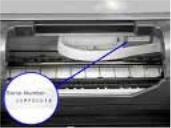
1.5Serial Number Location
On the label on the chassis (visible to the right of the flexible cable when the access cover is open).
The image to the right is an example for the PIXUS 9900i model: FBYX10885
1 - 3

2.LIST OF ERROR DISPLAY / INDICATION
Errors are indicated by the LED, and warnings are displayed on the monitor of the computer connected to the printer.
2.1Operator Call Errors (LED Blinks in Orange)
LED |
Error |
Solution |
Remarks |
Blinks in |
|||
orange |
|
|
|
2 times |
No paper. / Pick up failure. (Sheet |
Set paper (set properly again.) |
|
|
feeder unit) [1000] |
in the Sheet feeder unit, and |
|
|
|
press the Resume/Cancel |
|
|
|
button. |
|
|
No CD-R tray [1001]*1 |
Set the CD-R tray*2, and press |
Adjust the mark on the |
|
|
the Resume/Cancel button. |
CD-R tray to the mark |
|
|
|
on the paper output |
|
Paper jam. [1300] |
Remove the jammed paper, and |
tray. *3 |
3 times |
|
||
|
|
press the Resume/Cancel |
|
|
No ink. |
button. |
|
4 times |
Replace the empty ink tank(s), |
Pressing the |
|
|
[1601/1611/1612/1613/1614/1634/ |
or press the Resume/Cancel |
Resume/Cancel button |
|
1635] |
button. |
will exit the error |
|
|
|
without ink tank |
|
|
|
replacement, however, |
|
|
|
ink may run out during |
|
|
|
printing. |
5 times |
The print head is not installed [1401], |
Install the print head properly, |
|
|
or it is not properly installed |
and close the access cover. |
|
|
(EEPROM data of the print head is |
Or, with the print head |
|
|
faulty) [1403/1405]. |
installed, turn the printer off |
|
|
|
and on. |
|
6 times *1 |
The paper output tray is in the CD-R |
Remove the CD-R tray*2, set |
|
|
printing position. (On paper printing) |
the paper output tray in the |
|
|
[1850/1855] |
paper printing position, and |
|
|
|
press the Resume/Cancel |
|
|
|
button. |
|
|
The paper output tray is in the paper |
Set the paper output tray in the |
|
|
printing position. (On CD-R printing) |
CD-R printing position, set the |
|
|
[1851/1856] |
CD-R tray*2, and press the |
|
|
|
Resume/Cancel button. |
|
|
|
|
|
7 times *1 |
NO CD-R/DVD-R [1002] *1 |
Set the CD-R/DVD-R on the |
|
|
|
CD-R tray*2, set the CD-R |
|
|
|
tray*2, and press the |
|
|
|
Resume/Cancel button. |
|
8 times |
Warning: The waste ink absorber is |
Pressing the Resume/Cancel |
The waste ink full |
|
almost full (approx. 95% of the |
button will exit the error, and |
error (service call |
|
maximum capacity). [1700] |
enable printing. |
error) may occur. |
|
|
In repair servicing, replace the |
|
|
|
bottom case/output tray unit |
|
|
|
(bottom case unit), or the ink |
|
|
|
absorbers. |
|
9 times |
The connected digital camera or |
After removing the cable |
When a camera |
|
digital video camera does not support |
connecting the camera and the |
supporting direct |
|
Camera Direct Printing. [2001] |
printer, press the |
printing is connected, |
|
|
Resume/Cancel button, and |
the LED blinks in |
|
|
re-connect the cable. |
green two times. |
1 - 4
(Operator Call Errors - cont’d -)
LED |
Error |
|
Solution |
Remarks |
blinking |
|
|||
in orange |
|
|
|
|
11 times |
Automatic print head alignment |
Press the Resume/Cancel |
|
|
|
failure [2500] |
button, and after confirming the |
|
|
|
|
following, perform print head |
|
|
|
|
alignment again: |
|
|
|
|
- |
Set an appropriate type and |
|
|
|
|
size of paper (plain paper, A4 |
|
|
|
|
or letter). |
|
|
|
- |
Check that the print head |
|
|
|
|
alignment pattern is properly |
|
|
|
|
printed (all ink ejected, no |
|
|
|
|
faint printing). |
|
|
|
- |
Check that the paper ejection |
|
|
|
|
slot is not exposed to light. |
|
|
|
- When there are no problems |
|
|
|
|
|
in the three items above, |
|
|
|
|
perform manual print head |
|
|
|
|
alignment. |
|
*1: Only the i9950 model supports CD-R printing.
*2: Use the CD-R tray with a “A” mark in the lower left. (Using a CD-R tray with no mark is not possible.)
Use the CD-R tray with an “A” mark.
When not performing CD-R printing, store the CD-R tray by hanging it on the projections on the back side of the printer.
*3: When setting the CD-R, align the marks on the CD-R tray to the marks on the paper output tray.
1 - 5
2.2 Service Call Errors (LED Blinks in Orange and Green Alternately, or Lights in Orange)
LED blinks |
|
Solution |
|
alternately in |
Error |
||
(Replacement of listed parts, which are likely to be faulty) |
|||
orange and green |
|
||
|
|
||
2 times |
Carriage error [5100] |
- Carriage unit (QM2-1306) |
|
|
|
- Timing slit strip film (QC1-4520) |
|
|
|
- Logic board ass’y (QM2-1272/QM2-1273)*1 |
|
|
|
- Carriage motor (QK1-0175) |
|
3 times |
Paper feed error [6000] |
- Timing sensor unit (QM2-1322) |
|
|
|
- Timing slit disk film (QC1-2484) |
|
|
|
- Feed roller ass’y (QL2-0626) |
|
|
|
- Platen unit (QM2-1304/1327) |
|
|
|
- Logic board ass’y (QM2-1272/QM2-1273)*1 |
|
|
|
- Paper feed motor unit (QK1-0637) |
|
4 times |
Purge unit error [5C00] |
- Purge unit (QM2-1307) |
|
|
|
- Logic board ass’y (QM2-1272/QM2-1273)*1 |
|
6 times |
Internal temperature error [5400] |
- Logic board ass’y (QM2-1272/QM2-1273)*1 |
|
7 times |
Waste ink absorber full [5B00] |
- Ink absorber (QC1-4613/4614/4615/4641) |
|
|
|
- Bottom case unit (QM2-1325)*3 |
|
|
|
- Bottom case/Output tray unit (QM2-1328)*3 |
|
8 times |
Print head temperature rise error |
- Print head (QY6-0055) |
|
|
[5200] |
- Logic board ass’y (QM2-1272/QM2-1273)*1 |
|
9 times |
EEPROM error [6800] |
- Logic board ass’y (QM2-1272/QM2-1273)*1 |
|
10 times*2 |
Carriage lift mechanism error |
- Lift input gear shaft (QC1-2657) |
|
|
[5110] |
- Photo interrupter (WG8-5571) |
|
|
|
- Lift cam harness ass’y (QM2-1281) |
|
|
|
- Sheet feeder unit (QM2-1329) |
|
|
|
- Logic board ass’y (QM2-1272/QM2-1273)*1 |
|
12 times |
Media sensor error [8000] |
- Sheet feeder unit (QM2-1329) |
|
|
|
|
|
13 times |
USB Host VBUS overcurrent |
- Logic board ass’y (QM2-1272/QM2-1273)*1 |
|
|
[9000] |
|
|
15 times |
Other hardware error [6500] |
- Logic board ass’y (QM2-1272/QM2-1273) *1 |
|
|
|
|
|
Continuous |
Flash ROM error |
- Logic board ass’y (QM2-1272/QM2-1273)*1 |
|
alternate blinking |
|
|
|
Lights in orange |
RAM error |
- Logic board ass’y (QM2-1272/QM2-1273)*1 |
|
|
|
|
*1: Before replacement of the logic board ass’y, check the waste ink amount (by service test print or EEPROM information print). If the waste ink amount is 7% or more, also replace the bottom case/output tray unit (bottom case unit) or the complete set of the ink absorbers when replacing the logic board ass’y. See Section 3.4. Adjustment / Settings, (6) Service mode, for details.
*2: Only for the 9950i model supporting CD-R printing.
*3: Reset the waste ink counter when replacing the bottom case/output tray unit (bottom case unit). See Section
3.4.Adjustment / Settings, (6) Service mode, for details.
2.3Warnings
(1)Printer (no LED indications)
Displayed warning |
Remarks |
|
|
Low ink of 6BK, 6C, 6M, 6Y, 6PC, 6PM, 6R, and 6G (at |
The status is displayed on the monitor of the |
detection of no remaining raw ink) |
computer connected to the printer. |
Print head temperature rise warning |
If the print head temperature is high when the |
|
access cover is opened, the warning is |
|
displayed*1. When the print head temperature |
|
falls, the warning is released. |
Print head temperature excess rise protection |
If the print head temperature exceeds the |
|
specified limit, a Wait is inserted during |
1 - 6

printing.
The paper output tray is in the CD-R printing position when the access cover is opened. When the paper output tray is set in the paper printing position and the access cover is closed, the warning is released.
The paper output tray is in the paper printing position when the access cover is opened. When the paper output tray is set in the CD-R printing position and access cover is closed, the warning is released.
*1: If the warning is displayed, the carriage does not move to the ink tank replacement position when the access cover is opened.
*2: Only for the i9950 model supporting CD-R printing.
2.4Troubleshooting by Symptom
|
Symptom |
Solution |
Remarks |
Faulty |
The power does not turn on. |
Replace the |
|
The power turns off immediately |
- AC adapter, or |
|
|
|
*1 |
|
|
after power-on. |
- logic board ass’y . |
|
|
operation |
|
||
The print head is not recognized. |
Remove and re-install the print head, or replace the |
|
|
The print head does not move to |
- print head, or |
|
|
the home position. |
- logic board ass’y*1, or |
|
|
|
- carriage unit. |
|
|
|
|
|
|
|
A strange noise occurs. |
Remove foreign material, or attach a removed part if any. |
|
|
Printing stops mid-way. |
Replace the logic board ass’y*1, or the |
|
|
|
- print head. |
|
feed Paper problems |
Multiple sheets feed. |
Replace the |
|
|
- sheet feeder unit. |
|
|
Paper does not feed. |
Remove foreign material, or replace the |
|
|
|
|
- sheet feeder unit. |
|
|
Paper feeds at an angle. |
Remove foreign material, adjust paper and the paper |
|
|
|
guide, or replace the |
|
|
|
- sheet feeder unit. |
|
1 - 7

(Troubleshooting by Symptom - cont’d -)
|
Symptom |
Solution |
Remarks |
Unsatisfactory |
No printing, or no ink ejected. *3 |
Replace the |
Perform the |
|
- ink tank, |
cleaning |
|
|
|
- print head*2, |
operation |
|
|
- logic board ass’y*1, or |
(for all |
|
|
- purge unit. |
colors) |
Printing is faint, or white lines |
Remove and re-install the print head, or replace the |
|
|
appear on printouts even after |
- ink tank, |
|
|
quality |
print head cleaning. *3 |
- print head*2, |
|
data appears on printouts. |
- logic board ass’y*1. |
|
|
|
Line(s) not included in the print |
- purge unit, or |
|
|
Paper gets smeared. |
Feed several sheets of paper, or clean the paper path and |
|
|
|
||
|
A part of a line is missing on |
ribs on the platen with cotton swab or cloth. |
|
|
Replace the |
|
|
|
printouts. *3 |
- ink tank, or |
|
|
|
- print head*2. |
|
|
Color hues are incorrect. |
Replace the |
Perform the |
|
|
- ink tank, or |
cleaning |
|
|
- print head*2, or |
operation |
|
|
correct the media sensor, or |
(for all |
|
|
check the ink tank setting position. |
colors) |
|
Printing is incorrect. |
Replace the logic board ass’y*1. |
|
|
No ejection of ink.*3 |
Replace the |
Perform the |
|
|||
|
|
- ink tank, or |
cleaning |
|
|
- print head*2. |
operation |
|
|
|
(for all |
|
Graphic or text is enlarged on |
When enlarged in the carriage movement direction, clean |
colors) |
|
|
||
|
printouts. |
grease or oil off the timing slit strip film, or replace the |
|
|
|
- timing slit strip film, |
|
|
|
- carriage unit, or |
|
|
|
- logic board ass’y*1. |
|
|
|
When enlarged in the paper feed direction, clean grease |
|
|
|
or oil off the timing slit strip film, or replace the |
|
|
|
- timing slit disk film, |
|
|
|
- timing sensor unit, or |
|
|
|
- logic board ass’y*1. |
|
*1: Before replacement of the logic board ass’y, check the waste ink amount (by service test print or EEPROM information print). If the waste ink amount is 7% or more, also replace the bottom case/out put tray unit (bottom case unit) or the complete set of ink absorber when replacing the logic board ass’y. See Section 3.4 Adjustment / Settings, (6) Service mode, for details.
*2: Replace the print head only after the print head deep cleaning is performed 2 times, and when the problem persists.
*3: Before returning the printer to users, empty ink in the print head once.
(See Section 3.3 Special Notes on Repair Servicing (2) Notes on after repair for trouble concerning printing or re-installation of the print head.)
1 - 8

3. REPAIR
3.1 Disassembling/Reassembling flow for main units
The flow chart below shows decomposition in descending order, and assemble in ascending order. (Refer to the PIXUS 9900i/i9900/i9950 Parts Catalogue for details.)
External (Access cover unit, Upper cover unit, Paper support unit, and Side covers, etc.)
|
|
|
|
|
|
|
|
AC adapter |
|
Logic board |
|
Sheet feeder unit |
|
Carriage unit |
|
|
|
|
|
Printer unit
Bottom case/output tray unit (bottom case unit) and Ink absorbers
Platen unit
Purge unit
Reference: Example for the i9100 model (Refer to the PIXUS 9100/i9100 Parts Catalogue for details)
External (Paper support unit, Upper cover unit, and I/F cover, etc.)
AC adapter |
Printer unit |
|
|
|
|
|
|
|
|
|
|
Bottom case unit or Ink |
|
Sheet feeder unit |
|
Carriage |
|
Purge unit |
||
|
|
unit |
|
|||||
absorber |
|
|
|
|
|
|
||
|
|
|
|
|
|
|
||
|
|
|
|
|
|
|
|
|
|
|
|
Logic board |
|
|
|
|
|
1 - 9
Loading...