

Page 1
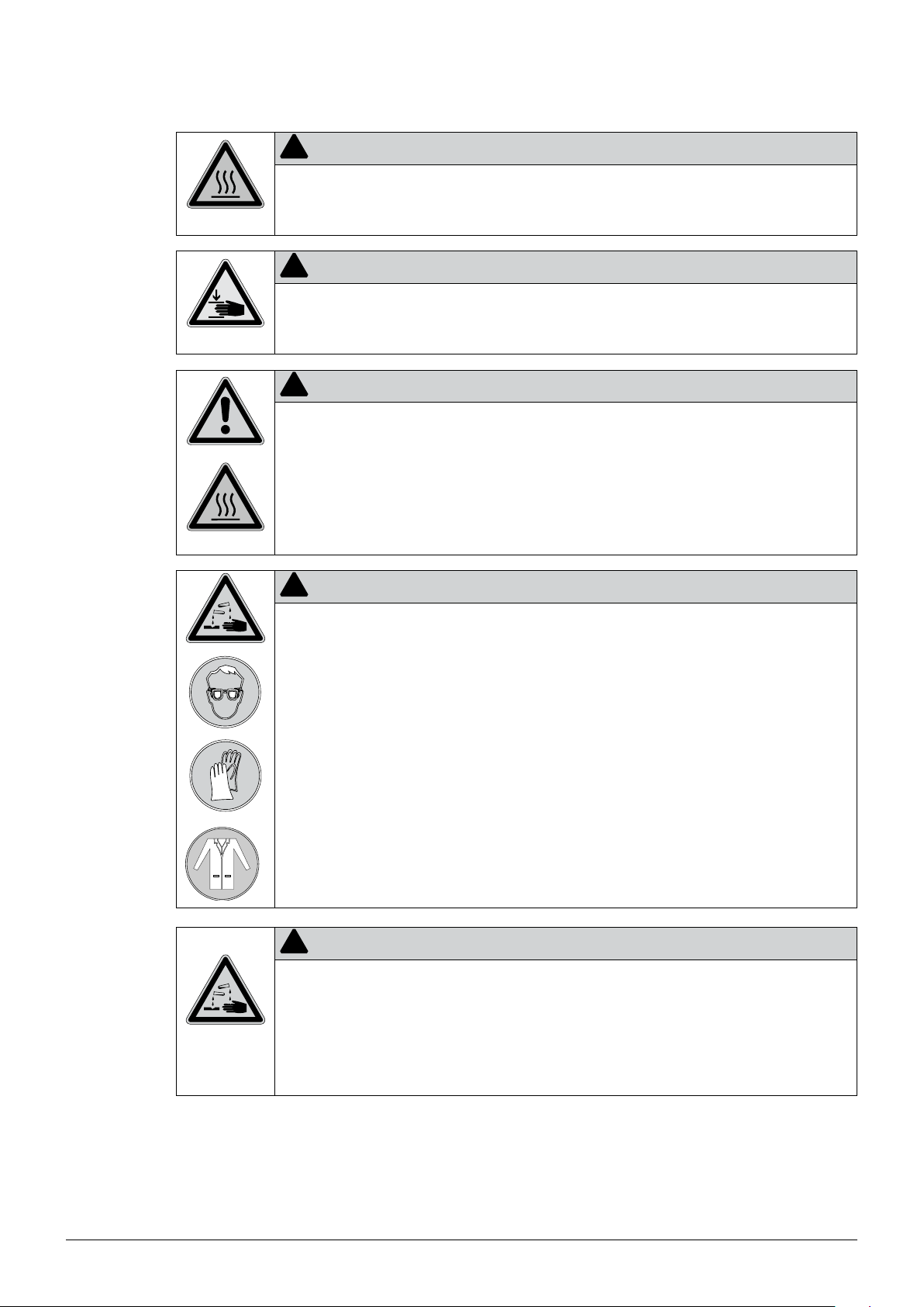
KjelMaster K-375 with KjelSampler K-376/K-377
Operation Manual
11593514 en
Page 2

Page 3

Document History
Index Date Author Changes
A 25/MAY/2012 NAGG Initial version
B 16/JUL/2013 NAGG First revised version
Page 4

Page 5

Table of contents
Table of contents
1 About this manual . . . . . . . . . . . . . . . . . . . . . . . . . . . . . . . . . . . . . . .9
1.1 Trademarks . . . . . . . . . . . . . . . . . . . . . . . . . . . . . . . . . . . . . . . 9
1.2 Abbreviations . . . . . . . . . . . . . . . . . . . . . . . . . . . . . . . . . . . . . . 9
2 Safety. . . . . . . . . . . . . . . . . . . . . . . . . . . . . . . . . . . . . . . . . . . . . 11
2.1 User qualification . . . . . . . . . . . . . . . . . . . . . . . . . . . . . . . . . . . 11
2.2 Proper use . . . . . . . . . . . . . . . . . . . . . . . . . . . . . . . . . . . . . . 11
2.3 Improper use . . . . . . . . . . . . . . . . . . . . . . . . . . . . . . . . . . . . . 11
2.4 Safety warnings and safety signs used in this manual . . . . . . . . . . . . . . . . . 12
2.5 Product safety. . . . . . . . . . . . . . . . . . . . . . . . . . . . . . . . . . . . . 14
2.5.1 General hazards . . . . . . . . . . . . . . . . . . . . . . . . . . . . . . . . . . . . 14
2.5.2 Instrument-related hazards . . . . . . . . . . . . . . . . . . . . . . . . . . . . . . 14
2.5.3 Other hazards . . . . . . . . . . . . . . . . . . . . . . . . . . . . . . . . . . . . . 16
2.5.4 Personal protective equipment . . . . . . . . . . . . . . . . . . . . . . . . . . . . 16
2.5.5 Built-in safety elements and measures. . . . . . . . . . . . . . . . . . . . . . . . . 17
2.6 General safety rules . . . . . . . . . . . . . . . . . . . . . . . . . . . . . . . . . . 17
3 Technical data . . . . . . . . . . . . . . . . . . . . . . . . . . . . . . . . . . . . . . . . 19
3.1 Scope of delivery . . . . . . . . . . . . . . . . . . . . . . . . . . . . . . . . . . . 19
3.1.1 Basic devices . . . . . . . . . . . . . . . . . . . . . . . . . . . . . . . . . . . . . 19
3.1.2 Standard accessories for K-375 . . . . . . . . . . . . . . . . . . . . . . . . . . . . 21
3.1.3 Standard accessories for K-376 . . . . . . . . . . . . . . . . . . . . . . . . . . . . 22
3.1.4 Standard accessories for K-377 . . . . . . . . . . . . . . . . . . . . . . . . . . . . 23
3.1.5 Optional accessories K-375 . . . . . . . . . . . . . . . . . . . . . . . . . . . . . . 24
3.1.6 Optional accessories K-376/K-377 . . . . . . . . . . . . . . . . . . . . . . . . . . 25
3.2 Technical data overview . . . . . . . . . . . . . . . . . . . . . . . . . . . . . . . . 26
3.2.1 Technical data KjelMaster K-375 and KjelSampler K-376/K-377. . . . . . . . . . . . 26
3.2.2 Technical data titrator . . . . . . . . . . . . . . . . . . . . . . . . . . . . . . . . . 26
3.3 Titration solution. . . . . . . . . . . . . . . . . . . . . . . . . . . . . . . . . . . . 27
3.4 Information on type plate . . . . . . . . . . . . . . . . . . . . . . . . . . . . . . . 28
3.5 Reference substances. . . . . . . . . . . . . . . . . . . . . . . . . . . . . . . . . 29
3.6 Materials used. . . . . . . . . . . . . . . . . . . . . . . . . . . . . . . . . . . . . 29
3.6.1 Titrator module and dosing unit . . . . . . . . . . . . . . . . . . . . . . . . . . . . 29
3.6.2 K-375 . . . . . . . . . . . . . . . . . . . . . . . . . . . . . . . . . . . . . . . . . 29
3.6.3 K-376/K-377 . . . . . . . . . . . . . . . . . . . . . . . . . . . . . . . . . . . . . 30
Read this manual carefully before installing and running your system and note the safety precautions
in chapter 2 in particular. Store the manual in the immediate vicinity of the instrument, so that it can
be consulted at any time.
No technical modifications may be made to the device without the prior written agreement of BUCHI.
Unauthorized modifications may affect the system safety or result in accidents.
This manual is copyright. Information from it may not be reproduced, distributed, or used for competitive purposes, nor made available to third parties. The manufacture of any component with the aid of
this manual without prior written agreement is also prohibited.
If you need another language version of this manual, you can download it at
www.buchi.com.
5
K-375/376/377 Operation Manual, Version B
Page 6

Table of contents
4 Description of function . . . . . . . . . . . . . . . . . . . . . . . . . . . . . . . . . . . 31
4.1 Device overview . . . . . . . . . . . . . . . . . . . . . . . . . . . . . . . . . . . . 31
4.1.1 Opening the service door . . . . . . . . . . . . . . . . . . . . . . . . . . . . . . . 32
4.2 Functional principle of Sampler System K-375 with K-376 or K-377. . . . . . . . . . 33
4.3 Standby function . . . . . . . . . . . . . . . . . . . . . . . . . . . . . . . . . . . 35
4.4 System preparation . . . . . . . . . . . . . . . . . . . . . . . . . . . . . . . . . . 35
4.4.1 Preheating. . . . . . . . . . . . . . . . . . . . . . . . . . . . . . . . . . . . . . . 35
4.4.2 Priming . . . . . . . . . . . . . . . . . . . . . . . . . . . . . . . . . . . . . . . . 35
4.4.3 Cleaning. . . . . . . . . . . . . . . . . . . . . . . . . . . . . . . . . . . . . . . . 35
4.4.4 Aspiration . . . . . . . . . . . . . . . . . . . . . . . . . . . . . . . . . . . . . . . 35
4.5 Distillation and titration . . . . . . . . . . . . . . . . . . . . . . . . . . . . . . . . 36
4.5.1 Distillation Mode . . . . . . . . . . . . . . . . . . . . . . . . . . . . . . . . . . . . 36
4.5.2 Titration Type . . . . . . . . . . . . . . . . . . . . . . . . . . . . . . . . . . . . . 36
4.5.3 Sensor Type . . . . . . . . . . . . . . . . . . . . . . . . . . . . . . . . . . . . . . 36
4.5.4 Titration Mode . . . . . . . . . . . . . . . . . . . . . . . . . . . . . . . . . . . . 36
4.5.5 Measuring Mode . . . . . . . . . . . . . . . . . . . . . . . . . . . . . . . . . . . 37
4.5.6 Titration Algorithm . . . . . . . . . . . . . . . . . . . . . . . . . . . . . . . . . . 37
4.5.7 Determination Mode . . . . . . . . . . . . . . . . . . . . . . . . . . . . . . . . . 37
4.6 Different methods . . . . . . . . . . . . . . . . . . . . . . . . . . . . . . . . . . . 38
4.7 Blank values. . . . . . . . . . . . . . . . . . . . . . . . . . . . . . . . . . . . . . 39
4.7.1 Blanks . . . . . . . . . . . . . . . . . . . . . . . . . . . . . . . . . . . . . . . . . 39
4.7.2 Control blanks . . . . . . . . . . . . . . . . . . . . . . . . . . . . . . . . . . . . . 39
4.8 Reference substances. . . . . . . . . . . . . . . . . . . . . . . . . . . . . . . . . 39
4.9 Result Groups . . . . . . . . . . . . . . . . . . . . . . . . . . . . . . . . . . . . . 39
4.10 Explanation of alkaline direct distillation . . . . . . . . . . . . . . . . . . . . . . . . 40
5 Putting into operation . . . . . . . . . . . . . . . . . . . . . . . . . . . . . . . . . . . . 43
5.1 Installation site. . . . . . . . . . . . . . . . . . . . . . . . . . . . . . . . . . . . . 43
5.2 Electrical connections . . . . . . . . . . . . . . . . . . . . . . . . . . . . . . . . . 44
5.2.1 Connections of the K-375 . . . . . . . . . . . . . . . . . . . . . . . . . . . . . . . 44
5.2.2 Connections of the K-376/K-377 . . . . . . . . . . . . . . . . . . . . . . . . . . . 45
5.3 Transfer connection K-376 (K-377) – K-375 . . . . . . . . . . . . . . . . . . . . . . 46
5.3.1 Connecting the K-376 to the K-375 . . . . . . . . . . . . . . . . . . . . . . . . . . 46
5.3.2 Connecting the transfer hoses of the K-377 . . . . . . . . . . . . . . . . . . . . . . 48
5.4 Reagent/water and waste connections . . . . . . . . . . . . . . . . . . . . . . . . 49
5.5 Buret unit for titrant . . . . . . . . . . . . . . . . . . . . . . . . . . . . . . . . . . 51
5.6 Storage tank connection . . . . . . . . . . . . . . . . . . . . . . . . . . . . . . . 52
5.7 Level sensors . . . . . . . . . . . . . . . . . . . . . . . . . . . . . . . . . . . . . 53
5.8 Connections to peripheral devices. . . . . . . . . . . . . . . . . . . . . . . . . . . 55
5.8.1 Connecting a printer . . . . . . . . . . . . . . . . . . . . . . . . . . . . . . . . . . 55
5.8.2 Connecting a network cable . . . . . . . . . . . . . . . . . . . . . . . . . . . . . . 55
5.8.3 Connecting a KjelSampler K-376 or K-377 . . . . . . . . . . . . . . . . . . . . . . 55
5.8.4 Connecting a balance . . . . . . . . . . . . . . . . . . . . . . . . . . . . . . . . . 55
5.8.5 Connecting a bar code reader . . . . . . . . . . . . . . . . . . . . . . . . . . . . . 56
5.8.6 External dosing unit for back titration . . . . . . . . . . . . . . . . . . . . . . . . . 56
5.8.7 Electrode connection . . . . . . . . . . . . . . . . . . . . . . . . . . . . . . . . . 56
5.9 Preparing the system . . . . . . . . . . . . . . . . . . . . . . . . . . . . . . . . . 57
5.9.1 Preparing the software . . . . . . . . . . . . . . . . . . . . . . . . . . . . . . . . 57
5.9.2 Preparing the hardware . . . . . . . . . . . . . . . . . . . . . . . . . . . . . . . . 58
6
K-375/376/377 Operation Manual, Version B
Page 7

Table of contents
6 Operation . . . . . . . . . . . . . . . . . . . . . . . . . . . . . . . . . . . . . . . . . . 59
6.1 The operating principle . . . . . . . . . . . . . . . . . . . . . . . . . . . . . . . . 59
6.2 The home screen . . . . . . . . . . . . . . . . . . . . . . . . . . . . . . . . . . . 59
6.2.1 The title bar . . . . . . . . . . . . . . . . . . . . . . . . . . . . . . . . . . . . . . 61
6.2.2 The bottom bar . . . . . . . . . . . . . . . . . . . . . . . . . . . . . . . . . . . . 61
6.2.3 System status icons . . . . . . . . . . . . . . . . . . . . . . . . . . . . . . . . . . 62
6.3 User concept . . . . . . . . . . . . . . . . . . . . . . . . . . . . . . . . . . . . . 63
6.4 Editable and non-editable menu items. . . . . . . . . . . . . . . . . . . . . . . . . 63
6.5 The status view . . . . . . . . . . . . . . . . . . . . . . . . . . . . . . . . . . . . 65
6.5.1 RESULT display . . . . . . . . . . . . . . . . . . . . . . . . . . . . . . . . . . . . 67
6.5.2 CHART display . . . . . . . . . . . . . . . . . . . . . . . . . . . . . . . . . . . . 67
6.5.3 INFO display . . . . . . . . . . . . . . . . . . . . . . . . . . . . . . . . . . . . . 68
6.6 Determination . . . . . . . . . . . . . . . . . . . . . . . . . . . . . . . . . . . . . 69
6.6.1 System Preparation . . . . . . . . . . . . . . . . . . . . . . . . . . . . . . . . . . 70
6.6.2 Single Sample . . . . . . . . . . . . . . . . . . . . . . . . . . . . . . . . . . . . . 77
6.6.3 Sample Lists. . . . . . . . . . . . . . . . . . . . . . . . . . . . . . . . . . . . . . 79
6.6.4 Sequences . . . . . . . . . . . . . . . . . . . . . . . . . . . . . . . . . . . . . . 83
6.7 Results . . . . . . . . . . . . . . . . . . . . . . . . . . . . . . . . . . . . . . . . 89
6.7.1 Result groups . . . . . . . . . . . . . . . . . . . . . . . . . . . . . . . . . . . . . 89
6.7.2 Last Results . . . . . . . . . . . . . . . . . . . . . . . . . . . . . . . . . . . . . . 92
6.7.3 Blank Correction. . . . . . . . . . . . . . . . . . . . . . . . . . . . . . . . . . . . 93
6.8 Determination Parameters. . . . . . . . . . . . . . . . . . . . . . . . . . . . . . . 97
6.8.1 Methods. . . . . . . . . . . . . . . . . . . . . . . . . . . . . . . . . . . . . . . . 97
6.8.2 Volumetric Solutions. . . . . . . . . . . . . . . . . . . . . . . . . . . . . . . . . .106
6.8.3 Reference Substances . . . . . . . . . . . . . . . . . . . . . . . . . . . . . . . .107
6.9 Device. . . . . . . . . . . . . . . . . . . . . . . . . . . . . . . . . . . . . . . . .108
6.9.1 Settings . . . . . . . . . . . . . . . . . . . . . . . . . . . . . . . . . . . . . . . .108
6.9.2 Utilities. . . . . . . . . . . . . . . . . . . . . . . . . . . . . . . . . . . . . . . . .115
6.9.3 Diagnostics . . . . . . . . . . . . . . . . . . . . . . . . . . . . . . . . . . . . . .117
6.9.4 Logout . . . . . . . . . . . . . . . . . . . . . . . . . . . . . . . . . . . . . . . .117
7 Maintenance . . . . . . . . . . . . . . . . . . . . . . . . . . . . . . . . . . . . . . . . .119
7.1 Daily maintenance . . . . . . . . . . . . . . . . . . . . . . . . . . . . . . . . . . .120
7.1.1 Before sample determination . . . . . . . . . . . . . . . . . . . . . . . . . . . . .120
7.1.2 After sample determination . . . . . . . . . . . . . . . . . . . . . . . . . . . . . .121
7.1.3 pH electrode/pH calibration . . . . . . . . . . . . . . . . . . . . . . . . . . . . . .121
7.1.4 Filling boric acid into receiving vessel after last sample of rack was determined . . . .122
7.2 Weekly maintenance . . . . . . . . . . . . . . . . . . . . . . . . . . . . . . . . .123
7.2.1 Cleaning the housing . . . . . . . . . . . . . . . . . . . . . . . . . . . . . . . . .123
7.2.2 Cleaning the titrator . . . . . . . . . . . . . . . . . . . . . . . . . . . . . . . . . .123
7.2.3 Cleaning the glass parts of the dosing unit . . . . . . . . . . . . . . . . . . . . . .123
7.2.4 Cleaning the dip tube of the sampler . . . . . . . . . . . . . . . . . . . . . . . . .123
7.2.5 Device monitoring . . . . . . . . . . . . . . . . . . . . . . . . . . . . . . . . . . .124
7.3 Monthly maintenance . . . . . . . . . . . . . . . . . . . . . . . . . . . . . . . . .125
7.3.1 Calibrating the pump . . . . . . . . . . . . . . . . . . . . . . . . . . . . . . . . .125
7.3.2 Checking the distillate amount . . . . . . . . . . . . . . . . . . . . . . . . . . . . .126
7.3.3 Inspecting the buret . . . . . . . . . . . . . . . . . . . . . . . . . . . . . . . . . .127
7.3.4 Inspecting the titrator . . . . . . . . . . . . . . . . . . . . . . . . . . . . . . . . .127
7.3.5 Inspecting the sample tubes. . . . . . . . . . . . . . . . . . . . . . . . . . . . . .127
7.4 Half-yearly maintenance . . . . . . . . . . . . . . . . . . . . . . . . . . . . . . . .128
7.4.1 K-375 Sealing between sample tube and splash protector . . . . . . . . . . . . . .128
7
K-375/376/377 Operation Manual, Version B
Page 8

Table of contents
7.4.2 K-376/K-377 dip tube and sealing cap . . . . . . . . . . . . . . . . . . . . . . . .129
7.4.3 Replacing the splash protector . . . . . . . . . . . . . . . . . . . . . . . . . . . .131
7.5 Yearly maintenance . . . . . . . . . . . . . . . . . . . . . . . . . . . . . . . . . .133
7.5.1 Replacement of wear parts . . . . . . . . . . . . . . . . . . . . . . . . . . . . . .133
7.5.2 Decalcification of the steam generator . . . . . . . . . . . . . . . . . . . . . . . . .134
7.5.3 Replacement of the sodium hydroxide pump . . . . . . . . . . . . . . . . . . . . .134
7.5.4 Replacement of the wave spring. . . . . . . . . . . . . . . . . . . . . . . . . . . .136
7.6 Replace every two years . . . . . . . . . . . . . . . . . . . . . . . . . . . . . . .137
7.6.1 Replacement of the transfer connection . . . . . . . . . . . . . . . . . . . . . . . .137
7.7 Maintenance work if required . . . . . . . . . . . . . . . . . . . . . . . . . . . . .138
7.7.1 Changing the buret tip. . . . . . . . . . . . . . . . . . . . . . . . . . . . . . . . .138
7.7.2 Cleaning the pH electrode . . . . . . . . . . . . . . . . . . . . . . . . . . . . . . .139
7.7.3 Replacing the buret . . . . . . . . . . . . . . . . . . . . . . . . . . . . . . . . . .139
7.7.4 Cleaning the splash protector and the rubber seal . . . . . . . . . . . . . . . . . . .139
7.7.5 Glass parts . . . . . . . . . . . . . . . . . . . . . . . . . . . . . . . . . . . . . .140
7.7.6 Troubleshooting the dosing unit . . . . . . . . . . . . . . . . . . . . . . . . . . . .140
7.7.7 Adjusting the sample tube holder . . . . . . . . . . . . . . . . . . . . . . . . . . .140
7.8 Customer service . . . . . . . . . . . . . . . . . . . . . . . . . . . . . . . . . . .142
8 Troubleshooting . . . . . . . . . . . . . . . . . . . . . . . . . . . . . . . . . . . . . . .143
8.1 Problems that may occur . . . . . . . . . . . . . . . . . . . . . . . . . . . . . . .143
8.2 Error messages on the display of the K-375. . . . . . . . . . . . . . . . . . . . . .146
8.3 Eliminating errors of the KjelSampler K-376/K-377 . . . . . . . . . . . . . . . . . .150
8.4 Eliminating errors of the titrator . . . . . . . . . . . . . . . . . . . . . . . . . . . .151
9 Taking out of operation . . . . . . . . . . . . . . . . . . . . . . . . . . . . . . . . . . .153
9.1 Emptying the steam generator . . . . . . . . . . . . . . . . . . . . . . . . . . . .153
9.2 Emptying the buret of the titrator . . . . . . . . . . . . . . . . . . . . . . . . . . .154
9.3 Storage/shipping . . . . . . . . . . . . . . . . . . . . . . . . . . . . . . . . . . .154
9.4 Disposal. . . . . . . . . . . . . . . . . . . . . . . . . . . . . . . . . . . . . . . .154
10 Spare parts. . . . . . . . . . . . . . . . . . . . . . . . . . . . . . . . . . . . . . . . . .155
10.1 Spare parts K-375 . . . . . . . . . . . . . . . . . . . . . . . . . . . . . . . . . .155
10.2 Spare parts K-376/K-377 . . . . . . . . . . . . . . . . . . . . . . . . . . . . . . .156
10.3 Hosing connection scheme Kjeldahl Sampler System K-375/K-376. . . . . . . . . .156
11 Declarations and requirements. . . . . . . . . . . . . . . . . . . . . . . . . . . . . . .157
11.1 FCC requirements (for USA and Canada) . . . . . . . . . . . . . . . . . . . . . . .157
11.2 Declaration of conformity . . . . . . . . . . . . . . . . . . . . . . . . . . . . . . .158
8
K-375/376/377 Operation Manual, Version B
Page 9

1 About this manual
This manual describes the KjelMaster Sampler System K-375/K-376/K-377 and provides all information required for its safe operation and to maintain it in good working order.
It is addressed to laboratory personnel in particular.
NOTE
The symbols pertaining to safety (DANGER, CAUTION and WARNING) are explained in chapter 2.
1.1 Trademarks
DURAN® is a registered trademark of the SCHOTT AG.
1.2 Abbreviations
CSM: Chopped Strand Mat
ETFE: Polytetrafluorethylene
FEP: Fluorinated Ethylene Propylene
KCI: Potassium chloride
PCTFE: Polychlorotrifluoroethylene
PMMA: Polymethyl methacrylate
POM: Polyoxymethylene
PP: Polypropylene
PTFE: Ethylenetetrafluoroethylene
PUR: Polyurethane
UV: Ultraviolet
EPDM: Ethylene propylene diene monomer
PVDF: polyvinylidene difluoride
PA: Polyamide
1 About this manual
9
K-375/376/377 Operation Manual, Version B
Page 10

1 About this manual
10
K-375/376/377 Operation Manual, Version B
Page 11

2 Safety
This chapter points out the safety concept of the device and contains general rules of behavior and
warnings from hazards concerning the use of the product.
The safety of users and personnel can only be ensured if these safety instructions and the safety
related warnings in the individual chapters are strictly observed and followed. Therefore, the manual
must always be available to all persons performing the tasks described herein.
2.1 User qualification
The device may only be used by laboratory personnel and other persons who on account of training
or professional experience have an overview of the dangers which can develop when
operating the instrument.
Personnel without this training or persons who are currently being trained require careful instruction.
The present Operation Manual serves as the basis for this.
2 Safety
2.2 Proper use
The device has been designed and built for laboratories. It serves for nitrogen determination
according to Kjeldahl. The KjelMaster K-375 as stand-alone device may also be used for distillations
of steam-volatile substances.
2.3 Improper use
Applications not mentioned above are improper. Also applications which do not comply with the
technical data are considered improper.
The operator bears the sole risk for any damages caused by such improper use.
The following uses are expressly forbidden:
• Use of the device in rooms which require ex-protected devices.
• Use on samples which can explode or inflame (e.g.: explosives, etc.) due to shock, friction, heat or
spark formation.
!
Danger
During any improper use, the effectiveness of the protection systems of the devices
can be affected.
• Avoid any improper use of the devices!
11
K-375/376/377 Operation Manual, Version B
Page 12
2.4 Safety warnings and safety signs used in this manual
DANGER, WARNING, CAUTION and NOTICE are standardized signal words for identifying levels of
hazard seriousness of risks related to personal injury and property damage. All signal words, which
are related to personal injury are accompanied by the general safety sign.
For your safety it is important to read and fully understand the table below with the different signal
words and their definitions!
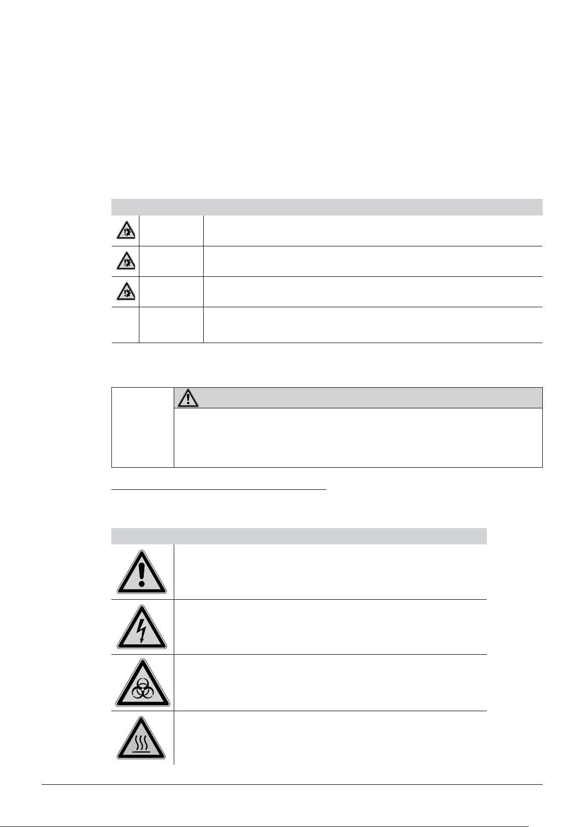
Sign Signal word Definition Risk level
DANGER
Indicates a hazardous situation which, if not avoided, will result in
death or serious injury.
2 Safety
★★★★
WARNING
CAUTION
NOTICE
no
Supplementary safety information symbols may be placed in a rectangular panel on the left to the
signal word and the supplementary text (see example below).
Space for
supplementary
safety
information
symbols.
Table of supplementary safety information symbols
The reference list below incorporates all safety information symbols used in this manual and their
meaning.
Symbol Meaning
Indicates a hazardous situation which, if not avoided, could result
in death or serious injury.
Indicates a hazardous situation which, if not avoided, may result
in minor or moderate injury.
Indicates possible property damage, but no
practices related to personal injury.
SIGNAL WORD
Supplementary text, describing the kind and level of hazard / risk seriousness.
• List of measures to avoid the herein described, hazard or hazardous situation.
• ...
• ...
(property damage only)
★★★☆
★★☆☆
★☆☆☆
12
General warning
Electrical hazard
Biohazard
Hot surface
K-375/376/377 Operation Manual, Version B
Page 13
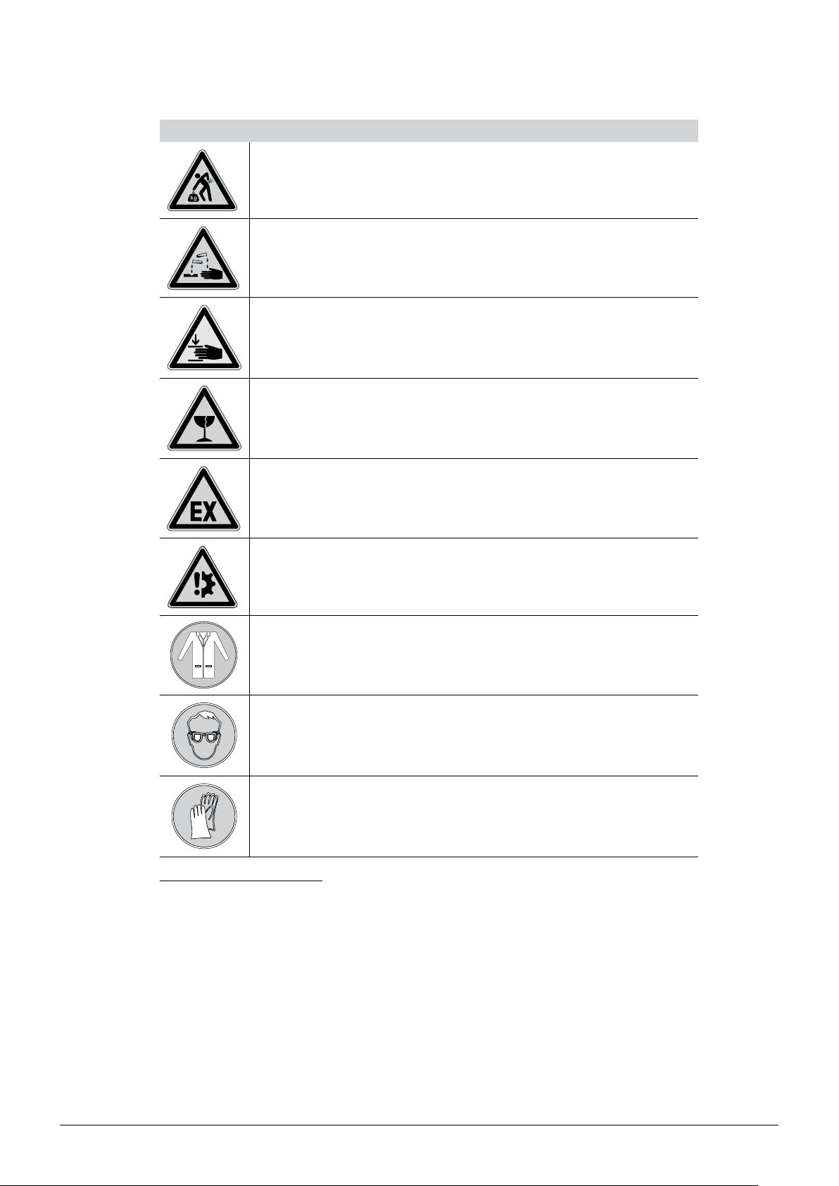
Symbol Meaning
Heavy weight, avoid overexertion
Chemical burns by corrosives
Pinch point. Mechanical hazard.
Fragile components
2 Safety
Explosive gases, explosive environment
Device damage
Wear laboratory coat
Wear protective goggles
Wear protective gloves
Additional user information
Paragraphs starting with NOTE transport helpful information for working with the device / software or
its supplementaries. NOTEs are not related to any kind of hazard or damage (see following example).
NOTE
Useful tips for the easy operation of the instrument / software.
13
K-375/376/377 Operation Manual, Version B
Page 14
2.5 Product safety
The device is designed and built in accordance with current state-of-the-art technology. Nevertheless, risks to users, property, and the environment can arise when the device is used carelessly or
improperly.
The manufacturer has determined residual dangers emanating from the instrument
• if the device is operated by insufficiently trained personnel.
• if the device is not operated according to its proper use.
Appropriate warnings in this manual serve to make the user alert to these residual dangers.
2.5.1 General hazards
The following safety messages show hazards of general kind which may occur when handling the
instrument. The user shall observe all listed counter measures in order to achieve and maintain the
lowest possible level of hazard.
Additional warning messages can be found whenever actions and situations described in this manual
are related to situational hazards.
2 Safety
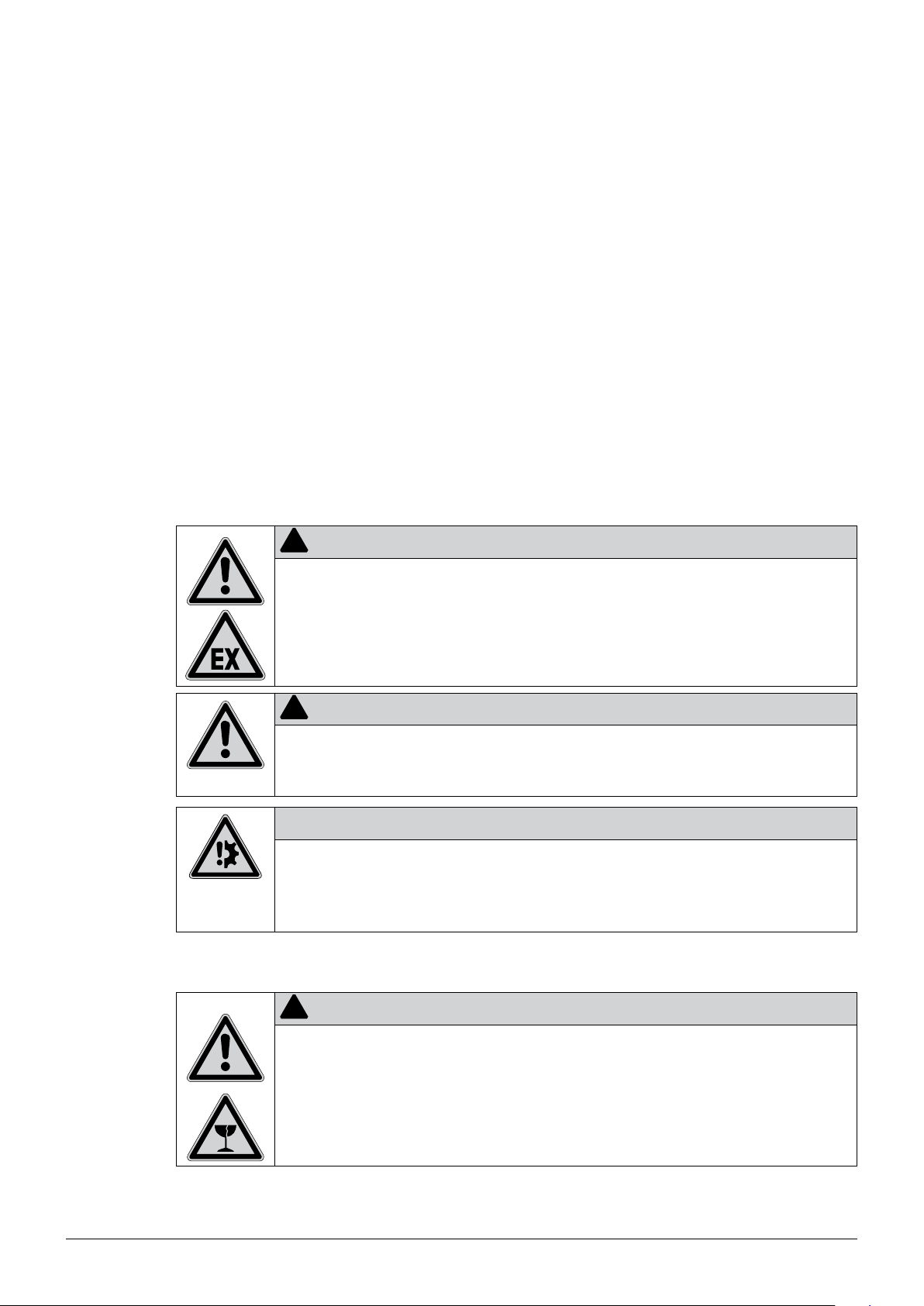
!
Death or serious injuries by use in explosive environments.
• Do not store or operate the device in explosive environments.
• Remove all sources of flammable vapors.
• Do not store chemicals in the vicinity of the device.
!
Risk of minor or moderate cuts by sharp edges.
• Do not touch defective or broken glassware with bare hands.
• Do not touch thin metal edges.
Risk of device damage by liquids or mechanical shocks.
• Do not spill liquids over the device or its components.
• Do not drop the device or its components.
• Keep external vibrations away from the instrument.
2.5.2 Instrument-related hazards
DANGER
CAUTION
NOTICE
14
!
CAUTION
Risk of injury.
• Never touch the surface of the touchscreen with pointed or sharp objects! Otherwise the
screen might get damaged and splinter.
K-375/376/377 Operation Manual, Version B
Page 15
2 Safety
!
CAUTION
Risk of burns by hot surface. Surface temperature exceeds 60 °C.
• Do not touch hot surfaces of the instrument.
!
CAUTION
Risk of pinch point injuries.
• In order to avoid injuries to the hands and fingers the K-376 and K-377 KjelSamplers may not
be manipulated during the moving action of the sampler arm.
!
CAUTION
Risk of burns by hot steam.
• The system works with hot steam. Avoid any contact with hot steam.
!
DANGER
Risk of chemical burns by corrosives.
• Wear laboratory coat, protective gloves and protective goggles at all times.
!
DANGER
Risk of chemical burns by corrosives.
• During operation the sample tube contains either strong acid or strong base. In case the
sample tube brakes, the content of the sample tube is collected in the drip tray on the bottom
of the housing. Wear laboratory coat protective gloves and protective goggles when emptying
the drip tray.
15
K-375/376/377 Operation Manual, Version B
Page 16
2.5.3 Other hazards
Fundamental dangers arise from.
• acids and lye
• flammable gases or solvent fumes in the direct vicinity of the instrument
• damaged glass parts
• insufficient distance between the device and the wall (see chapter 5.1, Installation site)
• burns caused by contact with hot glass parts
• burns caused by contact with steam at the waste-outlet
• defective transfer tube: escape of steam and/or sulfuric acid
2.5.4 Personal protective equipment
Always wear personal protective equipment such as protective eye goggles, protective clothing
and gloves. The personal protective equipment must meet all requirements of all data sheets for
the chemicals used. These instructions are an important part of the K-375, K-376 and K-377 and
must be made available at all times to the operating personnel at the place where the equipment is
deployed. This also applies to additional language versions of these instructions, which can be reordered separately.
2 Safety
!
WARNING
Serious chemical burns by corrosives.
• Observe all data sheets of the used chemicals.
• Handle corrosives in well ventilated environments only.
• Always wear protective goggles.
• Always wear protective gloves.
• Always wear protective clothes.
• Do not use damaged glassware.
16
K-375/376/377 Operation Manual, Version B
Page 17

2.5.5 Built-in safety elements and measures
The KjelMaster K-375 has monitored protective doors which prevent a distillation to start while a
door is open. A running distillation is immediately interrupted when a door is opened. The dosing of
reagents is also immediately stopped.
The sample changers K-376/K-377 have monitored protective shields. Running a sample changer
with opened shield is impossible. For the K-377 only the shield of the tray, that is currently not in use
can be opened.
K-375:
• Protective door: Safety appliance to protect users from burns at the splash protector (distillation
area) which is hot during distillation.
• Protective door sensors: Prevents to start a distillation with the protective doors open and stops
the distillation as soon as a protective door is opened during the process.
• Sample tube sensor: Prevents to start a distillation without a sample tube inserted.
• Service door sensor/switch: Electrical power is disconnected immediately when the service door
is opened, thus preventing electrical shock during maintenance.
K-376:
• Protective shield with sensor/switch: As soon as the shield is opened an alarm sound is triggered
and any movement of the arm is stopped.
2 Safety
K-377:
• Protective shield with sensor/switch: As soon as the shield of the tray in use is opened an alarms
sound is triggered and any movement of the arm is stopped. (The shield of the respective tray
that is not operated can still be opened without any restrictions.)
2.6 General safety rules
Responsibility of the operator
The head of the laboratory is responsible for training his/her personnel.
The operator shall inform the manufacturer without delay of any safety-related incidents which might
occur during operation of the device or its accessories. Legal regulations, such as local, state and
federal laws applying to the device or its accessories must be strictly followed.
Duty of maintenance and care
The operator is responsible for the proper condition of instrument. This includes maintenance, service
and repair jobs that are performed on schedule by authorized personnel only.
Spare parts to be used
Use only genuine consumables and spare parts for maintenance to assure good system performance, reliability and safety. Any modifications of spare parts or assemblies are only allowed with the
prior written permission of the manufacturer.
Modifications
Modifications to the device are only permitted after prior consultation and with the written approval
of the manufacturer. Modifications and upgrades shall only be carried out by an authorized BUCHI
technical engineer. The manufacturer will decline any claim resulting from unauthorized modifications.
17
K-375/376/377 Operation Manual, Version B
Page 18

2 Safety
18
K-375/376/377 Operation Manual, Version B
Page 19
3 Technical data
This chapter introduces the reader to the device specifications. It contains the scope of delivery,
technical data, requirements and performance data.
3.1 Scope of delivery
3.1.1 Basic devices
3 Technical data
Table 3-1: KjelMaster K-375
Product Order number
KjelMaster K-375
with glass splash protector and
potentiometric sensor
(220 – 240 V, 50/60 Hz)
KjelMaster K-375
with glass splash protector and
colorimetric sensor
(220 – 240 V, 50/60 Hz)
KjelMaster K-375
with plastic splash protector and
potentiometric sensor
(220 – 240 V, 50/60 Hz)
KjelMaster K-375
with plastic splash protector and
colorimetric sensor
(220 – 240 V, 50/60 Hz)
Table 3-2: KjelSampler K-376
Product Order number
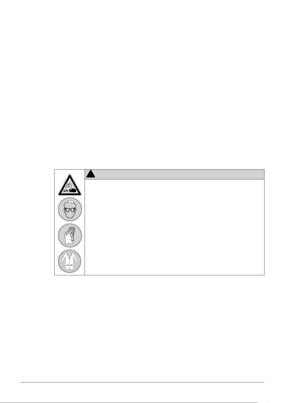
KjelSampler K-376
with one tray
(100 – 240 V, 50/60 Hz)
113751700
113752700
113753700
113754700
113750710
19
Table 3-3: KjelSampler K-377
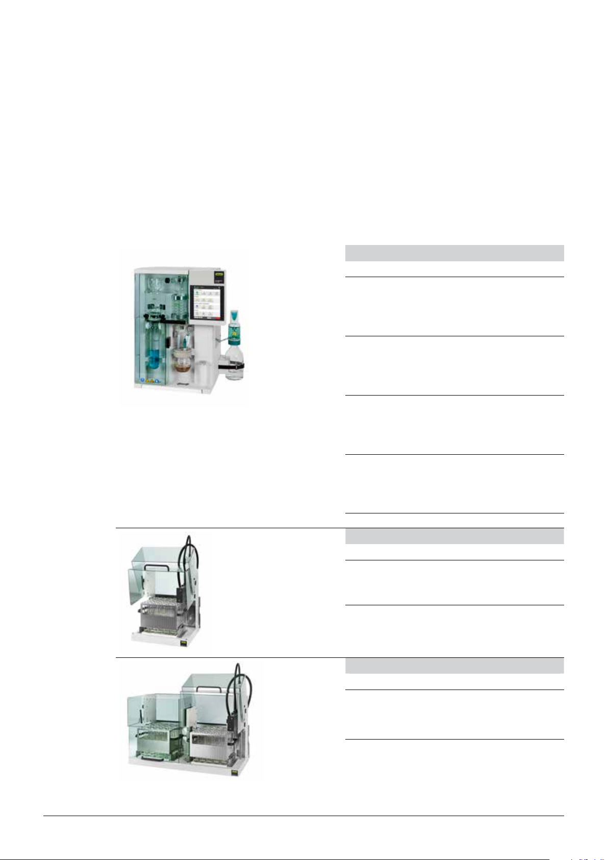
Product Order number
KjelSampler K-377
with two trays
(100 – 240 V, 50/60 Hz)
K-375/376/377 Operation Manual, Version B
113750720
Page 20
3 Technical data
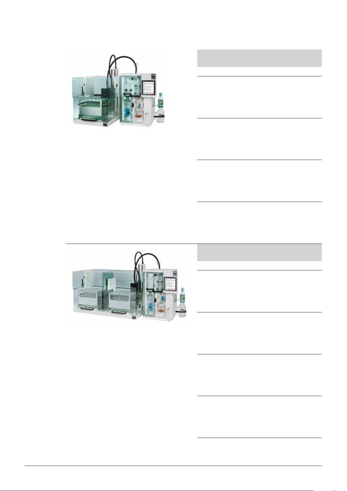
Table 3-4: KjelMaster/Sampler Systems
K-375/K-376
Product Order number
KjelMaster Sampler System K-375/K-376
113751710
K-375 with glass splash protector and
potentiometric sensor
K-375: 220 – 240 V, 50/60 Hz
K-376/K-377: 100 – 240 V, 50/60 Hz
KjelMaster Sampler System K-375/K-376
113752710
K-375 with glass splash protector and
colorimetric sensor
K-375: 220 – 240 V, 50/60 Hz
K-376/K-377: 100 – 240 V, 50/60 Hz
KjelMaster Sampler System K-375/K-376
113753710
K-375 with plastic splash protector and
potentiometric sensor
K-375: 220 – 240 V, 50/60 Hz
K-376/K-377: 100 – 240 V, 50/60 Hz
KjelMaster Sampler System K-375/K-376
113754710
K-375 with plastic splash protector and
colorimetric sensor
K-375: 220 – 240 V, 50/60 Hz
K-376/K-377: 100 – 240 V, 50/60 Hz
Table 3-5: KjelMaster/Sampler Systems
K-375/K-377
Product Order number
KjelMaster Sampler System K-375/K-377
K-375 with glass splash protector and
potentiometric sensor
K-375: 220 – 240 V, 50/60 Hz
K-376/K-377: 100 – 240 V, 50/60 Hz
KjelMaster Sampler System K-375/K-377
K-375 with glass splash protector and
colorimetric sensor
K-375: 220 – 240 V, 50/60 Hz
K-376/K-377: 100 – 240 V, 50/60 Hz
KjelMaster Sampler System K-375/K-377
K-375 with plastic splash protector and
potentiometric sensor
K-375: 220 – 240 V, 50/60 Hz
K-376/K-377: 100 – 240 V, 50/60 Hz
KjelMaster Sampler System K-375/K-377
K-375 with plastic splash protector and
colorimetric sensor
K-375: 220 – 240 V, 50/60 Hz
K-376/K-377: 100 – 240 V, 50/60 Hz
113751720
113752720
113753720
113754720
20
K-375/376/377 Operation Manual, Version B
Page 21
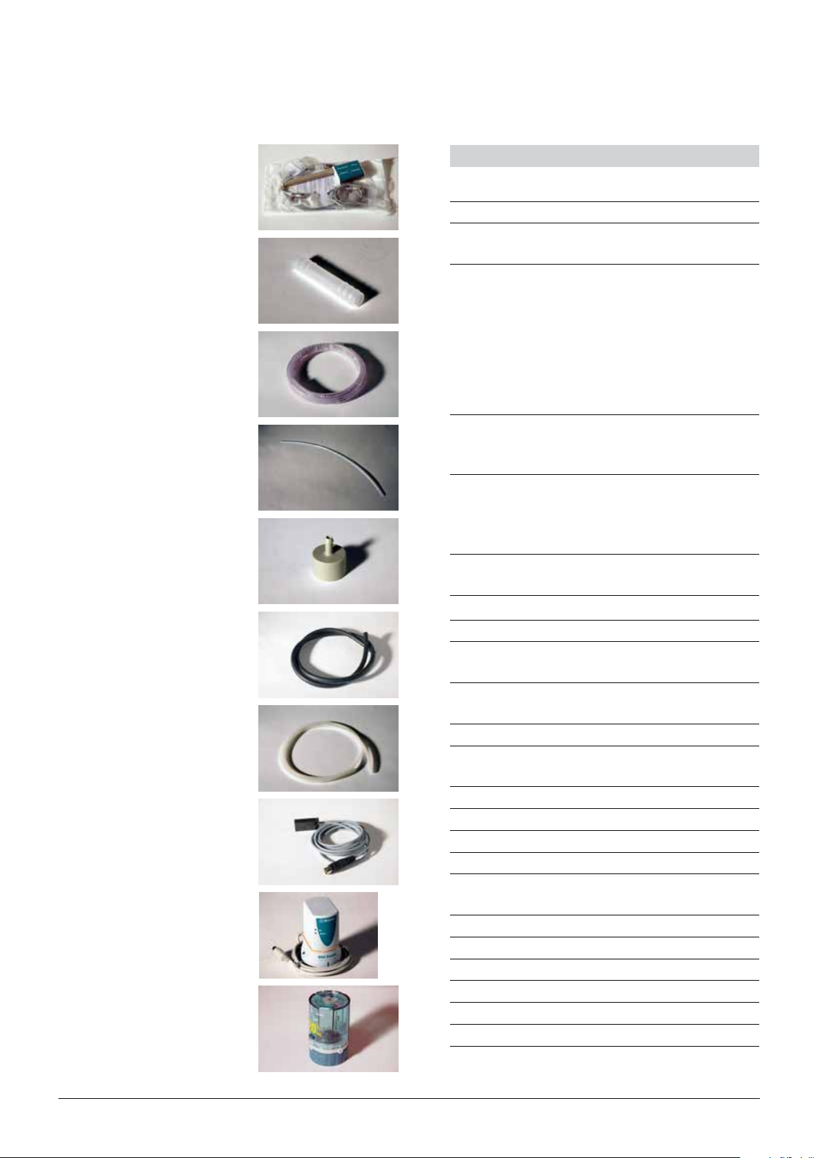
3.1.2 Standard accessories for K-375
11057410
43178
43185
43407
49151
3 Technical data
Table 3-6: Standard accessories for K-375
Number
of pieces
Product Order number
1 Pair of glass tongs 02004
1 Connection cable RJ45 length
44989
2 m
1 Mains cable of the following
types
Type CH 10010
Type Schuko/Japan 10016
Type GB 17835
Type AUS 17836
Type USA 33763
1 pH electrode
or (according to purchase order)
colorimetric sensor
1 Indicator according to Sher,
11056842
11057410*
003512
100 mL
(if device version with colorimetric sensor is shipped)
1 Buffer set pH 4 and pH 7
43188
(3 x 20 mL each)
1 KCI electrolyte, sat. , 250 mL 11059759
43457
11058157
11055914
11056835
11056836
1 Hose connector in line 11–13 43178*
1 Hose chemical supply, Nyflex,
43185*
length 6 m, Ø 5/10 mm
3 Suction tube to tanks, FEP,
43407*
length 580 mm
1 Connection grommet 49151*
2 Hose waste drain, EPDM,
43457*
L = 1.8 m, ø 11/18 mm
5 Clamp D15.6 49167
1 Silicone hose ø 8 mm/12x1.8m 11058157*
1 Clamp D12.8 43297
1 Y-piece ø12 mm 11058358
1 Cooling water hose complete:
37780
G 3/4”, G 1/2”, L = 1.5 m
3 Clamp D11.9 43841
2 O-ring 190.1 x 3.53 EPDM 75 49676
2 O-ring 247.2 x 3.53 EPDM 11058241
4 Level sensor 11055914*
1 Laboratory vessel 53203
1 Dosino 800 11056835*
1 Dosing unit 11056836*
21
K-375/376/377 Operation Manual, Version B
Page 22

3 Technical data
43203
11058252
Table 3-6: Standard accessories for K-375
(continued)
11059802
11057779
3.1.3 Standard accessories for K-376
43482
11057711
Number
of pieces
Product Order number
1 Gauge sample tube holder 11059802
2 Tank 10 L, without caps 43410
2 Cap for 10 L tank, large 25869
4 Cap for 10 L and 20 L tank, small 43477
4 Tank labels 43434
2 Tank 20 l, without caps 43408
2 Cap for 20 L tank, large 43478
1 Distance holder buret tip 43203*
1 Mini gender changer 43108
1 Weighing boat 40444
4 EPDM sealing for tanks 43048
1 Open end spanner 11058252*
1 Tool SVL 22 11057779*
Table 3-7: Standard accessories for K-376
Number of
pieces
1 K-376/K-377 cable RS232
Product Order number
43920
(crossed)
1 Sample tube 300 mL 3904
1 Sample tube 500 mL 26128
1 Clamp ring 43238
1 Hose clamp 22352
1 Fastener for transfer tube 43482*
6 Sample tubes (set of 4), 300 mL 37377
1 Express rack, 4 places 11057711*
1 Rack complete, 20 places 11059831*
22
11059831
11058240
1 Mains cable of the following
types
Type CH 10010
Type Schuko/Japan 10016
Type GB 17835
Type AUS 17836
Type USA 33763
1 Test gauge for sample tubes 11058240
K-375/376/377 Operation Manual, Version B
Page 23
3.1.4 Standard accessories for K-377
11058240
3 Technical data
Table 3-8: Standard accessories for K-377
Number of
pieces
1 K-376/K-377 cable RS232
Product Order
number
43920
(crossed)
2 Sample tube 300 mL 3904
1 Sample tube 500 mL 26128
1 Clamp ring 43238
1 Hose clamp 22352
1 Fastener for transfer tube 43482
12 Sample tubes (set of 4), 300 mL 37377
2 Rack complete, 20 places 38621
1 Mains cable of the following types
Type CH 10010
Type Schuko/Japan 10016
Type GB 17835
Type AUS 17836
Type USA 33763
1 Test gauge for sample tubes 11058240
Table 3-9: Operation Manuals and Quick Guides
Product Order number
Operation Manual:
English 11593514
German 11593515
French 11593516
Italian 11593517
Spanish 11593518
Chinese 11593519
Japanese 11593520
23
K-375/376/377 Operation Manual, Version B
Page 24
3.1.5 Optional accessories K-375
43333
43390
3 Technical data
Table 3-12: Optional accessories K-375
Product Order number
Sample tubes (set of 4), 300 mL 37377
Sample tube 500 mL 26128
Sample tubes (set of 4), 500 mL 43982
Pair of glass tongs 02004
Receiving vessel 340 mL 43333*
Receiving vessel 420 mL 43390*
Devarda splash protector 43335
Tanks without level sensors, including caps
10 L chemicals 43468
10 L waste 43470
20 L chemicals 43469
20 L waste 43471
11056851
Level sensor 11055914
O-ring level sensor (10 L tank) 49676
O-ring level sensor (20 L tank) 11058241
Spectrosense 610 nm with cable 11057410
Buffer solution pH 4, 1000 mL 26321
Buffer solution pH 7, 1000 mL 26322
Indicator according to Sher, 100 mL 03512
Temperature sensor for titrator 11056851*
Dosing unit (for back titration) 11056836
Motor for dosing unit 11056835
Sample tube holder for 4 sample tubes,
16951
500 mL each
IQ/OQ Package K-375 (English) 11058677
IQ/OQ Package K-375/K-376/K-377
11058678
(English)
Repeating OQ Package K-375 (English) 11058679
Repeating OQ Package K-375/K-
11058680
376/K-377 (English)
24
K-375/376/377 Operation Manual, Version B
Page 25

3.1.6 Optional accessories K-376/K-377
3 Technical data
Table 3-14: Optional accessories for K-376/K-377
Product Order number
Stand for rack 11058659
Sample tubes (set of 4), 500 mL 43982
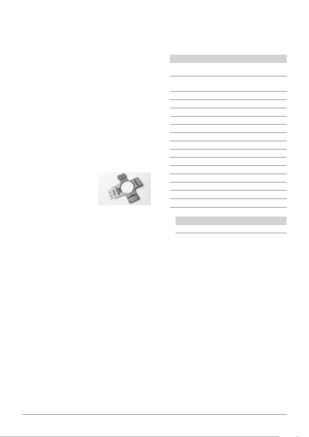
Rack for 12 sample tubes, 500 mL 43970*
Retainer plate (holds tubes firmly in rack
43970
for machine washing)
Set of 10 boiling rods for digestion of
samples with tendency of boiling retardation (alternative for boiling chips)
Sample tubes (set of 4), 300 mL 37377
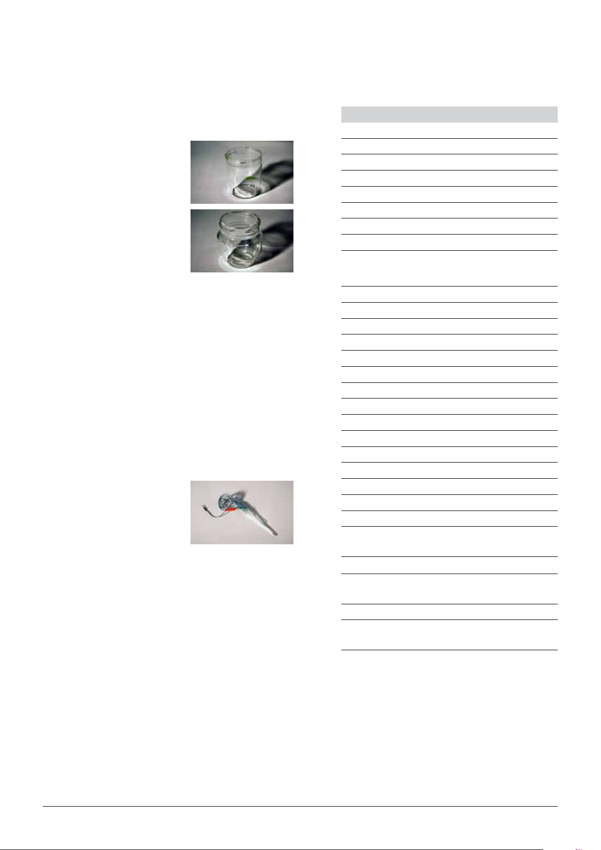
Dip tube with cross-slot for soil/stone
containing samples
Glassfinger for sample tubes
for soil samples
38559
43087
47845
48638
25
K-375/376/377 Operation Manual, Version B
Page 26

3.2 Technical data overview
3.2.1 Technical data KjelMaster K-375 and KjelSampler K-376/K-377
Table 3-15: Technical data
KjelMaster K-375 KjelSampler K-376 KjelSampler K-377
Connection voltage 220 – 240 VAC ±10% 100 – 240 VAC ± 10 % 100 – 240 VAC ± 10 %
Frequency 50/60 Hz 50/60 Hz 50/60 Hz
Power consumption max. 2.2 kW max. 150 W max. 150 W
Current consumption (230 V) 9.5 A 650 mA 650 mA
Weight 32 kg 40 kg
3 Technical data
64 kg
(without rack and sample
tubes)
Dimensions (W x H x D) 458 x 670 x 431 mm 505 x 750* x 655
* 1000 mm height
required to allow free
movement of the sampler
arm
(without rack and sample
tubes)
1015 x 750** x 655
**1250 mm height
required to allow free
movement of the sampler
arm
Interfaces RS232 RS232 RS232
Recovery rate > 99.5 % (1 – 200 mg N)
Reproducibility (RSD) < 1 %
Measuring range 0.1 – 200 mg N
Environmental conditions
Temperature
Altitude
Humidity
for indoor use only
+ 5 °C to + 40 °C
up to 2000 m above sea level
maximum relative humidity 80 % for temperatures up to 31 °C, decreasing linearly to
50 % relative humidity at 40 °C
Mains connection Device plug C14 Device plug C14 Device plug C14
Overvoltage category II II II
Pollution degree 2 2 2
Approval CE/CSA CE/CSA CE/CSA
3.2.2 Technical data titrator
The following sensors can be connected to the titrator:
• combined pH glass electrode
• optical sensor with measuring range between 50 and 1000 mV (max. 1200 mV)
• temperature measuring sensor for Resistance Thermometer Pt 1000, connection: 2 x 4 mm
sockets and 1 x 2 mm socket
Dosing accuracy:
According to DIN EN ISO 8655, Part 3, or better
Typical accuracy: Systematic error max. ± 30 µL
26
K-375/376/377 Operation Manual, Version B
Page 27

3 Technical data
Measuring input: pH/mV input with 12 bit transducer for accurate resolution during the titration
Connection:
Measuring range Display resolution Accuracy* without sensor Input resistance (Ω)
pH 0…14 0.01 0.05 ±1 digit > 5·10
mV –1400 ... +1400 0.1 2 ±1 digit > 5·10
Measuring range Display resolution Accuracy* without sensor
T [°C] –30…115 0,1 0,5 K ±1 digit
*Accuracy:
Indicated in terms of measuring incertainty with a confidence of 95%. In addition the measuring uncertainty of the sensor has to be taken into account as well. For pH electrodes e.g.: ∆ pH= 0.012...0.03
according to DIN 19 266, Part 3.
3.3 Titration solution
The amount of sample and the concentration of the titrant should be optimized, so that the titrant
volume is between 3 and 17 mL (buret volume: 20 mL).
Table 3-16: Nitrogen expected
N-amount N-content Sample size Titrant Titrant concentration Titrant volume
5 mg N 0.5 % N 1 g
50 mg N 5 % N 1 g
100 mg N 10 % N 1 g
100 mg N 10 % N 1 g
200 mg N 20 % N 1 g
200 mg N 20 % N 1 g
electrode socket according to DIN 19 262 or BNC socket and reference electrode 1 x 4 mm socket
12
12
H2SO4 0.01 mol/L
H2SO4 0.1 mol/L
H2SO4 0.25 mol/L
H2SO4 0.5 mol/L
H2SO4 0.5 mol/L
H2SO4 1 mol/L
17.8 mL
17.8 mL
14.3 mL
7.1 mL
14.3 mL
7.1 mL
Table 3-17: Protein expected
P-content P-factor N-content Sample size Titrant Titrant concentration Titrant volume
1 % P 6.25 0.16 % N 2 g
2 % P 6.25 0.32 % N 1 g
5 % P 6.25 0.80 % N 2 g
10 % P 6.25 1.6 % N 2 g
10 % P 6.25 1.6 % N 2 g
20 % P 6.25 3.2 % N 2 g
50 % P 6.25 8.0 % N 2 g
H2SO4 0.01 mol/L
H2SO4 0.01 mol/L
H2SO4 0.1 mol/L
H2SO4 0.1 mol/L
H2SO4 0.25 mol/L
H2SO4 0.25 mol/L
H2SO4 0.5 mol/L
11.4 mL
11.4 mL
5.7 mL
11.4 mL
4.6 mL
9.1 mL
11.4 mL
General recommendation
The correction factor for self prepared solutions is called titer.
The use of standardized titration solutions make a titer determination unnecessary.
Exact titrant concentration = concentration x titer
The titer of the titrant must be known. In case, it is unknown, it must be determined.
Example: Exact titrant concentration = 0.100 mol/L x 0.998
27
K-375/376/377 Operation Manual, Version B
Page 28

3.4 Information on type plate
a Device type code
b Serial number
3 Technical data
c Supply voltage range/type
d Frequency of supply voltage
e Nominal power rating
f Year of manufacture
28
K-375/376/377 Operation Manual, Version B
Page 29

3.5 Reference substances
Table 3-18: Reference substances
Name Purity % N theoretical
Ammonium
99.5 12.18 0.2 g c(H2SO4) = 0.1 mol/L No
dihydrogen
phosphate
Glycine 99.7 18.66 0.2 g c(H
Phenylalanine 99.0 8.47 0.3 g c(H2SO4) = 0.1 mol/L Yes
Ammonium
99.5 21.21 0.2 g c(H2SO4) = 0.1 mol/L No
sulfate
Tryptophan 99.0 13.72 0.2 g c(H
Acetanilide 99.0 10.36 0.2 g c(H2SO4) = 0.1 mol/L Yes
3.6 Materials used
(100 % purity)
Recommended
sample size
3 Technical data
Recommended titrant concentration Digestion necessary
2SO4) = 0.1 mol/L Yes
2SO4) = 0.1 mol/L Ye s
3.6.1 Titrator module and dosing unit
Table 3-19: Materials on the titrator
part Material designation
Housing sheet steel
NOTE
For the materials of the Dosing Unit, please refer to its manual which is delivered together with
dosing unit.
3.6.2 K-375
Table 3-20: Material on the K-375
Part Material Material code
Housing Polyurethane PUR/UL VO
Glass parts Borosilicate glass 3.3 DIN/ISO 3585
Insulation steam generator Ceramic fiber Multitherm 550
Steam generator housing Stainless steel 1.4301
Protective door Polymethyl methacrylate PMMA
Seal ring Chlorosulfonyl polyethylene elastomer CSM
29
K-375/376/377 Operation Manual, Version B
Page 30

3.6.3 K-376/K-377
Table 3-21: Material on the K-376/K-377
Part Material Material code
Housing (mounting plate) Steel sheet St 12 ZE 1.0330
Housing (casing-below) Stainless steel 1.4301 (L 314)
Housing (top cover) Alu-sheet AlMgSi1
Guide express rack PP PP
Coating Polyester/Epoxy PEP 31
Protective shield Polymethyl methacrylate/Alu PMMA/Alu
Drip tray Polypropylene PP
Housing y-axle Alu-sheet AlMgSi1
End cap y-axle POM POM
Dip tube PVDF PVDF
Sealing cap EPDM EPDM
Transfer hose linear PTFE PTFE
Steam tube Silicone/polyester MQ-PU
Protective hose PP PP
Hose chain PA PA
3 Technical data
30
K-375/376/377 Operation Manual, Version B
Page 31

4 Description of function
This chapter explains the basic principle of the instrument, shows how it is structured and gives a
functional description of the assemblies.
The KjelMaster K-375 is dedicated to Kjeldahl and Devarda nitrogen deter mination including potentiometric or colorimetric titration.
Automation of Kjeldahl determination is possible with the KjelSampler K-376/K-377.
4.1 Device overview
4 Description of function
a KjelMaster K-375
b KjelSampler K-376
c Protective shield
d Rack with sample tubes
e Handle for protective shield
f Transfer hose
g Splash protector
h Sample tube bracket
Fig. 4.1: Device overview
i Sample tube
j Protective door
k Condenser
l Receiving vessel
m Touch screen with display
n pH electrode or optical sensor
o Service door
p External buret
NOTE
The main switch of each device can be found on the rear right side of the housing.
31
K-375/376/377 Operation Manual, Version B
Page 32

4.1.1 Opening the service door
The service door is secured with a sensor/switch: Electrical power is disconnected immediately when
the service door is opened, thus preventing electrical shock during maintenance.
To open the the service door for maintenance proceed as follows:
4 Description of function
To open the service door,
• pull the door lock ① upwards
• open the door ②
Fig. 4.2: Opening the service door
32
K-375/376/377 Operation Manual, Version B
Page 33

4 Description of function
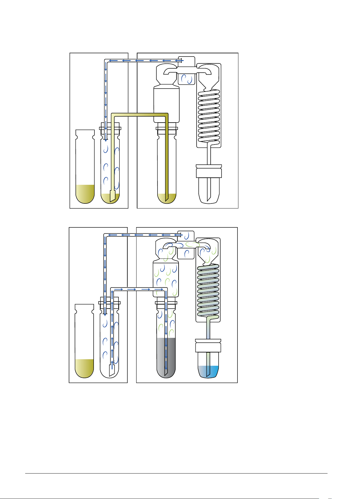
4.2 Functional principle of Sampler System K-375 with K-376 or K-377
a K-376/K-377
b K-375
c Sample tube
d Dip tube
e Splash protector
f Steam generator
g Condenser
h Distillate outlet tube
i Receiving vessel
Fig. 4.3: Functional principle of the K-375 with K-376 or K-377
The sampler arm with dip tube is positioned in a sample tube in the K-376/K-377. The steam
generator of the K-375 generates steam which is lead into the sample tube in the K-376/K-377 via
the steam hose.
The steam presses the sample into the dip tube, so that the sample is transferred into the sample
tube in the K-375 via the transfer hose.
Water and sodium hydroxide is dosed into the sample tube in the K-375. Then steam is introduced
to drive out ammonia. The ammonia evaporates into the splash protector and condensates in the
condenser.
Boric acid is dosed into the receiving vessel, where the condensated ammonia is collected and finally
titrated.
During the entire distillation process, steam is transferred via the sample tube of the K-376/K-377 to
the sample tube of the K-375, thus ensuring a thorough cleaning of the sample tube and the transfer
hose.
33
K-375/376/377 Operation Manual, Version B
Page 34
4 Description of function
Fig. 4.4: Sample transfer principle
Fig. 4.5: Steam transfer during distillation
34
K-375/376/377 Operation Manual, Version B
Page 35

4.3 Standby function
4 Description of function
Press the key READY to start heating the steam
generator.
Press the key STANDBY to stop heating the
steam generator.
Fig. 4.6: Status view
After 30 minutes without operation, the heating of the steam generator is automatically turned off.
In this case „Standby“ is displayed on the Status view.
To activate the device press the READY key. The steam generator will need 120 seconds for heating
up to the operating temperature.
4.4 System preparation
4.4.1 Preheating
The glass parts of the distillation system have to be preheated prior to analysis. This is done by
means of a clean and empty sample tube. It is recommended to perform a preheating, when the
glass (splash protector) has cooled down. The preheating time is predefined and can not be adapted.
4.4.2 Priming
Priming is used to prepare the entire system. This preparation procedure includes distillation and
titration with a clean and empty sample tube. It is recommended to perform a priming at least once a
day, before starting analysis. The priming method can be modified.
4.4.3 Cleaning
At the end of a day, the system should be rinsed thoroughly by performing a cleaning procedure. The
splash protector and the condenser are rinsed with water to remove sodium hydroxide residues. With
regular cleaning, the lifetime of the glass parts can be extended. The cleaning method is predefined,
but can be modified and adapted to the size of the sample tube.
4.4.4 Aspiration
With this procedure residues in the sample tube and in the receiving vessel can be aspirated.
For more details see also chapter “6.6.1 System preparation”.
35
K-375/376/377 Operation Manual, Version B
Page 36

4.5 Distillation and titration
4.5.1 Distillation Mode
Automatic – IntelliDist
This mode eliminates errors caused by a cooled instrument. The countdown of the set distillation
time only starts after operating temperature is attained. With single samples or sample list measurements this mode guarantees result accuracy from the very first run.
Fixed Time
The countdown of the set distillation time starts immediately with the start of the distillation process.
This setting is recommended when a sample changer is used for the analysis of samples in a rack (or
sequence).
4.5.2 Titration Type
The built-in titrator is fully controlled via the K-375 software. It is not possible to use the titrator
without the KjelMaster K-375. It can be used for boric acid or back titration. The measuring mode
can be determined as endpoint or startpoint titration by defining the method in the K-375. The software of the K-375 allows to choose between standard and online titration. The endpoint detection
can be performed either with a potentiometric sensor or a colorimetric sensor in combination with a
color-indicator.
4 Description of function
Boric Acid Titration
Boric acid is used as receiving solution to capture the nitrogen carried over as ammonia during the
steam distillation. The subsequent endpoint titration is performed with an acid titration solution. This
titration type is easy to carry out and does not require an accurate dosage of the boric acid.
Back Titration
The receiving solution is a standardized acid of which an accurate volume is dispensed into the
receiving vessel. After collecting the ammonia the excess acid is titrated with a basic titration solution. If the use of boric acid has to be avoided the back titration is the procedure of choice.
4.5.3 Sensor Type
Potentiometric
Potentiometric electrodes for the pH measurement are commonly used and allow both boric acid
and back titrations. They need regular calibration with buffers and are the most cost-effective solution
for end point titrations.
Colorimetric
Optical sensors used for colorimetric titrations detect the color change of an indicator at the equivalence point of the titration curve. The indicator has to be added to the receiving solution. These
sensors do not require calibration, have an extended life time but are more expensive.
4.5.4 Titration Mode
Standard
In the standard mode the distillation and titration are performed sequentially. First the distillation is
completed before the titration starts.
Online
With this mode activated the titration will start while the distillation is still in progress. The start time of
the titration depends on the pH value and is determined automatically. The online mode can only be
used with potentiometric titrations. It helps optimize the speed of measurements as it saves time.
36
K-375/376/377 Operation Manual, Version B
Page 37

4.5.5 Measuring Mode
Startpoint pH
The device measures the pH of the boric acid before the distillation is started and uses it later on as
enpoint for the titration. If the boric acid used as receiving solution is not adjusted to pH 4.65 the
startpoint mode is recommended.
Endpoint pH
The set value, normally 4.65, is used as endpoint for the titration. The boric acid has to be adjusted
to pH 4.65 before starting sample measurements. This mode is more accurate and yields the highest
accuracy.
4.5.6 Titration Algorithm
Normal
This algorithm is the most accurate one and is recommended for samples with low nitrogen content
(below 1 mg) and for the use of highly-concentrated titration solutions (e.g. 0.5 N acids).
Optimal
The best ratio between accuracy and process speed is achieved with this algorithm.
4 Description of function
4.5.7 Determination Mode
Standard
In the majority of cases it is necessary to digest samples to make the nitrogen accessible to steam
distillation. Whenever digested samples are analyzed the standard determination mode is used.
Direct Distillation
A small number of applications allow freeing the nitrogen via direct steam distillation without requiring
a digestion. In such a case the direct distillation mode needs to be activated.
37
K-375/376/377 Operation Manual, Version B
Page 38
4.6 Different methods
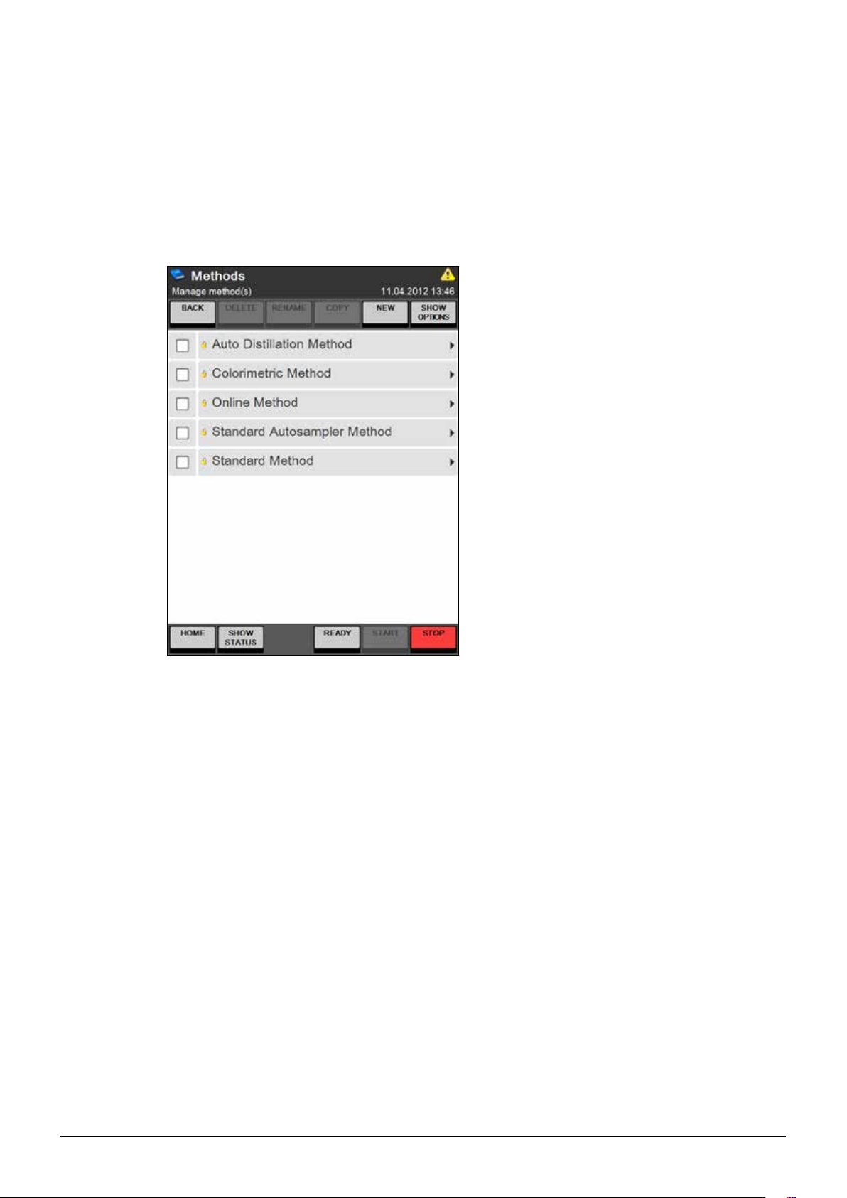
BUCHI standard methods are stored in the instrument. All BUCHI methods are “read only“, but it is
possible to copy and save them under a different name as an editable customer method.
All methods are listed in alphabetical order, customer methods are first, followed by the “read only”
BUCHI methods (marked with a small yellow lock).
4 Description of function
Fig. 4.7: Methods screen
38
K-375/376/377 Operation Manual, Version B
Page 39

4.7 Blank values
The K-375 differentiates between blanks and control blanks. Blanks are performed to correct minimal
contamination of chemicals on sample determination (sample and reference substance).
Control blanks are performed to check the determination process for cross contaminations and are
not used for calculation.
The determination and the definition of blank values is described in chapter 6 Operation.
4.7.1 Blanks
It is recommended to run blank values with exactly the same method as the subsequent samples.
The blank values may vary, depending on the receiver solution (e.g. concentration of the boric acid,
amount of indicator added, pH value set), the concentration of the titration solution, and the purity of
chemicals.
It is recommended to perform blank values, if:
• Fresh chemicals are used or
• Before starting determination in order to check the system.
If a blank value is activated for calculation, it remains active, until another blank value is activated.
4 Description of function
4.7.2 Control blanks
A control blank enables to check for crosscontamination, e.g. in the middle of a rack, without
affecting the calculation of the following samples.
Example:
Determination of
3 blanks, 6 samples, 1 control blank, 10 samples in a 20-position rack.
All samples are calculated with the mean value of blank 1-3. The control blank allows to check the
system without interruption.
4.8 Reference substances
Reference substances are substances with known nitrogen content and serve to check the performance of the system and the application.
It is recommended to analyze reference substances regularly. For information on reference
substances, see chapter 3, Technical data.
A check of the K-375 without digestion is done with a standardized ammonium salt (e.g. ammonium
di-hydrogen phosphate).
In order to check the entire Kjeldahl process (including digestion), standardized amino acids are used
(e. g. Glycine).
The determination of reference substances is done like a normal sample determination (Sample type:
“Reference substance”) as single sample, sample list or a sequence. See Chapter “6.6 Determina-
tion” for details.
4.9 Result Groups
Each result of a sample determination can be assigned to a group, e.g. the results of samples taken
from the same batch/lot, place, at the same day, etc. can be assigned to the same result group.
All results in the same group are treated the same way regarding sample printout and export of data.
39
K-375/376/377 Operation Manual, Version B
Page 40
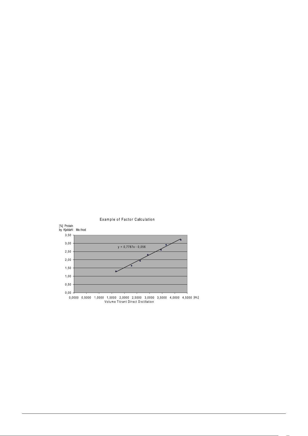
4.10 Explanation of alkaline direct distillation
As an example, the protein content in milk samples can be determined by direct distillation. This
quick method is based on the fact that milk releases ammonia when boiled in an alkaline solution.
Most of this ammonia is produced by the rapid hydrolysis of proteins containing glutamine and asparagine. This decomposition is completed within a few minutes. An additional quantity of ammonia,
although small, is released through the complete transformation of other amino-acids. This second
reaction occurs very slowly however, and does not interfere with the quick method. This fact permits
an experimental determination of the ratio of total nitrogen or protein to ammonia nitrogen which is
released by boiling in an alkaline solution. Once the resulting conversion factor is determined, a series
of analysis can be carried out for control purposes without the time-consuming digestion step. The
overall analysis is reduced to the following steps:
• Sample addition
• Dilution
• Alkalisation
• Distillation
• Titration
• Calculation
A determination can be completed in approx. 10 minutes according to this procedure. All working
conditions chosen for the experimental determination of the conversion factor must be strictly
adhered to during sample measurements.
For details on the application procedure, please contact your local BUCHI representative.
Determination of the conversion factor and the regression factor:
4 Description of function
Fig. 4.8: Example of factor calculation
40
K-375/376/377 Operation Manual, Version B
Page 41

4 Description of function
Factors of above Example
Conversion Factor = 0.7787; Regression Factor = -0.055.
NOTE
Milk samples with a reduced protein content are obtained by dilution with distilled water.
Calculation:
Calculation of the protein content after factor determination.
g protein/100 mL = (V
sample-Vblank )xConv. Fact.+Reg. Fact.
Vsample = Volume Titrant for sample determination in mL
Vblank = Volume Titrant for blank determination in mL
Conv. Fact. = Conversion factor for direct distillation
Reg. Fact. = Regression factor for direct distillation
41
K-375/376/377 Operation Manual, Version B
Page 42

4 Description of function
42
K-375/376/377 Operation Manual, Version B
Page 43
5 Putting into operation
This chapter describes how the device is installed and gives instructions on initial startup.
NOTE
Inspect the device for damages during unpacking. If necessary, prepare a status report immediately
to inform the postal company, railway company or transportation company.
Keep the original packaging for future transportation.
!
CAUTION
Heavy weight, avoid overexertion.
• Due to the heavy weight of the devices at least two people are required for taking the KjelMaster K-375 or the KjelSamplers K-376 out of their corresponding packaging. Watch your
fingers when putting the device down.
• For the K-377 at least three people are required for taking the device out of the corresponding packaging. Watch your fingers when putting the device down.
5 Putting into operation
5.1 Installation site
The device must be set-up on a stable, clean and level surface.
For safety reasons the distance between the back of the device and the wall or to another object
must be at least 30 cm. No containers, chemicals or other objects must be located behind the instrument.
The KjelSampler K-376 or K-377 is set-up on the left side of the KjelMaster K-375 with a space of
approximate 10 cm. Make sure that the back of the KjelSampler is not in contact with anything, e.g.
hoses, etc.
All devices must be set up in such a way that the main switches and the mains plugs are easily
accessible at all times.
Risk of device damage.
• The sampler arm of the Autosampler K-376/K-377 must have enough space in height for
Heavy weight, avoid overexertion.
• At least two people are required for carrying the KjelSampler K-376 or the KjelMaster K-375
• At least three people are required for carrying the KjelSampler K-377 due to the heavy
NOTICE
movement.
!
CAUTION
due to the heavy weight of the devices. Watch your fingers when putting the devices down.
weight of the device. Watch your fingers when putting the device down.
43
K-375/376/377 Operation Manual, Version B
Page 44

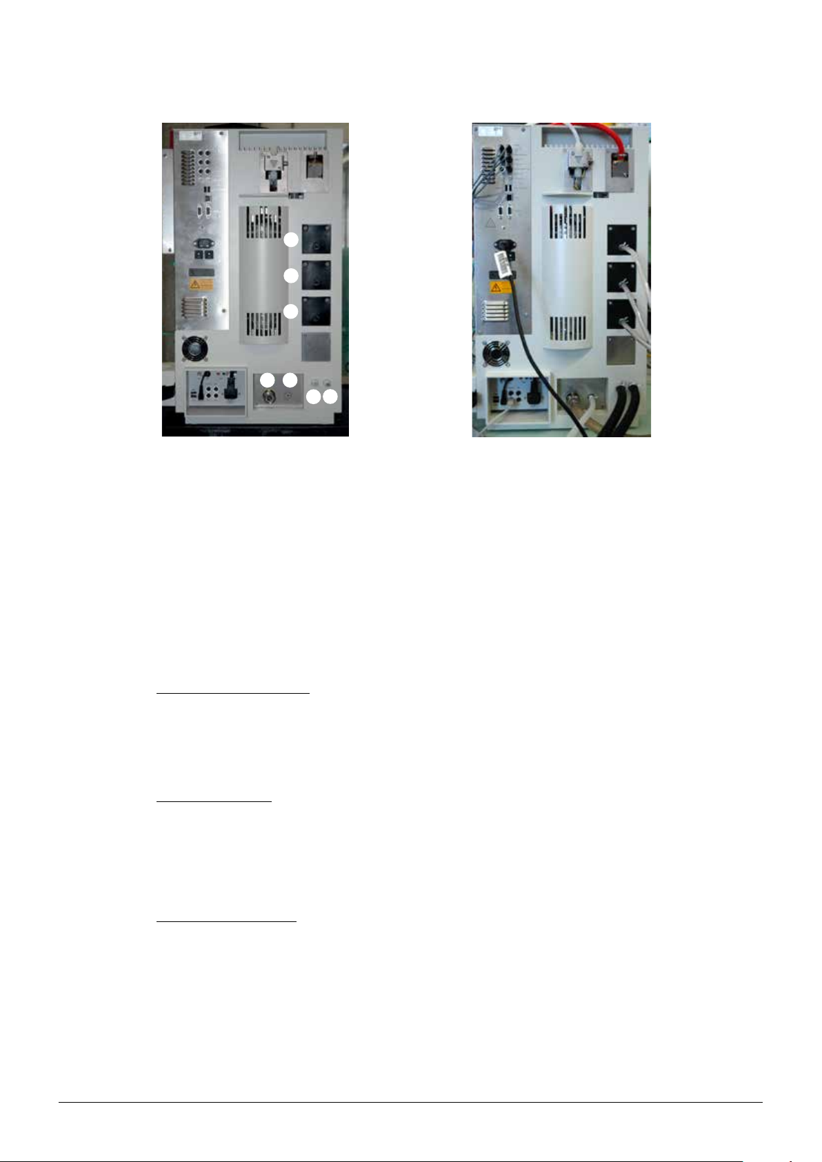
5.2 Electrical connections
5.2.1 Connections of the K-375
5 Putting into operation
a Power connection K-375
b RS232 connection to K-376/K-377
c RS232 connection to external bal-
ance
d LAN connection
e USB connection for external printer
f USB connection for bar code reader
g Connectors for level sensors
Fig. 5.1: Electrical connections of the K-375
NOTICE
Risk of device damage by wrong voltage.
• Make sure that the voltage on the socket corresponds to the voltage given on the type plate
of the instrument.
• Always connect the device to an earthed socket. External connections and extension cables
must be provided with an earthed conductor lead (3-pole couplings, cable or plug equipment)
as the mains lead has a molded plug, thus avoiding risks due to inadvertent defective wiring.
• Make sure that no electric sparks form in the device or its surroundings as they might
damage the instrument.
h Fuses (2 x 10A)
i Connector for dosing unit (Acid)
j Connector for additional dosing unit (Base)
k Additional USB-ports
l Connectors for colorimetric sensor (Ind. and Pwr. Col.) or pH electrode
(Ind. only)
m Connectors for temperature sensor
On the K-375 instrument
• Connect the power cable to the power connection
a.
• Connect the level sensors to the corresponding connectors g.
NOTE
Unlike the level sensors for the storage tanks of H
20, NaOH and H3BO3, the presence of the level
sensors for the waste containers has to be indicated within the software! (See section “Peripherals”
in chapter 6.9.1)
44
K-375/376/377 Operation Manual, Version B
Page 45

• Connect the dosing unit for the acid to connector i.
• Connect the RS232 cable to the sampler (if present) to the corresponding connector b.
• Connect any additional perihperals according to the description in figure 5.1.
5.2.2 Connections of the K-376/K-377
5 Putting into operation
(left rear side of the housing)
(right rear side of the housing)
a Power switch K-376/K-377
b Power connection K-376/K-377
c Fuses (2 x 3A)
Fig. 5.2: Electrical connections of the K-376/K-377
d RS232 connection to K-375
e Toggle switch (see chapter 8.3)
NOTICE
Risk of device damage by wrong voltage.
• Make sure that the voltage on the socket corresponds to the voltage given on the type plate
of the instrument.
• Always connect the device to an earthed socket. External connections and extension cables
must be provided with an earthed conductor lead (3-pole couplings, cable or plug equipment)
as the mains lead has a molded plug, thus avoiding risks due to inadvertent defective wiring.
• Make sure that no electric sparks form in the device or its surroundings as they might
damage the instrument.
On the K-376/K-377 sampler
• Connect the power cable to the power connection b
• Connect the cable to the K-375 device to the RS232 connector d
45
K-375/376/377 Operation Manual, Version B
Page 46

5.3 Transfer connection K-376 (K-377) – K-375
The transfer connection between the K-375 and the K-376 or K-377 sampler consists of two hoses,
the white transfer hose and the red steam hose.
Both hoses have to be connected to the K-375 as well as to the sampler (K-376 or K-377) and
secured with hose clamps. The K-376 is delivered with both hoses premounted to the device.
!
WARNING
Serious chemical burns by corrosives. Risk of burns by hot steam.
• Never operate the K-375 together with a sampler while the sample transfer and steam hoses
are missing, defective, or incorrectly mounted.
• Make sure there is always enough room for a free movement of the sampler arm – if the
sampler arm collides with any object during movement, the transfer hose and/or the steam
hose may break!
5 Putting into operation
5.3.1 Connecting the K-376 to the K-375
1. Fix the transfer hose support a with the
screw on the valve b on the rear side of
the K-375.
2. Guide both hoses c and d through the
transfer hose support.
46
K-375/376/377 Operation Manual, Version B
Page 47

5 Putting into operation
Fixing the transfer hose to the K-375
Mount the white transfer hose on the valve of the
K-375 (top right corner):
1. Unscrew the screw cap c from the
screw connection of the valve a (attention: 2 parts) and take out the cutting ring
b.
2. Slide the screw cap over the white hose
d.
3. Slide the cutting ring over the hose.
4. Plug the hose on the valve and fix it by
screwing the screw cap on the valve.
Fixing the steam hose to the K-375
Mount the red steam hose on the steam valve of
the K-375 (top right corner):
• Slide the red hose on the connector and
secure it with a hose clamp.
Fig. 5.4: Connection to the K-375
47
K-375/376/377 Operation Manual, Version B
Page 48

5 Putting into operation
Connect the K-375 and the K-376/K-377 with the corresponding/delivered RS232 cable (crossed)
• K-375: See b in picture 5.1
• K-376/K-377: see d in picture 5.2
!
WARNING
Risk of burns by hot steam.
• Make sure to place a sample tube in the washing position(s) of the sampler.
Place an empty sample tube into the washing position of the sampler:
The washing position is on the rear right side of the tray.
For the K-376 this is the fixed position to the right of the express rack.
The K-377 provides two washing positions – one on the rear right side of each tray.
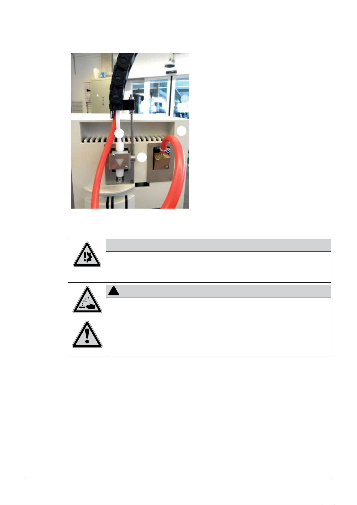
5.3.2 Connecting the transfer hoses of the K-377
On the K-377
• Connect the transfer hose and the steam hose
to the two fittings on top of the sealing cap
on the sampler arm. Secure both connections
with hose clamps 1.
The red steam hose has to be fixed to the first
position (marked with a red ring) – pointing to
the front of the instrument!
• Fix the plastic cable channel with the two provided screws 2 on the sampler arm.
48
K-375/376/377 Operation Manual, Version B
Page 49
5 Putting into operation
On the K-375
• Remove the tightening screw from the holder
on the valve 1.
(The screw is not required for connection to
K-377)
• Slide the ring of the chain fastener onto the
holder on the valve 1 and fix it by tightening
the threaded bar.
• Slide the the plastic holder of the transfer
connection onto the threaded bar 2. Hold it in
place by screwing the second nut hand-tight
on top.
• Mount the white transfer hose on the valve
using the provided screw connection 3.
• Mount the red steam hose on the steam valve
and secure it with a hose clamp 4.
5.4 Reagent/water and waste connections
Risk of device damage by exceeding the maximum permissible pressure for the cooling water inlet.
• Make sure never to exceed the maximum permissible pressure of 6 bar for the cooling water
Serious chemical burns by corrosives.
• Make sure that the tanks are connected correctly. If the wrong tank (e. g. reagent tank
NOTICE
inlet.
!
WARNING
containing NaOH) is connected to the pump labelled as „H
H2O is expected.
2O”, NaOH might be dosed while
49
K-375/376/377 Operation Manual, Version B
Page 50
5 Putting into operation
a H2O pump (for steam generator and sample
tube)
b Boric acid (H3BO3) pump
c NaOH pump
Fig. 5.5: Reagent, water and waste connections
NOTE:
All pumps are self-priming, no overpressure is necessary at the tanks!
If the sample tube waste and the receiver waste shall be collected in the same tank, the Y-piece
(contained in the standard delivery) can be used to merge both tubes.
Cooling water connection
Screw the cooling water hose to the cooling water inlet on the device side and connect it to the
water supply. The water pressure should not exceed 4 bar and the cooling water temperature should
not exceed 25 °C. The flanged screw coupling for the water connection has a standard screw thread
3
of G
/4“.
Drain cooling water
Place the drain hose for the cooling water directly into the drain (sink). For this purpose, shorten the
silicone hose to the optimal length.
Make sure that the drain hose has no kinks and sharp bends.
Secure the drain hose to avoid any flooding inside or in the vicinity of the instrument.
d Waste outlet (receiver waste)
e Waste outlet (sample tube waste)
f Cooling water outlet
g Cooling water inlet
Waste/aspiration hoses
The sample residue can be aspirated and collected separately from the receiver waste. For this
purpose a separate collection tank is necessary. The collection tank must be located lower than the
device to guarantee proper drainage.
Connect the waste hose to the waste outlet and place it directly into the collection tank. For this
purpose, shorten the EPDM hose to the optimal length. In order to prevent any back-flow, the hose
may be placed maximum 10 cm into the tank.
50
K-375/376/377 Operation Manual, Version B
Page 51
!
Risks and hazards for humans, animals and the environment.
• Make sure to carefully collect any residues that may be hazardous to humans, animals or the
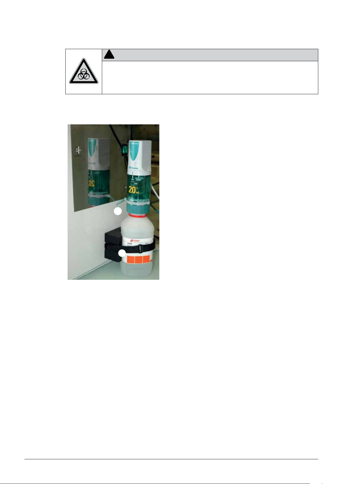
5.5 Buret unit for titrant
5 Putting into operation
WARNING
environment and to dispose them according to your local laws and regulations.
Fig. 5.6: Buret mounted on the titration solution
bottle
The bottle containing the titration solution can be fixed on the right side of the device using the
provided hook-and-loop fastener a. The buret (consisting of the dosing unit and the corresponding
drive unit) is mounted on the bottle. The preinstalled tube for the titrant b is guided through a cut-out
in the housing and can be connected to the dosing unit.
The tube of an additional buret for back titration can also be guided through the provided cut-out in
the housing.
NOTE
In case the buret gets blocked, refer to chapter 7.7.6 “Troubleshooting the dosing unit”. The
assembly of the dosing unit is explained in detail in the separate operating instructions delivered
together with the dosing unit.
51
K-375/376/377 Operation Manual, Version B
Page 52

5.6 Storage tank connection
To connect the storage tanks, proceed as follows:
• Cut the solaflex tube into pieces to the appropriate length.
• Insert a PTFE suction tube into the solaflex tube.
• Push a EPDM sealing ring over the solaflex tube.
• Now fasten the tubes to the tank with the red screw cover.
The storage tanks should not be positioned higher than the device itself and not lower than
1 meter below the instrument.
5 Putting into operation
Fig. 5.7: Tank connection
All pumps are self-priming, no overpressure is necessary at the tanks.
Risk of device damage by calciferous water or wrong rong connected tanks.
• Use only distilled water for the H2O storage tank to keep the steam generator maintenance-
• Make sure that the tanks are connected correctly. If the wrong tank (e. g. reagent tank
NOTICE
free.
containing NaOH) is connected to the pump labelled as „H2O“, the steam generator will get
damaged.
52
K-375/376/377 Operation Manual, Version B
Page 53

5.7 Level sensors
Four level sensors are contained in the standard delivery of the instrument. Three are intended for
the storage tanks (NaOH, H3BO3 and water) and one for the waste collection tank (either the sample
tube or receiver waste). Additional level sensors are available as optional equipment. Each individual
sensor is connected to the corresponding socket on the rear side of the device (see section 5.2.1).
The sensitivity of the capacitive level sensors can be adjusted to safely detect the liquid level, if
necessary.
Assemble the level sensors according to the following picture:
5 Putting into operation
Fig. 5.8: Assembly of the level sensors
• Mount the sensor at the tank using the provided O-ring (see a in figure 5.9) and connect it at
the rear-side of the device to the corresponding port (NaOH, H2O, H3BO3, Waste Sample Tube,
Waste Receiver, or Titrant). The sensitive side of the sensor (marked with the crosshair)
has to face the tank!
• Make sure the tank is filled with the corresponding liquid.
• Shift the sensor together with the rubber strap until it is located below the liquid level.
The red LED at the sensor should now be off.
• If the sensor does not safely detect the liquid:
Use a small screwdriver to set the sensitivity (with the small adjustment screw) of the sensor (see
b in figure 5.9).
53
K-375/376/377 Operation Manual, Version B
Page 54
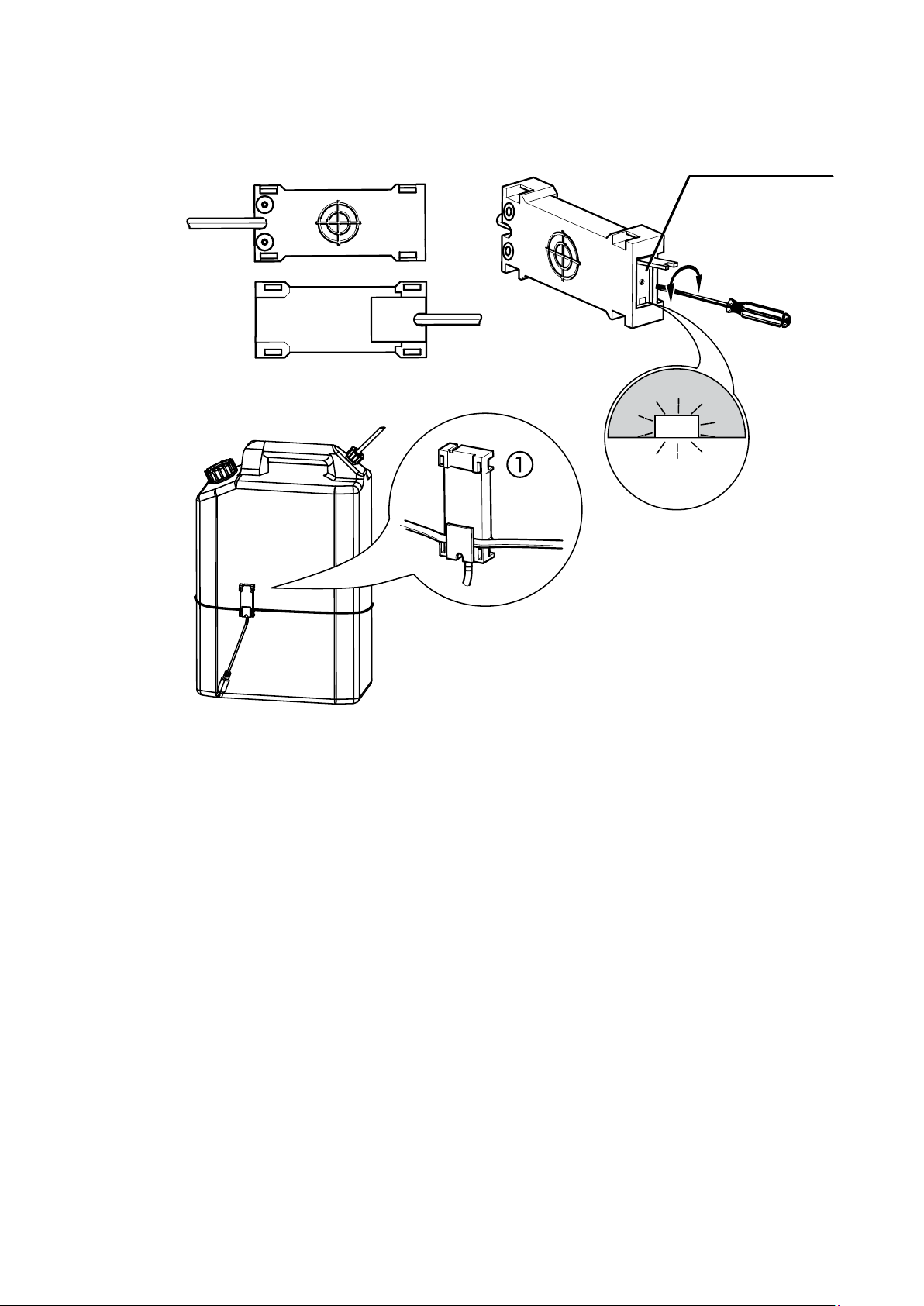
5 Putting into operation
Rear view: The crosshair marks the sensitive area
Front view:
b
Status LED
Adjustment screw
Fig. 5.9: Fixing the level sensors
NOTE
The sensor detects a liquid when the red LED is off.
The level sensor for the waste tank must be set active within the Settings Peripherals screen (See
chapter “6.9.1 Settings“). This is not necessary for the other sensors.
54
K-375/376/377 Operation Manual, Version B
Page 55

5.8 Connections to peripheral devices
The following devices and accessories can be connected to the K-375:
• up to 6 level sensors for monitoring the liquid level in storage or waste tanks
• a printer (via USB port) for printing e.g. results or methods
• a network cable (LAN) for storing data on a network place
• a sampler K-376/K-377 for automatic determinations of sample sequences
• a balance for the automatic acquisition of the sample weight
• a bar code reader for capturing sample data like IDs or batch numbers
• an additional external dosing unit for back titration
5.8.1 Connecting a printer
The K-375 supports printers with USB port and language PCL 3 or higher (PCL 5e, PCL 6, PCL 7
etc. e.g. from Hewlett Packard).
The printer is connected to the USB port marked with “Printer” (position e in Fig. 5.1).
NOTE
For using the printer make sure to switch on the printer first, followed by the K-375.
5 Putting into operation
5.8.2 Connecting a network cable
Instead of storing data locally on the instrument, it can also be stored on a network place. A network
cable can be connected to the device on the LAN port on the rear side. For adapting the network
settings refer to chapter “6.9.1 Settings Network”.
More details regarding the network connection can be found in the document “Manual – Network
connection K-375”, which can be obtained from any authorized BUCHI representative.
5.8.3 Connecting a KjelSampler K-376 or K-377
Connect the KjelSampler K-376 or K-377 to the KjelMaster K-375 by means of the supplied RS232
cable.
5.8.4 Connecting a balance
The connected balance must fulfill the following criteria:
• The balance must be equipped with an RS232 interface and a „print“-button. Otherwise it is not
possible to send sample weights to the K-375.
• The RS232 settings of the balance and the K-375 software must correspond.
• The sent command from the balance must have the following string: floating point_unit.
The weight is transferred to and stored in the K-375. Negative values are automatically converted into
positive sample weights.
For the configuration of the balance refer to Settings Peripherals screen (See chapter “6.9.1
Settings“).
55
K-375/376/377 Operation Manual, Version B
Page 56
5.8.5 Connecting a bar code reader
A USB barcode reader can be used to read in data, e.g. a sample name or the weight of a sample,
that is printed in form of a barcode. The barcode reader can be connected to the corresponding USB
connector on the rear side of the K-375. (See chapter 5.2.1 “Connections of the K-375”.)
5.8.6 External dosing unit for back titration
The external dosing unit is connected to the port “Base” on the rear side of the instrument. (See
position j in figure 5.1) . For installation and assembly of the dosing unit, refer to the instruction
manual of the dosing unit.
NOTE
For optimum performance and minimal fluctuation of the measured values, the dosing tip of the
dosing unit with the titrant always has to be placed in position “TITR” of the receiver. The second
dosing tip can be placed in any other position!
5.8.7 Electrode connection
Connect the pH electrode to the electrode cable already mounted. Remove the pH electrode from
the storage cap and insert it into the titration vessel.
5 Putting into operation
Risk of device damage wrong storage.
• Always store the pH electrode in the storage cap in saturated KCl solution (4.2 mol/L).
NOTICE
A pH electrode should not be stored dry as this would destroy the diaphragm. If a pH electrode has been stored dry, let it regenerate in saturated KCl for 24 hours or at least over night
prior to further use.
56
K-375/376/377 Operation Manual, Version B
Page 57

5.9 Preparing the system
5.9.1 Preparing the software
In general it is recommended to check and adapt all device settings, located under
HOME Settings
previous to the first use of the instrument.
Following a selection of the most common settings to be adapted is provided:
Define regional settings
HOME Settings Regional settings
Choose device language, keyboard layout, and date and time format
Set date and time
HOME Settings Date and time
Set date, time, and time zone
5 Putting into operation
Define user (optional)
HOME Settings User administration
Different users with specific user rights can be defined. As long as no user is defined, no user administration will be used. For more details refer to the section “6.3 User concept”.
Check peripherals
HOME Settings Peripherals
Make sure all connected peripherals are selected and configured.
Specify an import and export path for results and other data
HOME Settings Import and Export
Data can be exported either to a USB device or to a network data share. If a network data share
shall be used, a path needs to be specified.
Depending on your preferred applications and methods the following items have to be defined:
Volumetric solutions
HOME Volumetric Solutions
Define all solutions that may be used for your applications.
Reference substances (optional)
HOME Reference Substances
Specify the reference substances together with their theoretical values.
Method (optional)
HOME Methods
Define a new determination method or modify an existing method if necessary.
Blank Corrections
HOME Blank Correction
Determine the general behavior of the system with respect to the blank correction.
57
K-375/376/377 Operation Manual, Version B
Page 58

5.9.2 Preparing the hardware
There are only a few tasks that have to be performed in order to prepare the hardware for the first
use:
5 Putting into operation
Calibrate the pumps for H
2O, H3BO3 and NaOH
HOME System Preparation Pump calibration
• Select the pump to be calibrated (H
2O, NaOH or H3BO3).
• Enter the target “Dose volume”, e.g. 50 mL.
• Press START to start the calibration procedure.
• Measure the actually dosed volume and enter it as calibration volume in the displayed screen.
Repeat the calibration procedure, until the measured and the dosed volume correspond.
• An acceptable difference at 50 mL is ±5 mL.
NOTE
2O and NaOH can be dosed into the sample tube and then poured for measurement into a gradu-
H
ated cylinder.
The H3BO3 can be dosed directly into the receiving vessel and then poured into a graduated cylinder.
Rinsing of the buret and the titration hoses
HOME System Preparation Buret functions Dose
Dose some liquid to a waste vessel to rinse the buret and the titration hoses. Repeat the rinsing, until
the whole buret and all the titration hoses are filled with titration solution. Make sure there are no air
bubbles in the buret or in the titration hoses.
Calibration of pH electrode
HOME System Preparation Calibration pH electrode
Calibrate the pH electrode by following the instructions on the screen (see chapter 6.6.1).
NOTE
We recommend to calibrate the pH electrode regularly (e.g. every morning) with buffer solution
pH 7 and pH 4.
58
K-375/376/377 Operation Manual, Version B
Page 59

6 Operation
This chapter gives examples of typical device applications and instructions on how to operate the
device properly and safely.
!
CAUTION
Risk of injury.
• Never operate the device with damaged glassware.
6.1 The operating principle
The graphical user interface of the K-375 is operated via the touch screen. To select a button or
an input element in the dialog window, you simply touch the screen using a soft blunt object or a
fingertip.
6 Operation
6.2 The home screen
The central element of the user interface is the home screen:
!
CAUTION
Risk of injury.
• Never touch the surface of the touchscreen with pointed or sharp objects! Otherwise the
screen might get damaged and splinter.
Fig. 6.1: The home screen
The home screen contains 4 different areas with buttons leading to the corresponding dialog
windows:
59
K-375/376/377 Operation Manual, Version B
Page 60

Functional area Icon Dialog window Description
Determination
All tasks related
to the sample
measurement
itself (System
preparation and
sample definition)
System Preparation and
manual operation
Perform all tasks related to the preparation of the system,
like Preheating, Priming, Cleaning, Aspiration, periodic
tasks like electrode calibration or manual tasks related to
burets, pumps, and a sampler.
Single Sample Determine a single sample based on Type, Name,
Method,and (Result-)Group. (Plus additional parameters
depending on the sample type.)
Sample Lists Create a sample list – a list of samples to be determined one
by one without an auto sampler.
Sequences Create a sample sequence with predefined samples per rack
to be processed using an auto sampler. (Only visible if an
auto sampler has been configured under “Settings”.)
Results
Result Groups Create and view groups for the storage of your results.
All tasks related
to the results
of the system
Last Results View, print or export the results of the last sample determi-
nations.
(storage,
viewing, printing
and selection)
Blank Correction Calculate mean blanks, enter manual blanks or adapt the
settings for the correction of blanks.
6 Operation
Determination
Parameters
All tasks related
Methods Create, import, edit, and manage your determination
methods.
Volumetric Solutions Manage all used volumetric solutions.
to the methods
and the used
solutions and
Reference Substances Manage all used reference substances.
substances.
Device
All tasks related
to the device
itself. (Settings,
Settings Adapt all device settings, like date and time, network
settings, peripherals, and user management.
Utilities Set your backup path for the database backup, use the lab
timer or switch to the demo mode of the instrument.
Utilities and
Diagnostics)
Diagnostics Switch to service mode and view or check all relevant
system components.
Logout Login/Logout to the instrument. (Only visible if User manage-
ment is used.)
By pressing the HOME button on the bottom of each screen you can return to the home screen from
any other screen.
60
K-375/376/377 Operation Manual, Version B
Page 61

6.2.1 The title bar
The title bar is present on top of any screen and consists of the following components:
Fig. 6.2 Title bar
1 Icon of the current dialog
2 Title of the current dialog
3 System status icon
4 Options, hints or help for the current screen
5 Date & Time
6.2.2 The bottom bar
6 Operation
Like the title bar, the bottom bar is always present on any screen. It consists of 5 different buttons,
whose function will never change (there is one exception: the START button will be switched to a
PAUSE button during a running sequence):
Fig. 6.3 Bottom bar
1 HOME – this button will bring you back to the home screen from any other screen
2 SHOW/HIDE STATUS – shows or hides the Status view
3 READY/STANDBY – toggles the system mode between standby and ready. In standby mode
the steam generator is powered off for energy saving reasons.
4 START/PAUSE – starts a task, or pause a running sequence
5 STOP – stops a task.
This button also acts as an EMERGENCY STOP switch. If the device malfunctions or there is
an operating error, you can stop all current tasks by pressing the STOP button. (The current will
be switched off, resulting in the closure of all valves.)
61
K-375/376/377 Operation Manual, Version B
Page 62

6.2.3 System status icons
Icon Meaning
The device is ready without any restrictions.
A sample determination/task can be started.
A task is running (Determination, Preheating, Cleaning etc.)
A sample determination/task can’t be started.
A warning message is shown under Status/Info.
Check Status/Info before starting a task. Depending on the cause for the
warning, the start button may be inactive.
There are errors that have to be remedied before a determination can be
started (e.g. titrator not ready, dosing unit not connected etc.)
6 Operation
The device is in standby mode (steam generator switched off, power save
mode)
– Press READY to return to operating mode.
Serious error – contact BUCHI service.
Warnings and info messages can be viewed in the INFO section of the status view. (Accessible via
the button SHOW/HIDE STATUS in the bottom bar.)
62
K-375/376/377 Operation Manual, Version B
Page 63

6.3 User concept
The software recognizes two different kinds of users – the administrator, with unrestricted access to
any area and to any function of the system, and the operator, whose access is restricted to the tasks,
necessary for the routine operation of the instrument.
The operator is allowed to
• perform tasks for the system preparation and periodic tasks,
• set up and perform any kind of sample determinations,
• allocate results to result groups,
• view, filter and export results,
• calculate mean blanks,
• adapt the titer of the volumetric solutions,
• specify the protein factor for determinations.
The access to the device settings is also restricted to the definition of the result units and some other
settings (language, printer, sampler etc.)
6 Operation
NOTE
In case you forgot the password for your administrator account, you can ask your BUCHI service
center for a password for the BUCHI Administrator. The account of the BUCHI administrator will
always be present on your system and can not be deleted. The password will be valid for one day,
enabling the creation of a new administrator account on your system.
6.4 Editable and non-editable menu items
• All menu items with a white background can be viewed, but not edited.
• All menu items, displayed with a grey background can be edited or can be clicked to display
further information. A small arrow at the right end of the push button indicates existence of further
screens.
In the example below the Titer is the only attribute that may be changed by an operator:
63
K-375/376/377 Operation Manual, Version B
Page 64

Fig. 6.4 Volumetric solutions screen
6 Operation
If an item is editable or not, depends on the rights of the user. All resources that are present by
default (standard methods, volumetric solutions, and reference substances) can not be deleted –
those items are marked with the symbol of a small padlock.
NOTE
Sample lists and sequences can be locked and unlocked by users with administrator rights therefore
the check mark in front of the list or sequence has to be checked and the LOCK button has to be
pressed.
Fig. 6.5 Listed item
1 Check box for selecting an item
2 Padlock – indicates items that can not be deleted
3 Arrow symbol – indicates further screens belonging to the same item
NOTE
To select a larger number of sequenced items proceed as follows:
• check the check box of the first item
• check the check box of the last item by pressing and holding it, until all items in between become
automatically selected.
64
K-375/376/377 Operation Manual, Version B
Page 65
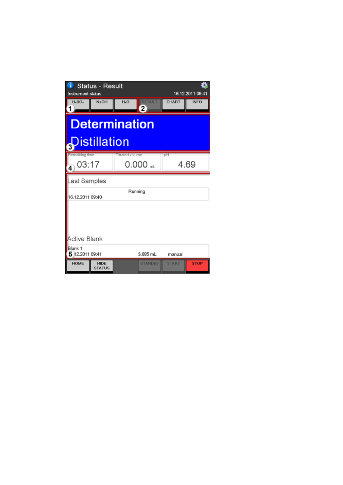
6.5 The status view
The status view of the system is accessible via the SHOW/HIDE STATUS button in the bottom bar:
6 Operation
Fig. 6.6 The status view
1 Buttons for direct dosing of boric acid, sodium hydroxide, and water.
NOTE
The dosed amount per click can be adapted by a user with administrator rights under
HOME SETTINGS Dosage volume in status view
2 Buttons for switching between RESULT-, CHART-, and INFO-display.
3 Status field – indicates the system status and shows the active step of the running task.
4 Progress indication for the running task (remaining time, titrated volume, and measured pH)
5 Information area – shows last results with the currently active blank, the determination chart or
system information.
65
K-375/376/377 Operation Manual, Version B
Page 66

Colors of the status field
Color of status field Meaning
Green – the system is ready for sample determinations.
Orange – the system is in standby mode. (The steam generator
Blue – the system is busy (preparative task, periodic task, or
Red – the system has an error, or a system component is not
6 Operation
is powered off.)
sample determination running).
ready.
66
K-375/376/377 Operation Manual, Version B
Page 67
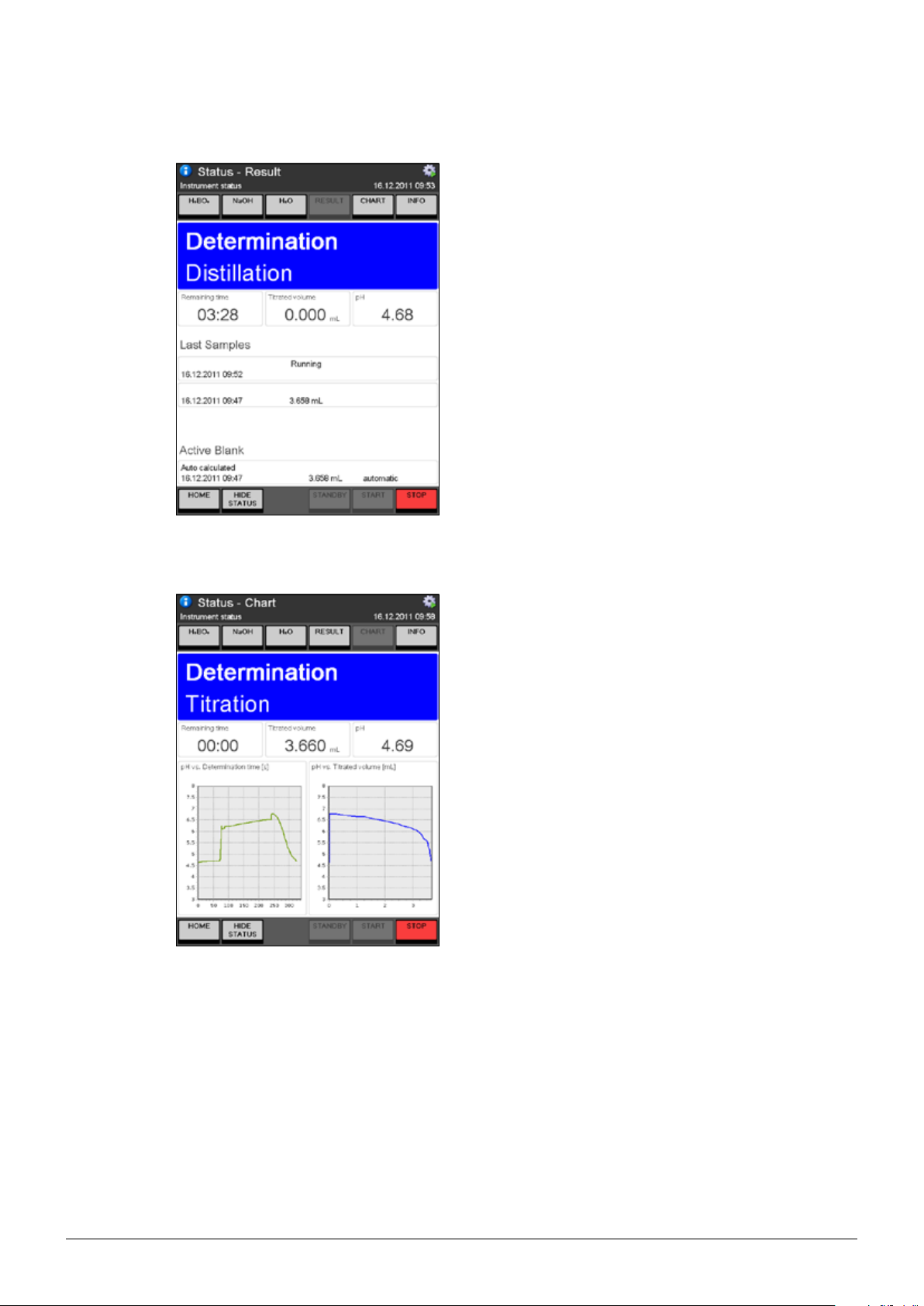
6.5.1 RESULT display
6 Operation
The RESULT display of the Status view shows
the last 3 results and the currently active blank
together with its type and value.
6.5.2 CHART display
The CHART display of the Status view shows two
charts:
• pH versus determination time [s] and
• pH versus titrated volume [mL]
NOTE
The charts are only temporarily available and will be
overwritten with the charts of the next performed
determination. They are excluded from the manual
data export. Each result that is exported automatically will always contain the charts.
67
K-375/376/377 Operation Manual, Version B
Page 68
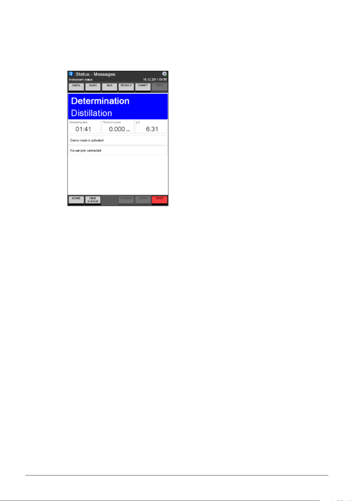
6.5.3 INFO display
6 Operation
The INFO display of the Status view shows all
system and error messages.
68
K-375/376/377 Operation Manual, Version B
Page 69
6.6 Determination
In general there are three different ways for a sample determination with the K-375:
• Determination of single samples (one by one without a sampler)
• Determination of a predefined sample list (one by one without a sampler)
• Determination of a complete rack in a predefined sequence (with a sampler K-376 or K-377)
Table 6-6: Sample determination possibilities
Recommended
for:
Operation
procedure:
6 Operation
Single sample determination Sample List determination Sequences (automatic rack determina-
tion with sampler)
• Only few samples
• Express sample
(e. g. interruption of a group)
• Method evaluation
• Many samples (> 10)
• Routine analysis
• Number of samples in a
list is variable
• Determination with
digestion
• Many samples (> 20)
• Routine analysis
• The maximum number of
samples in a rack is
defined ( 4 samples for the
express and 12 respectively
20 samples for the normal
racks)
1. Enter data for the first sample
2. Determine the first sample
3. Enter data for the second
sample
4. Determine the second
sample
1. Enter data for all samples
2. Determine the first
sample
3. Determine the second
sample
4. ...
1. Enter data for all samples
2. Determine the first sample
3. Determine the second
sample
4. ...
5. ...
Description: Without sampler. Without sampler. With KjelSampler K-376/K-377.
NOTE
Pressing the red STOP key on the touchscreen stops all processes immediately.
NOTE
Before starting a sample determination always check the system status icon in the upper right corner
of the display to ensure the device is ready for a determination without any restrictions.
The following icon should be displayed:
Other icons may indicate the necessity of preliminary user interaction to prepare the device or to
solve problems. For details refer to section ”6.2.3 System status icons”.
69
K-375/376/377 Operation Manual, Version B
Page 70
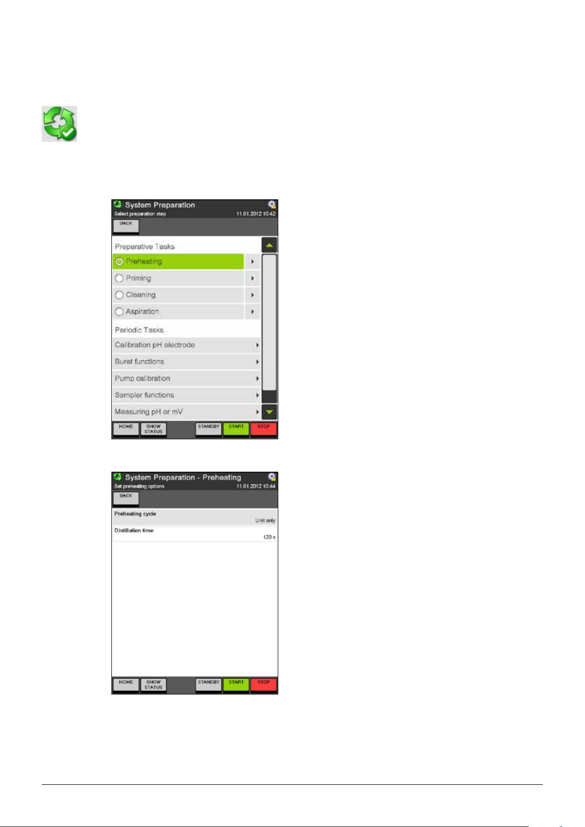
6.6.1 System Preparation
Within the area System Preparation all tasks related to the preparation of the system, like Preheating,
Priming, Cleaning, and Aspiration can be defined and performed. In addition periodic tasks like electrode or pump calibration and certain manual tasks related to burets, a sampler, or pH measurement
can be performed.
Preparative Tasks
6 Operation
The System Preparation dialog is subdivided in two
sections:
Preparative Tasks
• Preheating
• Priming
• Cleaning
• Aspiration
(screenshot stretched)
Periodic Tasks
• Calibration pH Electrode
• Buret functions
• Pump Calibration
• Sampler functions
• Measuring pH or mV
Preheating
The glass parts of the distillation system have to
be preheated prior to analysis. This is done by
means of a clean and empty sample tube. It is
recommended to perform a preheating, when the
glassware has cooled down. A status message on
the status view will inform the user if preheating is
required.
If an auto sampler is configured under “Settings”,
select either “Unit only” or “Via Sampler” for
“Preheating cycle”.
70
For “Unit only” only the glassware and tubing of the
K-375 device is heated up. With the option “Via
Sampler” also glassware and tubing of a connected
sampler can be included for the heat-up procedure.
The duration of the preheating procedure (“Distillation
time”) can not be changed.
Press START to start the preheating procedure.
K-375/376/377 Operation Manual, Version B
Page 71
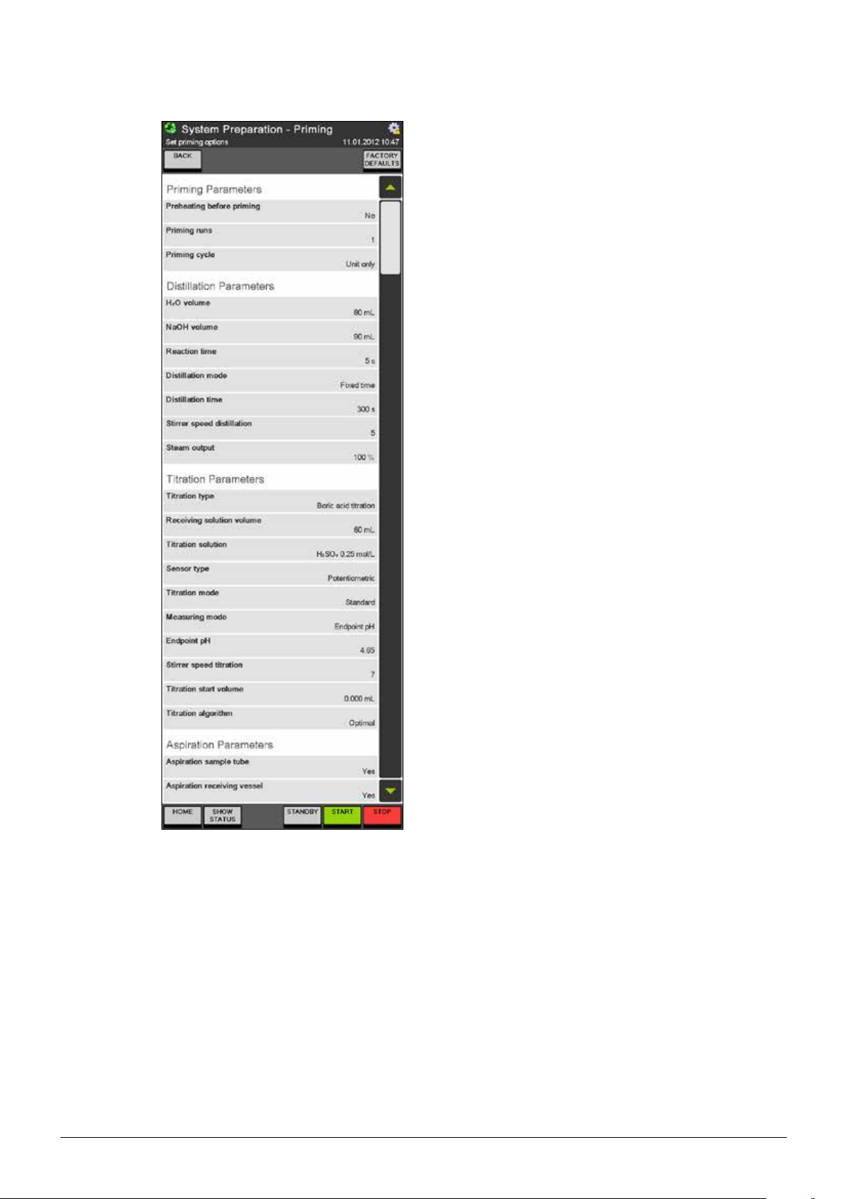
6 Operation
Priming
Priming is used to prepare the entire system. This
preparation procedure includes the distillation and
titration with a clean and empty sample tube, as
well as the dosing of chemicals. It is recommended
to perform a priming at least once a day, before
starting analysis. The priming procedure is similar to
a sample determination method and can be modified.
Priming Parameters
Select Yes for “Preheating before priming” if prior to
the priming procedure a preheating procedure shall
be performed.
Set the number of “Priming runs”.
Set “Priming cycle” to “Via sampler”, if the priming
procedure should be performed via a present
sampler. (Only visible if a sampler has been configured under “Settings”.)
(screenshot stretched)
The other parameter sets Distillation Parameters,
Titration Parameters, and Aspiration Parameters are just the same like within a method. A
detailed explanation can be found in the section
“6.8.1 Method”.
Press START to start the priming procedure.
Press FACTORY DEFAULTS to reset the settings
of this screen.
NOTE
If only one priming cycle is selected and no aspiration, no aspiration will be done at all.
If more than one priming cycle is selected and no
aspiration, the sample tube and the receiving vessel
will be aspirated between the single priming cycles,
but not after the last cycle has been performed –
instead the system will be stopped after the last
run.
71
K-375/376/377 Operation Manual, Version B
Page 72
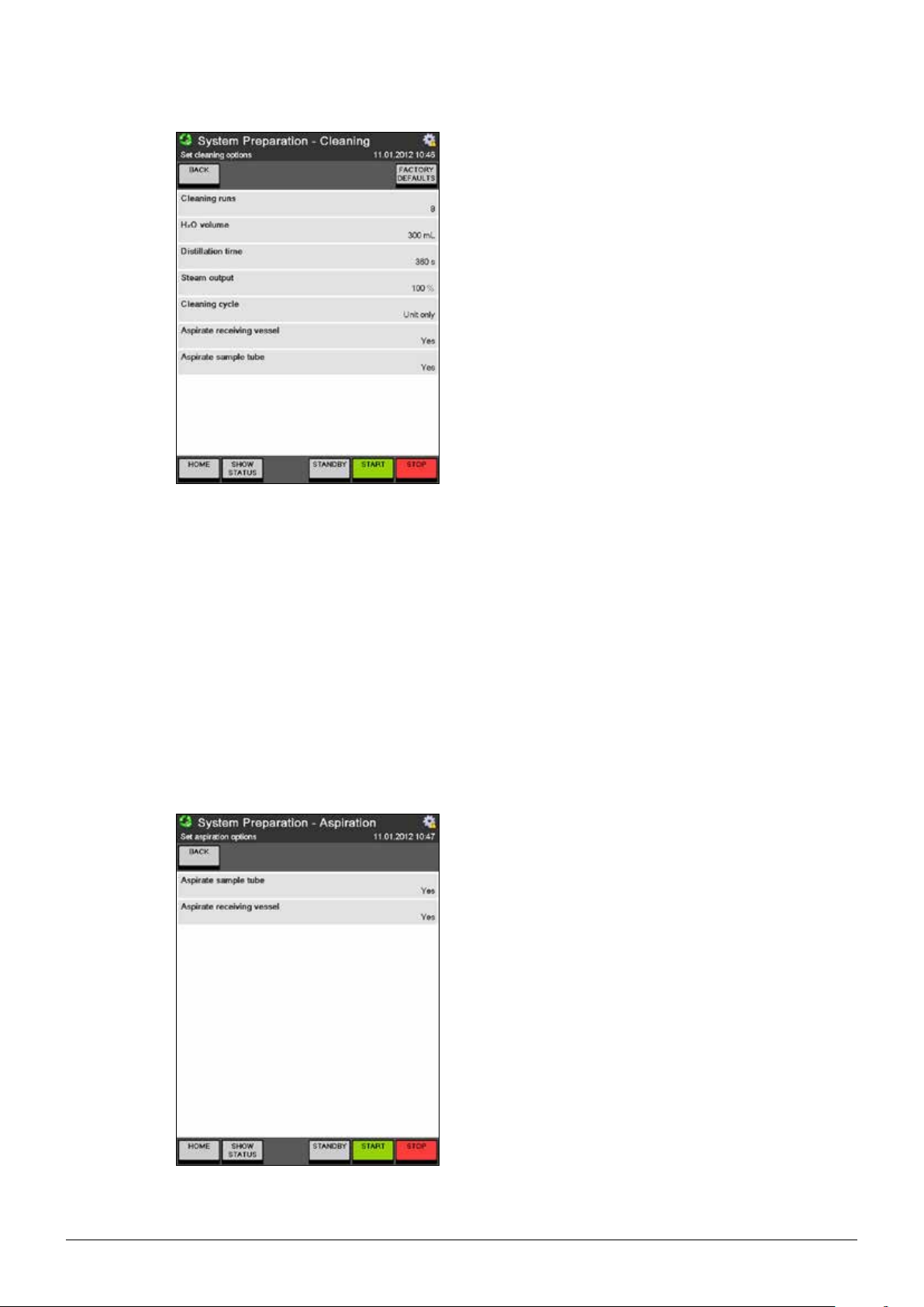
6 Operation
Cleaning
With regular cleaning, the lifetime of the glass
parts can be extended. Thus it is recommended to
perform a few cleaning runs before switching off the
unit. The cleaning procedure is performed by means
of a distillation with water in a clean sample tube.
Thus all residues from the last sample determination
can be removed.
The volume of water to be used for each cleaning
cycle and the number of cleaning cycles can be
adapted just like the distillation time in seconds.
The steam output can be set between 30 and
100 %. In case a sampler is present, the Cleaning
cycle can be enhanced from “Unit only” to “via
sampler” – in this case the hoses from and to the
sampler are also cleaned.
Press START to start the cleaning procedure.
Press FACTORY DEFAULTS to reset the settings
of this screen.
NOTE
If only one cleaning run is selected and no aspiration, no aspiration will be done at all.
If more than one cleaning run is selected and no
aspiration, the sample tube and the receiving vessel
will be aspirated between the single cleaning runs,
but not after the last run has been performed –
instead the system will be stopped after the last
sample.
Aspiration
The aspiration procedure automatically aspirates the
sample tube and/or the receiving vessel. All waste
liquids of both sources can be collected separately.
Select “Yes” to enable automatic aspiration or “No”
to switch of automatic aspiration for the respective
vessel.
72
Press START to perform the aspiration.
K-375/376/377 Operation Manual, Version B
Page 73
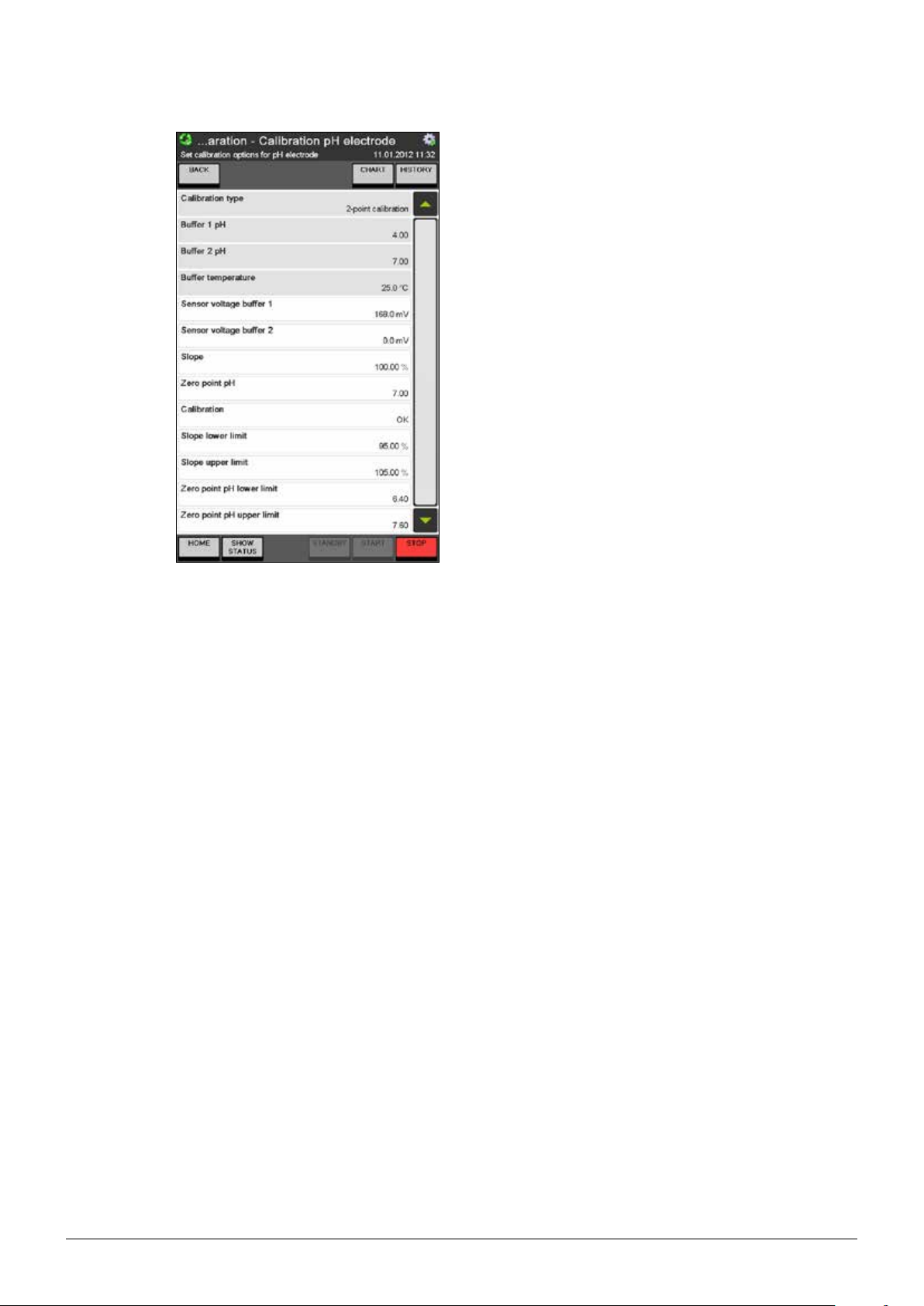
(screenshot stretched)
6 Operation
Calibration pH electrode
It is recommended to calibrate the electrode
every day before starting sample determinations.
The electrode should be treated according to the
recommendation described in the electrode supplementary sheet.
We recommend replacing the electrode, if it
does not fulfill the following criteria at 25 °C room
temperature anymore:
Slope 95 – 105 %
Zero point pH 6.4 – 7.6
(For pH electrodes other than the ones supplied by
BUCHI, additional criteria might be important.)
NOTE
It is recommended to use buffer solutions pH 4.00
and 7.00. (For a 3 point calibration in addition the
buffer solution for pH 9.21 is recommended.)
Discard buffer solutions after usage. Work with
fresh solutions every day.
Select either a 2 point or a 3 point calibration.
Prepare and specify the buffer solutions and the
temperature of the buffer solutions.
Press START to start the calibration and follow the
instructions on the screen.
Press CHART to switch to the chart-display of the
last calibrations or press HISTORY to view the data
of the last calibrations.
NOTE
A pH electrode should never be stored dry.
If it has been stored dry, regenerate the electrode
in saturated KCl for 24 hours or at least over night
prior to further use. Do not touch the tip of the electrode and do not wipe it with tissue paper or cloth.
73
K-375/376/377 Operation Manual, Version B
Page 74

6 Operation
pH calibration history chart
The charts for the pH calibration are accessible
via the calibration dialog for the pH electrode by
pressing the CHART button.
The two charts show the alteration of slope and
zero-point of the pH electrode over the range of the
last ten calibrations. Thus a change of the performance of the electrode can be detected at first
glance.
The chart can be printed with PRINT.
pH calibration history
The pH calibration history is accessible via the calibration dialog for the pH electrode by pressing the
HISTORY button.
A list, showing slope, zero point, time & date, and
if the calibration was ok or not is displayed. By
clicking on a single row, the detailed calibration data
for the corresponding calibration can be viewed.
The history can be printed with PRINT.
With DELETE the complete history (except of the
data of the latest calibration) can be deleted.
Buret functions
Select the buret function to be performed:
• Prepare,
• Discharge, or
• Dose
74
Press START to start the selected buret function.
NOTE
If more than one buret is connected to the instrument, the respective buret unit (Acid or Base) can
also be selected. An additional buret for a base can
be connected to the device (e.g. for back titrations)
and will be detected automatically during power-on
of the instrument.
K-375/376/377 Operation Manual, Version B
Page 75

Pump calibration
6 Operation
Select the pump to be calibrated (H
2O, NaOH or
H3BO3).
Enter the target “Dose volume”, e.g. 50 mL.
Press START to start the calibration procedure.
Measure the actually dosed volume and enter it as
calibration volume in the displayed screen. Repeat
the calibration procedure, until the measured and
the dosed volume correspond.
An acceptable difference at 50 mL is ±5 mL.
NOTE
2O and NaOH can be dosed into the sample
H
tube and then poured into a graduated cylinder for
measurement.
The H3BO3 can be dosed directly into the receiving
vessel and then poured into a graduated cylinder.
Sampler functions
The actions “Move to zero position” and “Move to
service position” are available for both sampler types
(1-tray and 2-tray). For a 2-tray sampler the arm is
moved to the corresponding zero or service position
of the tray, the arm is actually positioned in.
For a 2-tray sampler it is also possible to move the
arm of the sampler with “Move to tray A” from tray B
to the zero position of tray A and vice versa.
Press START to move the arm to the selected posi-
tion.
75
K-375/376/377 Operation Manual, Version B
Page 76

6 Operation
Measuring pH or mV
Using this functionality a direct measurement can
be performed with the potentiometric or colorimetric
sensor.
Select either potentiometric or colorimetric for the
“Sensor type”. Adapt the stirrer speed during the
measurement to your needs.
Press START to start the measurement.
76
K-375/376/377 Operation Manual, Version B
Page 77

6.6.2 Single Sample
In general four different kinds of samples can be determined:
• Blanks (can be used for the correction of sample results).
• Samples
• Reference substances (results can be rejected if a reference substance is outside of its
predefined limits)
• Control blanks (to be determined for information only – can not be used for any sample correc-
tions)
The single sample determination is thought for a small amount of samples to be measured without a
sampler present.
6 Operation
First of all the sample type has to be selected:
• Blank,
• Sample,
• Reference substance or
• Control blank.
According to the selected type of sample,
different parameters are available:
For samples of type Blank,
press “Name” and enter a name for the blank
result.
Press “Method” and select the method to be
used for the determination of the blank from the
list of the available methods.
Press “Group” and select a result group for the
storage of the result from the list of the available
result groups. (It is also possible to create a new
result group using the New Group button.)
77
K-375/376/377 Operation Manual, Version B
Page 78

6 Operation
For samples of type Sample,
press “Name” and enter a name for the sample
result.
Press “Sample weight” and enter the weight of the
sample in [g] or [mL].
Press “Protein factor” and enter the protein factor
for the determination of the results.
Press “Method” and select the method to be used
for the sample determination from the list of the
available methods.
Press “Group” and select a result group for the
storage of the result from the list of the available
result groups. (It is also possible to create a new
result group using the New Group button.)
For samples of type Reference Substance,
press “Name” and enter a name for the result of the
reference substance determination.
Press “Reference substance” and select the reference substance from the list.
Press “Sample weight” and enter the weight of the
sample in [g] or [mL].
Press “Method” and select the method to be used
for the determination of the reference substance
from the list of the available methods.
Press “Group” and select a result group for the
storage of the result from the list of the available
result groups. (It is also possible to create a new
result group using the New Group button.)
For samples of type Control Blank,
press “Name” and enter a name for the control
blank result.
Press “Method” and select the method to be used
for the determination of the control blank from the
list of the available methods.
78
Press “Group” and select a result group for the
storage of the result from the list of the available
result groups. (It is also possible to create a new
result group using the New Group button.)
K-375/376/377 Operation Manual, Version B
Page 79

6.6.3 Sample Lists
With the sample list functionality it is possible to predefine a complete list of samples to be determined one by one without a sampler. Each sample list can be filled with any number of predefined
samples. If all samples of a sample list are selected at once for the determination, they will be determined in the same order they were added to the list. It is also possible to determine the samples in a
different order by selecting individual samples from the list.
The type (Blank, Sample, Reference substance or Control blank), and name of each sample can
be chosen freely. The same applies for the used method and the result group for the storage of the
result.
For samples in addition the weight and the protein factor have to be specified. If a compatible
balance is connected to the instrument, the weight of each sample can be automatically taken over
from this balance.
NOTE
For each new sample the entries of the previously entered item are used as default values (the default
value for the name depends on the type of the sample – in this case the name of the last sample of
the same type is taken as default). All default values can be overwritten.
6 Operation
To start a sample list determination you have to enter the list and to select the samples to be determined. To select a complete list simply check the check box in front of the first sample and check
and hold the check mark in front of the last sample in the list or use SELECT ALL. As a result all
samples in between will also be checked. (This will also work for deselecting a larger number of
samples.) To exclude samples from the determination uncheck the check mark in front of the sample
in question.
Once a sample has been determined (with or without a valid result) it is deleted from the list and the
next sample in the list becomes sample number one (the next sample to be determined). After all
samples of a list have been processed, the empty list remains on the device (it can either be refilled
with samples for the next determinations or deleted manually).
The Sample Lists screen shows a list of all
present Sample Lists.
New Sample Lists can be created with NEW and
existing ones can be deleted, renamed or copied.
It is also possible to import sample lists that have
been set up on a personal computer from a USB
device or a network place.
User with administrator rights can also lock and
unlock sample lists.
79
NOTE
Locked sample lists can not be edited and the
contained samples can not be determined but
they can be used as template by copying them.
K-375/376/377 Operation Manual, Version B
Page 80
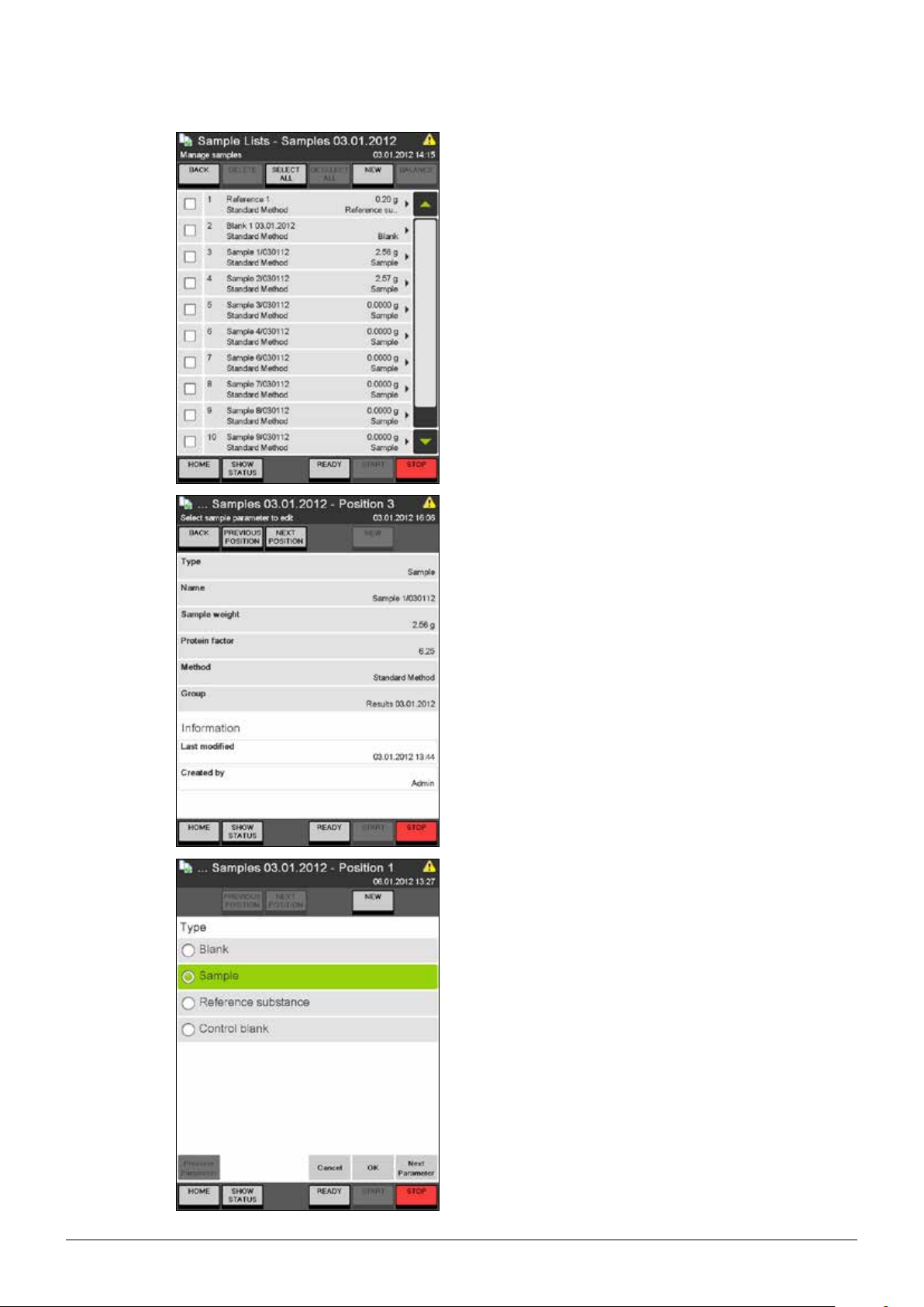
6 Operation
Within each sample list all contained samples
are listed together with name, type, method
and weight (except blanks, where no weight is
needed).
Samples are added to the list with the NEW
button. Already existing samples can be deleted
after being selected.
With the SELECT/DESELECT ALL buttons all
samples can be selected/deselected at once.
When adding a new sample, always a sample of
the same type like the previously added sample is
added automatically. All parameters of the newly
added sample can be adapted. Using the buttons
PREVIOUS/NEXT POSITION it is possible to
navigate from one set of sample parameters
to the parameters of the previous or following
sample in the list.
80
The first parameter for each sample is the sample
type:
• Blank,
• Sample,
• Reference substance or
• Control blank.
Press NEW to enter a sample of the selected
type on the next position without leaving the
screen.
With OK the sample is added to the actual position and the sample list is displayed again.
According to the selected type of sample, a
different set of parameters is offered.
K-375/376/377 Operation Manual, Version B
Page 81
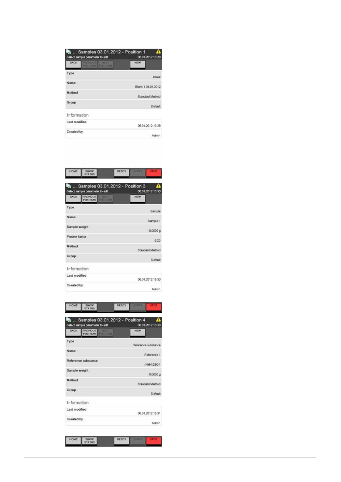
6 Operation
For samples of type Blank,
press “Name” and enter a name for the blank
result.
Press “Method” and select the method to be
used for the determination of the blank from the
list of the available methods.
Press “Group” and select a result group for the
storage of the result from the list of the available
result groups. (It is also possible to create a new
result group using the New Group button.)
For samples of type Sample,
press “Name” and enter a name for the sample
result.
Press “Sample weight” and enter the weight of
the sample in [g] or [mL].
Press “Protein factor” and enter the protein factor
for the determination of the results.
Press “Method” and select the method to be
used for the sample determination from the list of
the available methods.
Press “Group” and select a result group for the
storage of the result from the list of the available
result groups. (It is also possible to create a new
result group using the New Group button.)
For samples of type Reference Substance,
press “Name” and enter a name for the result of
the reference substance determination.
Press “Reference substance” and select the reference substance from the list.
81
Press “Sample weight” and enter the weight of
the sample in [g] or [mL].
Press “Method” and select the method to be
used for the determination of the reference
substance from the list of the available methods.
Press “Group” and select a result group for the
storage of the result from the list of the available
result groups. (It is also possible to create a new
result group using the New Group button.)
K-375/376/377 Operation Manual, Version B
Page 82
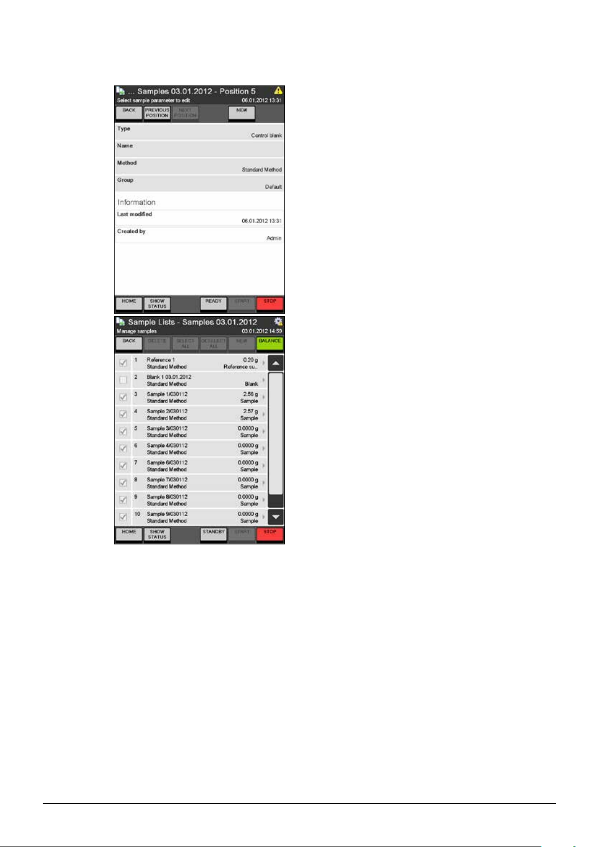
6 Operation
For samples of type Control Blank,
press “Name” and enter a name for the control
blank result.
Press “Method” and select the method to be
used for the determination of the control blank
from the list of the available methods.
Press “Group” and select a result group for the
storage of the result from the list of the available
result groups. (It is also possible to create a new
result group using the New Group button.)
Using the BALANCE button the weight of samples
can be taken over from a connected balance:
• Select all samples using the SELECT ALL
button
• Press BALANCE – all blanks and control
blanks are automatically deselected (no
weight is needed for blanks)
• Place the first sample on the balance and
press Enter on the balance – the first weight
is taken over from the balance and entered
into the first checked sample in the list.
• Proceed with the next sample
• When all sample weights have been taken
over, the balance mode is automatically left.
NOTE
Using a bar code reader it is also possible to
read in every sample related data like name or
weight from a barcode. The read in data is automatically filled in the active input field.
82
K-375/376/377 Operation Manual, Version B
Page 83

6.6.4 Sequences
The Sequences button is only available if an auto sampler is present and configured under
Device Settings Peripherals Sampler present
If the sampler has been installed and prepared properly, a sample series to be determined with a
one- or two-tray sampler can be defined and pre programmed via a sequence.
A sequence contains a number of steps defining the samples itself and the necessary system tasks
like preheating, priming, aspiration etc.
The following types of steps may be used within a sequence:
Step Explanation
Preheating The preheating procedure is performed according to the settings under
Priming The priming procedure is performed according to the settings under
Rack 4 Enter the sample details for a four-place express rack. For a 2-tray sampler the tray position (A or
Rack 12 Enter the samples for a 12 place rack. For a 2-tray sampler the tray position (A or B) can be
Rack 20 Enter the samples for a 20 place rack. For a 2-tray sampler the tray position (A or B) can be
Pause The sequence is stopped until it is continued by pressing Start.
Cleaning The cleaning procedure is performed according to the settings under
Aspiration The aspiration procedure for the sample tube and the receiving vessel is always performed, unless
Dose H
Standby The device is sent to Standby mode.
6 Operation
System Preparation Preheating
System Preparation Priming
B) can be selected using the SETTINGS button within the step.
This step can be edited within the sequence.
selected using the SETTINGS button within the step.
This step can be edited within the sequence.
selected using the SETTINGS button within the step.
This step can be edited within the sequence.
This step cannot be changed.
System Preparation Cleaning
the aspiration parameters of the referenced method are set to No. (In this case the sample determination will stop after the determination of the sample with the corresponding method.)
3BO3 This step is thought for the protection of the electrode. 50 mL of boric acid are dosed to the
receiving vessel to keep the electrode immersed during non-usage of the instrument.
This step cannot be changed.
This step cannot be changed.
NOTE
The order of the steps can not be changed once they have been added to the sequence, but steps
can always be deleted and added again in a different order. The tasks Preheating, Priming, and
Cleaning are always performed “via sampler”, if used within a sequence. Even if those tasks are set
to “unit only” within the area “System Preparation” , this setting will be omitted.
Once started, all samples within a sequence are determined automatically one by one in the workingorder of the sampler. Each sequence will be deleted from the sequence list the following day, in case
all samples have been determined properly. Sequences containing faulty samples will not be deleted.
83
K-375/376/377 Operation Manual, Version B
Page 84
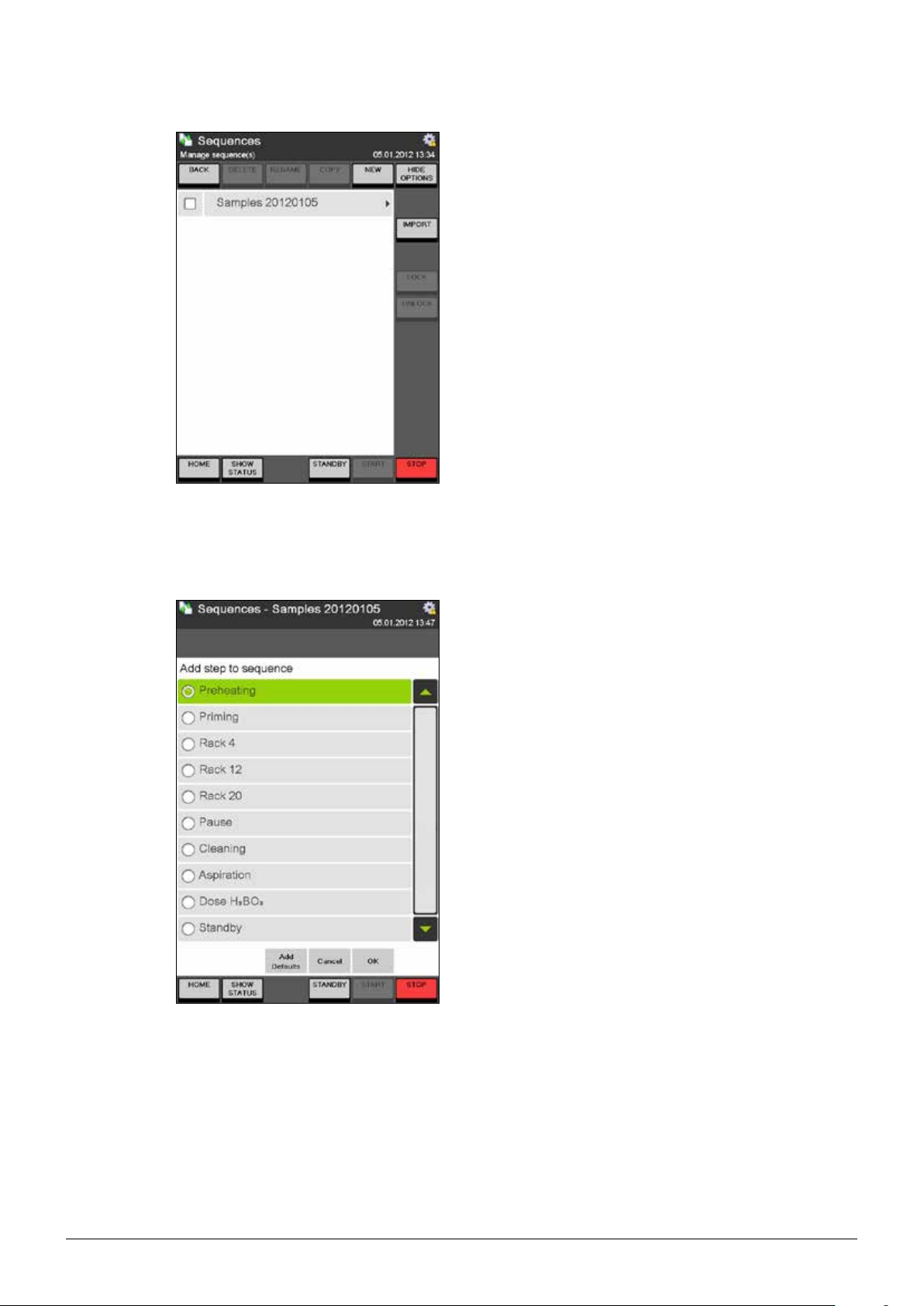
6 Operation
Press the Sequences button.
Under Sequences a list of all present sample
sequences for the sampler is displayed.
New sample sequences can be created with NEW
and existing ones can be deleted, renamed or
copied.
It is also possible to import sample sequences that
have been set up on a personal computer from a
USB device or a network place.
User with administrator rights can also lock and
unlock sample sequences.
NOTE
Locked sequences can not be edited and the
determination of the sample sequence can not be
started.
(screenshot stretched)
Press NEW to create a new sample sequence.
After entering a unique name for the new sequence
either a first single step, or a default set of the five
commonly used steps can be added to the new
sequence (press Add Defaults to add the default
set of steps or select a single step from the list and
press OK).
Additional steps can be entered by pressing NEW.
NOTE
Since the order of the steps can not be changed
afterwards, make sure to add the steps in a reasonable order.
84
K-375/376/377 Operation Manual, Version B
Page 85
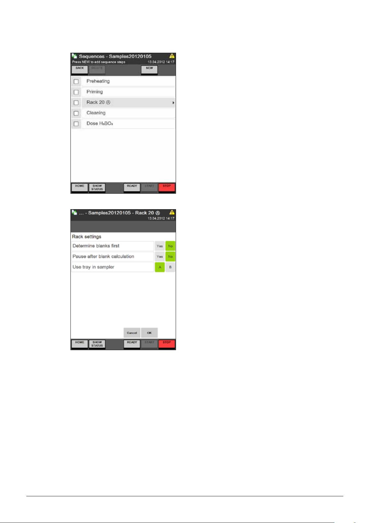
6 Operation
To change the order of steps within a sequence
you have to delete selected steps and to add them
again in a reasonable order.
NOTE
Except the steps “Rack 4“, “Rack 12“, and “Rack
20“ none of the steps can be changed from within
the sequence. (See the table at the beginning of
this chapter for details.)
The tasks Preheating, Priming, and Cleaning are
always performed “via sampler”, if used within a
sequence. Even if those tasks are set to “unit only”
within the “System Preparation” under “Preparative
tasks”, this setting will be omitted.
Click on the Rack step to adapt the settings of the
rack and to add samples to the rack.
Press SETTINGS and adapt the settings for the
rack:
“Determine blanks first” Yes/No
(If blanks are determined first, the risk of a crosscontamination can be minimized for the blanks.)
“Pause after blank calculation” Yes/No
A pause after the blank calculation leaves a user
with operator rights the chance to eliminate a faulty
blank determination from the calculation before
any sample determinations are corrected with the
calculated blank.
The third setting is only available for 2-tray samplers:
“Use tray in sampler” A/B
Define the position of the rack in the K-377 sampler.
The step will be marked with A or B.
85
K-375/376/377 Operation Manual, Version B
Page 86

6 Operation
The positions of the rack can be filled one by one
with samples by clicking on each position.
NOTE
Using the buttons PREVIOUS POSITION and
NEXT POSITION you can switch easily from one
sample to the next/previous within each parameter
screen. Thus each parameter can be adapted for all
samples of the rack in a very easy and convenient
way.
The first parameter for each sample is the sample
type:
• Blank,
• Sample,
• Reference substance or
• Control blank.
Press NEW to enter a sample of the selected type
on the next position without leaving the screen.
With OK the sample is added to the actual position
and the sample list is displayed again.
(According to the selected type of sample, a
different set of parameters is offered.)
For samples of type Blank,
press “Name” and enter a name for the blank result.
Press “Method” and select the method to be used
for the determination of the blank from the list of the
available methods.
Press “Group” and select a result group for the
storage of the result from the list of the available
result groups. (It is also possible to create a new
result group using the New Group button.)
86
K-375/376/377 Operation Manual, Version B
Page 87
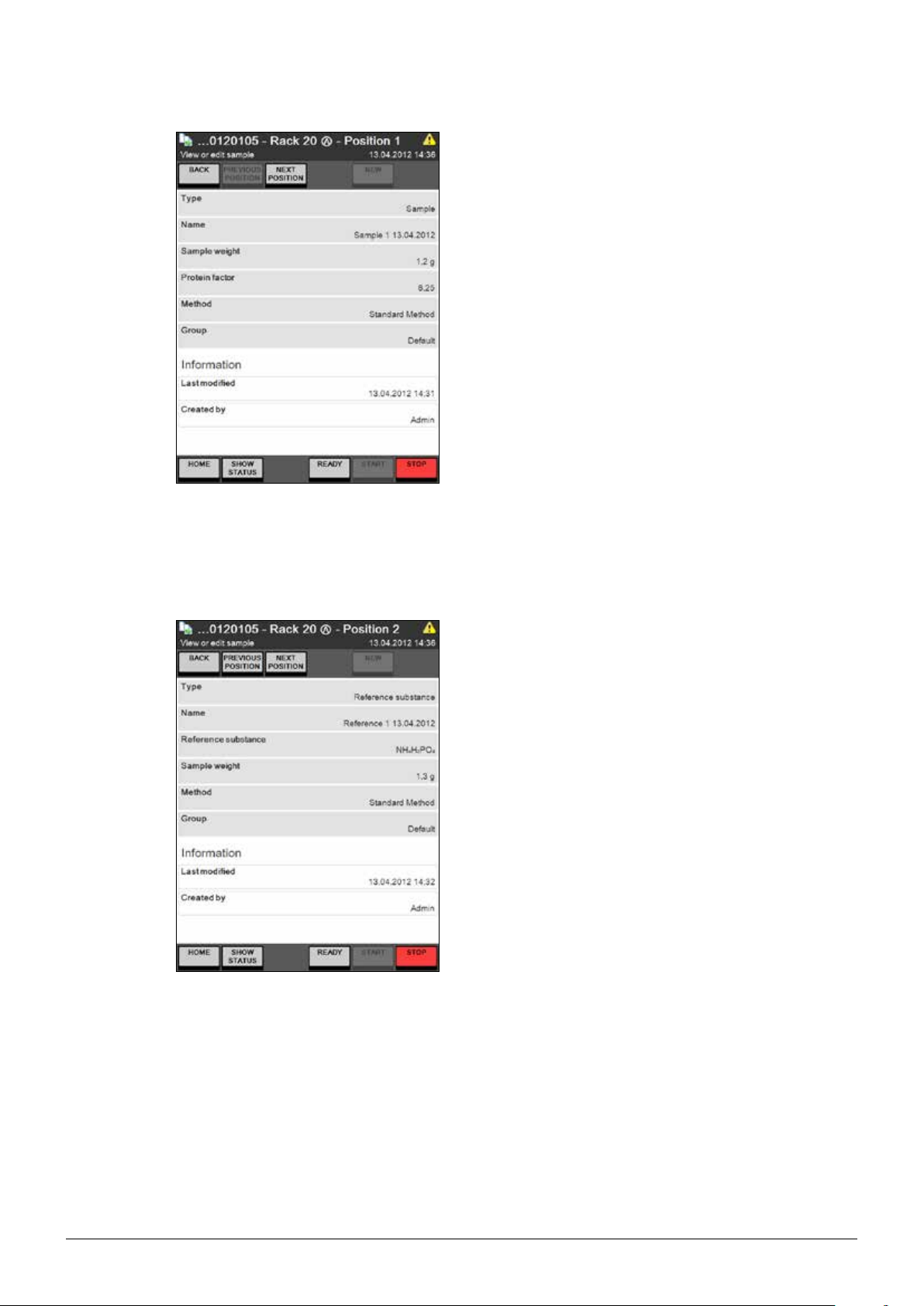
6 Operation
For samples of type Sample,
press “Name” and enter a name for the sample
result.
Press “Sample weight” and enter the weight of the
sample in [g] or [mL].
Press “Protein factor” and enter the protein factor
for the determination of the results.
NOTE
Using a bar code reader it is also possible to read
in every sample related data like name or weight
from a barcode. The read in data is automatically
filled in the active input field.
Press “Method” and select the method to be used
for the sample determination from the list of the
available methods.
Press “Group” and select a result group for the
storage of the result from the list of the available
result groups. (It is also possible to create a new
result group using the New Group button.)
For samples of type Reference Substance,
press “Name” and enter a name for the result of the
reference substance determination.
Press “Reference substance” and select the reference substance from the list.
Press “Sample weight” and enter the weight of the
sample in [g] or [mL].
Press “Method” and select the method to be used
for the determination of the reference substance
from the list of the available methods.
Press “Group” and select a result group for the
storage of the result from the list of the available
result groups. (It is also possible to create a new
result group using the New Group button.)
87
K-375/376/377 Operation Manual, Version B
Page 88
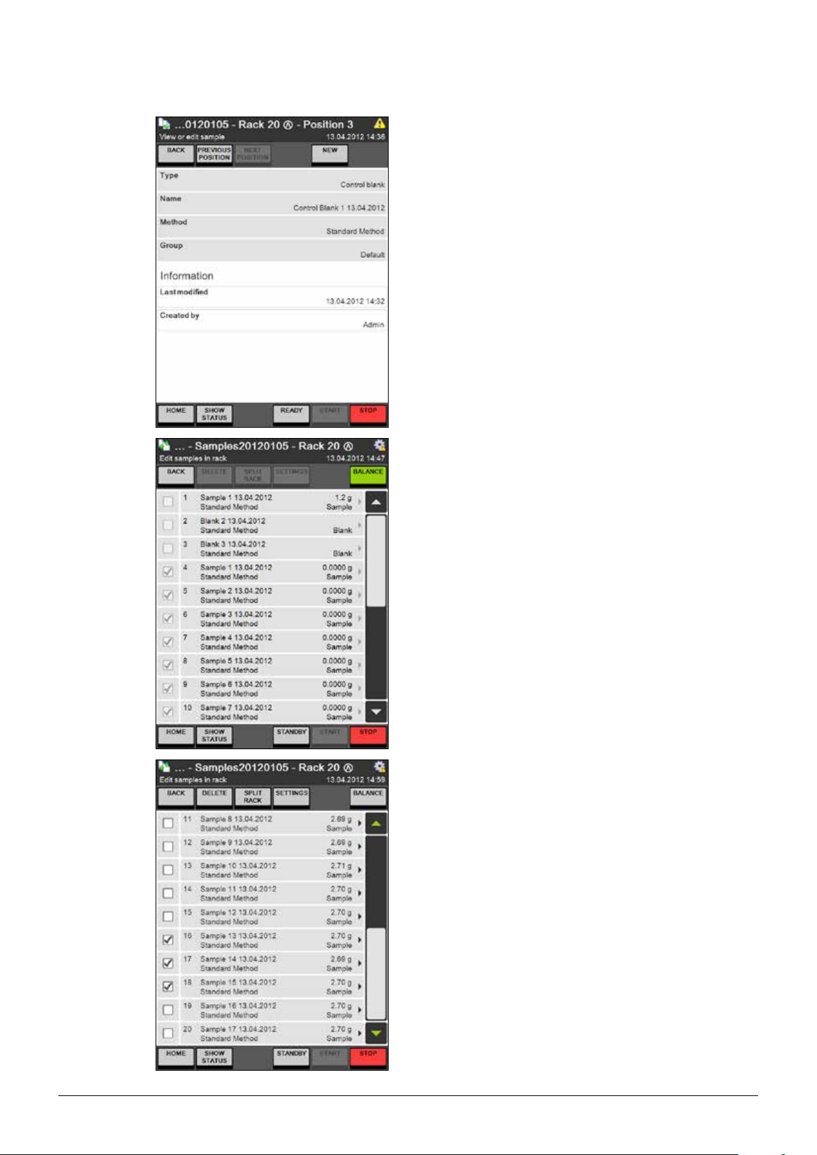
6 Operation
For samples of type Control Blank,
press “Name” and enter a name for the control
blank result.
Press “Method” and select the method to be used
for the determination of the control blank from the
list of the available methods.
Press “Group” and select a result group for the
storage of the result from the list of the available
result groups. (It is also possible to create a new
result group using the New Group button.)
Using the BALANCE button the weight of samples
can be taken over from a connected balance:
• Select all samples
• Press BALANCE – all blanks and control blanks
are automatically deselected (no weight is
needed for blanks)
• Place the first sample on the balance and press
Enter on the balance – the first weight is taken
over from the balance and entered into the first
checked sample in the list.
• Proceed with the next sample
• When all sample weights have been taken over,
the balance mode is automatically left.
If certain samples of a rack that is already in progress have to be determined immediately this can be
done using the Split Rack functionality:
Press PAUSE to stop the determination of the
sequence.
Select the samples to be determined immediately
and press SPLIT RACK.
88
K-375/376/377 Operation Manual, Version B
Page 89
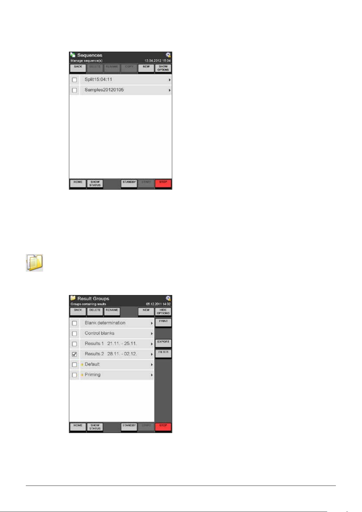
6 Operation
The selected samples will be deleted from the
sequence and will be inserted into the rack-step of
a new created sequence at the same position of the
rack.
The newly created Split-Sequence can be started
to determine express samples – afterwards the
previous sequence can be continued.
NOTE
Using the button EDIT MODE it is possible to edit
samples of a rack that is not yet being processed
during a running sequence.
6.7 Results
In the result area all tasks related to the results (viewing, printing, and exporting) can be performed.
6.7.1 Result groups
As the name implies, result groups are folders in which results can be stored and grouped in accordance with their properties.
The group a result shall be assigned to can be specified using the corresponding sample parameter
“Group” while defining single samples, sample lists or sequences.
The Result Groups screen shows a list of all
present groups, available for the storage of
results.
89
K-375/376/377 Operation Manual, Version B
Page 90

6 Operation
Result groups can be created, renamed and deleted by users with administrator rights. User with
operator rights are only allowed to create new result groups. Using the FILTER button, the list of the
Result groups can be filtered with respect to the name and the creation date of the group:
Set the “Group filter” to On to filter the list of
result groups. Select Yes for “Filter between
dates” if you wish to filter the list with respect to
the creation or rename date and specify a time
period using begin and end date.
Specify a part of the group name as filtering criterion using “Group name contains”.
NOTE
All specified filters are correlated using the logical
”AND” – meaning every condition specified in
the filter settings must apply in order for a group
to match the filter.
Once a filter has been set, the FILTER button is switched to FILTER ACTIVE:
The content of selected groups or selected results can be printed (PRINT) or exported (EXPORT) to
a memory stick or network folder. The path to the network folder and to the target directory on the
memory stick can be defined under Settings Import & Export (see chapter “6.9.1 Settings“).
Just like the list of the result groups, also the list of the contained results can be filtered. Enter a
sample group to set the sample filter:
90
K-375/376/377 Operation Manual, Version B
Page 91

6 Operation
Press FILTER to set the sample filter.
Set the “Sample filter” to On to filter the list of
displayed results. Select Yes for “Filter between
dates” if you wish to filter the list with respect to
the creation date and specify a time period using
begin and end date.
The list of displayed results can be restricted
to one or more certain types of results (blanks,
samples, references, control blanks).
NOTE
All specified filters are correlated using the logical
”AND” – meaning every condition specified in
the filter settings must apply in order for a group
to match the filter.
91
K-375/376/377 Operation Manual, Version B
Page 92

6.7.2 Last Results
The Last Results screen shows a list of the last 40 results of the system, regardless to the type of
the results.
6 Operation
The sample report of selected results can be
printed either detailed or short. Results can be
exported to a USB stick or a network place.
NOTE
The last results are shown regardless of the
result group they are assigned to.
Clicking on a single result opens the detailed sample report:
With PREVIOUS SAMPLE and NEXT SAMPLE
you can navigate back and forth within the
sample reports of the stored samples.
92
K-375/376/377 Operation Manual, Version B
Page 93

6.7.3 Blank Correction
The blank correction can be switched on and off:
HOME Blank Correction SETTINGS
Within the Blank Correction main screen a list of the latest blanks can be viewed. By adapting the
parameter “Blanks in list” under SETTINGS it can be determined how many blanks will be shown in
this list:
6 Operation
ON Blank correction of results is switched on.
OFF Blank correction of results is switched off –
no blank correction at all will be performed.
- Will decrease the number of displayed blanks
by 10.
+ Will increase the number of displayed blanks
by 10.
A maximum number of 90 blanks can be listed.
In general four different possibilities for the determination of the active blank value for the automatic
correction of results are available:
• Blank values can be measured (type: measured).
• Blank values can be entered manually (type: manual).
• Blank values can be calculated as mean value of freely selectable measured blanks (type: mean).
• Blank values can be determined automatically by the system (type: automatic).
The type and the value of the blank currently used for result correction is always displayed in the
results section of the status view:
SHOW STATUS RESULTS (See section 6.5.1)
Entering Manual blanks
To enter a blank value manually (e.g. for a blank value that has not been determined with the instrument), proceed as follows:
Enter the Blank Correction screen.
Press SETTINGS.
93
K-375/376/377 Operation Manual, Version B
Page 94

6 Operation
Within the settings for the blank correction,
• switch “Blank correction” ON
• switch “Auto blank generation” OFF
• select NO for “Use last measured blank”
• confirm your settings with OK.
Press MANUAL
Enter a name for the manual blank value.
Enter the volume for the blank in [mL]
Confirm your settings with OK.
The entered blank value is now automatically selected and shown in the list of blanks in the Blank
Correction screen.
Manually entered blanks are listed in the blank list with type “manual”.
NOTE
If you select Yes for “Use last measured blank“ the next measured value for a sample of Type “Blank“
will be used for the correction of all subsequent sample determinations. All sample determinations up
to the next blank determination will still be corrected using the currently selected blank value.
Defining Mean blanks
Mean blank values can be calculated over two or more measured blank values. To define a Mean
blank value, proceed as follows:
Enter the Blank Correction screen.
Press SETTINGS.
94
K-375/376/377 Operation Manual, Version B
Page 95

6 Operation
Within the settings for the blank correction,
• switch “Blank correction” ON
• switch “Auto blank generation” OFF
• select NO for “Use last measured blank”
• confirm your settings with OK.
Press MEAN
Enter a name for the mean blank value.
Check the check box of those measured blank
values that shall be used for the calculation of the
mean value.
Confirm your selection with OK.
The calculated mean blank value is now automatically selected and shown in the list of blanks in the
Blank Correction screen.
Averaged blanks are listed in the blank list with type “mean”.
NOTE
If you select Yes for “Use last measured blank“ the next measured blank value will be used for the
correction of all subsequent sample determinations. All sample determinations up to the next blank
determination will still be corrected using the currently selected blank value.
95
K-375/376/377 Operation Manual, Version B
Page 96
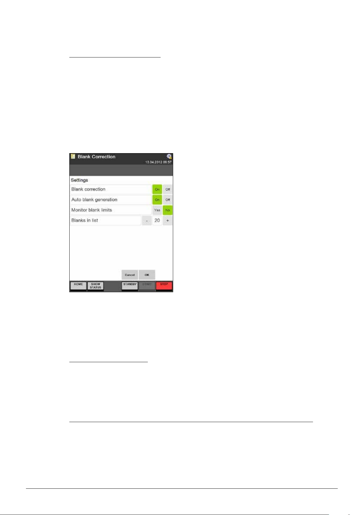
6 Operation
Automatic Blank determination
With automatic blank determination switched on, each continuous row of measured blanks is
automatically averaged and the resulting mean value is used for the correction of the subsequently
measured sample(s). After one or more samples have been determined, the next measured blank (or
the mean of the next measured continuous row of blanks) will be used as active blank value for the
correction of the subsequent samples until the next blank is determined.
Automatically determined blanks are listed in the blank list with type “automatic”.
Enter the Blank Correction screen.
Press SETTINGS.
Within the settings for the blank correction,
• switch “Blank correction” ON
• switch “Auto blank generation” ON
• optionally select YES for “Monitor blank limits”
Set the tolerable range for each blank, compared
with the mean blank value by defining the Upper
and Lower blank limit
• confirm your settings with OK.
The currently active blank can be viewed in the RESULT display of the status view.
NOTE
If you select Yes for “Use last measured blank“ the next measured blank value will be used for the
correction of all subsequent sample determinations. All sample determinations up to the next blank
determination will still be corrected using the currently selected blank value.
Monitoring the blank limits
If the function “Monitor blank limits” is switched on, a tolerable range (defined by the upper- and
lower limit in percent) can be defined for an automatically calculated blank value. Each new determined blank that would be part of this calculation, is compared to the already calculated mean value.
If the deviation of this blank value is outside of the specified range, the sequence is stopped and a
warning message is displayed.
Changing an automatically calculated blank after it was used for sample correction
A user with operator rights is not allowed to change any calculated mean blank value that has already
been used for the correction of any results. Since this proceeding would have an impact to the calculated results this option is restricted to users with administrator rights. Each blank that was changed
subsequently (after it was used for sample correction) is marked with a “*”.
96
K-375/376/377 Operation Manual, Version B
Page 97
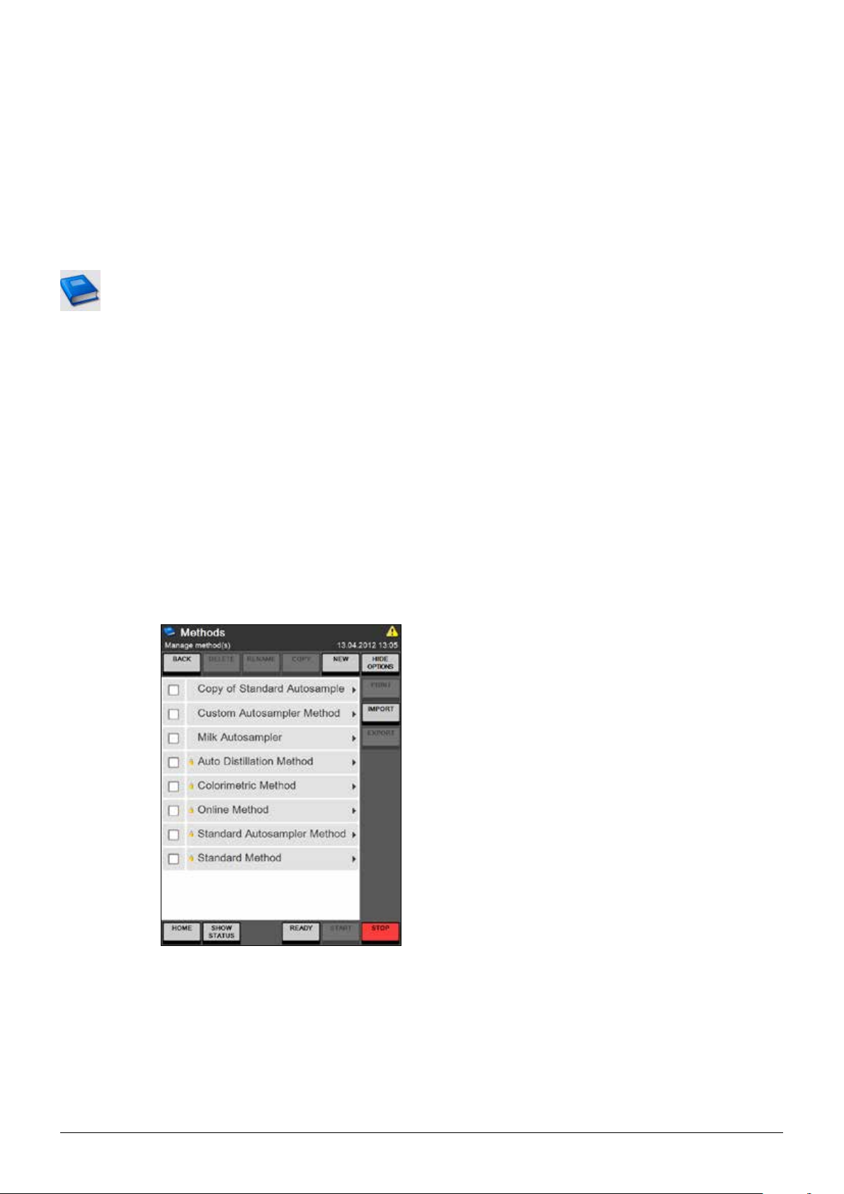
6.8 Determination Parameters
Within this area, the methods for determinations with the K-375 can be written and the resources like
reference substances or volumetric solutions for the titration can be defined and edited.
(Once defined, the resources can be referenced from within the method.)
6.8.1 Methods
The structure of the K-375 method is highly flexible and offers all possibilities to create a method that
reflects the special needs of the user.
Each method consists of 4 different parameter sets:
1. Parameters for the sample distillation
2. Parameters for the sample titration
3. Parameters for the sample determination (calculating the result)
4. Parameters for the aspiration
6 Operation
NOTE
The method does not cover system preparation tasks like Preheating, Priming, and Cleaning – for
single samples or sample lists those tasks have to be performed manually previous to a sample
determination (See chapter “6.6.1 System Preparation“). For sequences (automated determination of sample racks with a sampler) the system preparation tasks can be defined within the Sample
Sequence previous to or after the determination of a complete rack (see chapter “6.6.4 Sequences“).
Within the Methods screen, methods can be
created, deleted, renamed, copied or printed.
A new method is created using the NEW button.
The name for a new method has to be unique.
With the buttons IMPORT and EXPORT, accessible via the SHOW OPTIONS button, methods
can be imported from, or exported to a memory
stick or a network folder.
The path to the network folder and to the target
directory on the memory stick is defined under
Settings Import & Export (see chapter “6.9.1
Settings“).
97
NOTE
Methods marked with a small padlock are predefined and can neither be deleted nor changed.
Nevertheless they can be copied and stored as a
new method which can be changed.
K-375/376/377 Operation Manual, Version B
Page 98
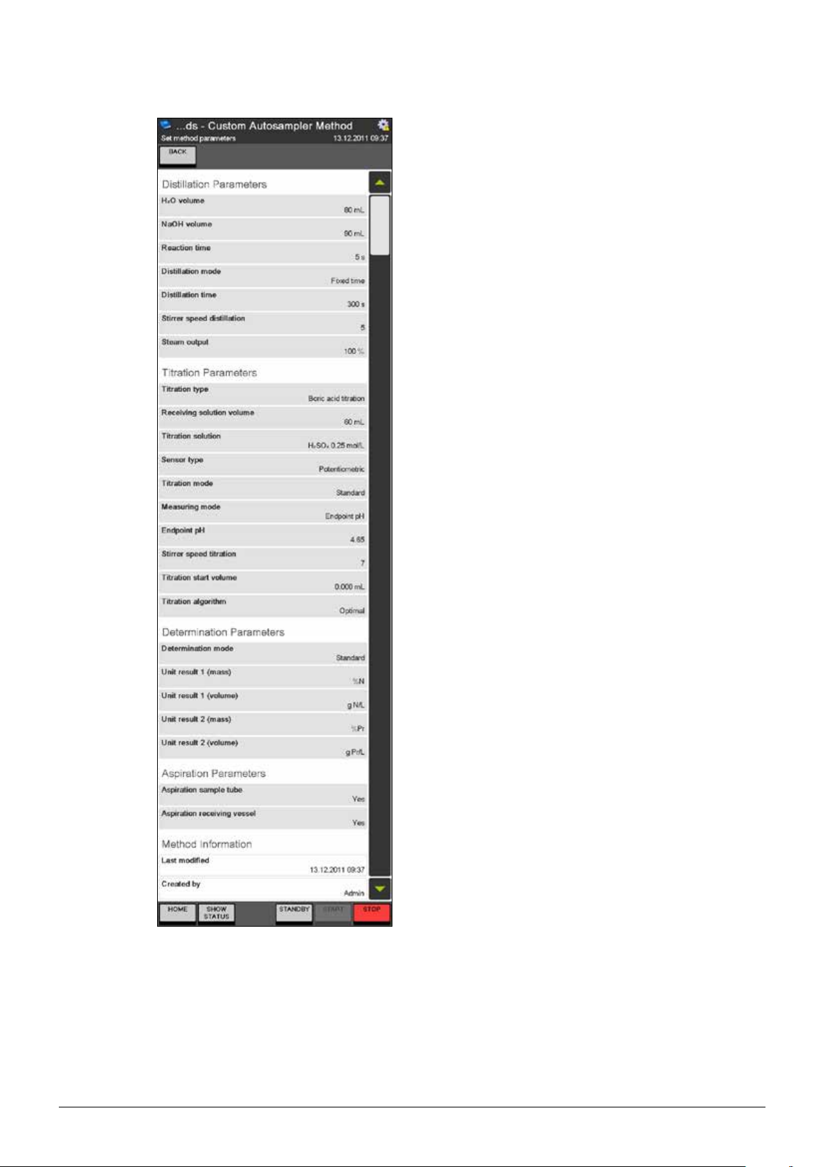
6 Operation
The different areas of the method are separated
from each other by the corresponding heading. The
Method Information section at the bottom of each
method provides information about the last modification date and the creator of the method.
(screenshot stretched)
98
K-375/376/377 Operation Manual, Version B
Page 99
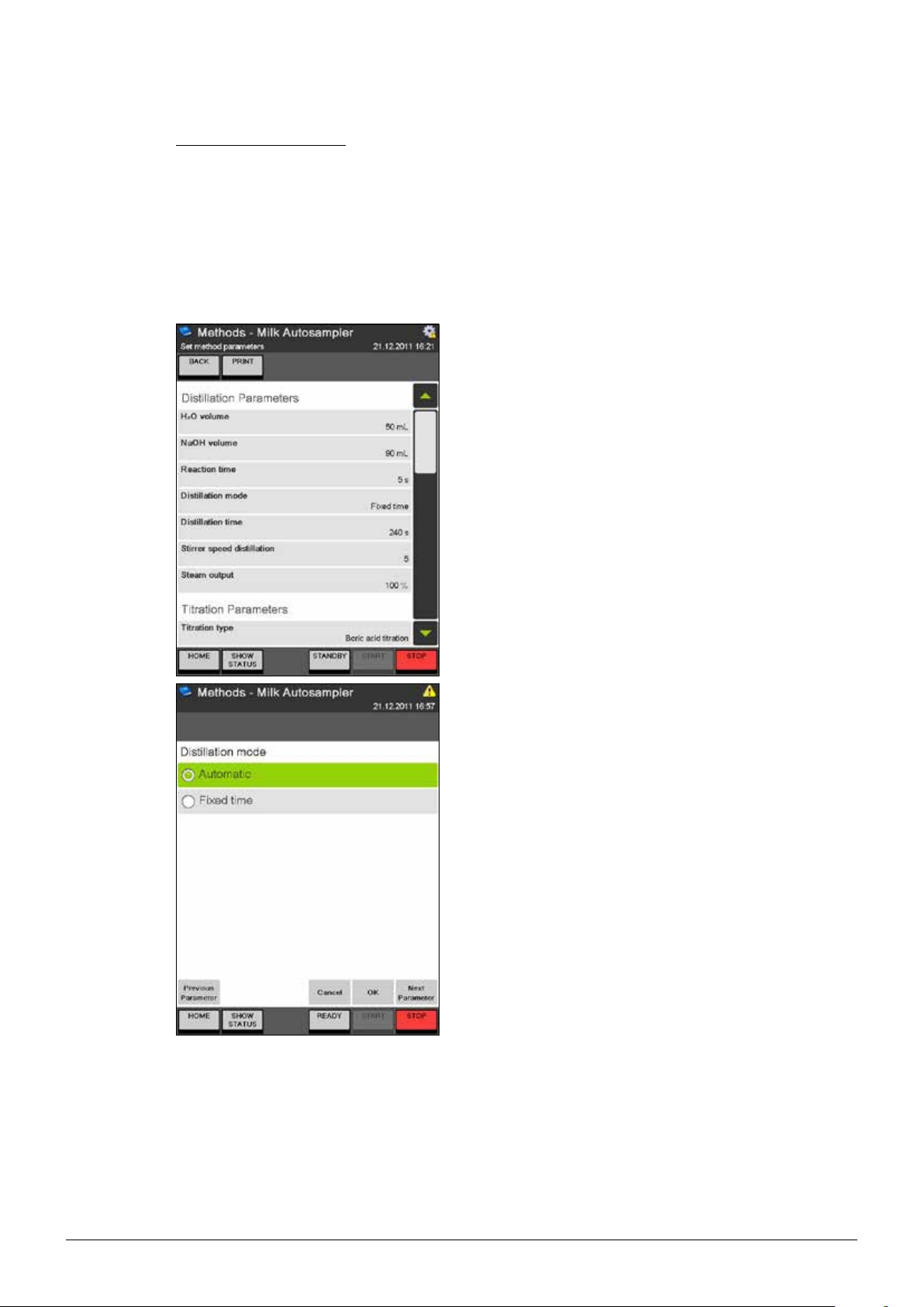
Distillation Parameters
With the distillation parameters all necessary steps for the distillation can be adapted:
Step 1: Dilution with H2O
Step 2: Alkalization with NaOH solution
Step 3: Steam distillation
Parameters for Step 1 and 2 (dilution and alkalization)
Click on “H2O volume“ to specify the volume of
water that shall be used for the dilution of the
sample.
Click on “NaOH volume“ to specify the volume of
the sodium hydroxide solution that shall be used for
the alkalization of the sample. (The concentration of
the sodium hydroxide solution doesn‘t need to be
specified within the instrument. For BUCHI applications a solution of 32 % NaOH is recommended.)
A reaction time for the alkalization can be specified
via the “Reaction time“ button. (Also to allow the
solution to cool down again after the exothermic
neutralization.)
6 Operation
Parameters for Step 3 (Steam distillation)
For the mode of the steam distillation either Automatic (IntelliDist) or Fixed time can be selected.
Automatic: The countdown of the specified distil-
lation time is not started until the first amount of
nitrogen reaches the receiver vessel (indicated by
an increase of the pH value). The variable heat-up
time is excluded from the distillation time. Each
measurement leads to a reliable result – regardless
if performed with a cooled down or a preheated
instrument.
This mode is recommended for all samples
containing more than 1 mg of nitrogen.
The automatic mode cannot be used with colorimetric titrations.
Fixed time: The countdown of the specified distillation time starts at the same time the distillation is
started. Measurements with a cooled down device
will need a longer heat-up time, which will be part
of the specified distillation time.
This mode (together with previous preheating and
priming steps) is recommended for all samples
containing less than 1 mg of nitrogen.
99
K-375/376/377 Operation Manual, Version B
Page 100

6 Operation
After selecting the “Distillation mode”, enter the
distillation time, the stirrer speed during the distillation, and the steam output in percent (between 30
and 100 %).
Titration Parameters
With the first available parameter in this section of the method it can be determined, what kind of
titration shall be performed. Depending on the application either a back titration or a boric acid titration can be performed. BUCHI recommends the use of the boric acid titration.
If no titration at all shall be performed, None can be selected for the parameter “Titration type”. The
boric acid titration can be performed either with a potentiometric or a colorimetric sensor – for the
back titration only the potentiometric sensor can be used.
Select None for the “Titration type”, if no titration at
all shall be performed.
100
K-375/376/377 Operation Manual, Version B
 Loading...