


 Loading...
Operation Manual
Rotavapor®
R 210/215
093076en |

Table of contents
Table of contents
1 |
About this manual . . . . . . . . . . . . . . . . . . |
. . . . . . . . . |
. . . . . . . . . |
. . |
|
. 6 |
|
|
1.1 |
Reference documents |
|
|
|
|
6 |
|
1.2 |
Trademarks . . . . . . . . . . . . |
. . . . . . |
. . . . . . |
. |
. |
6 |
|
1.3 |
Abbreviations . . . . . . . . . . . . |
. . . . . . |
. . . . . . |
. |
|
6 |
2 |
Safety . . . . . . . . . . . . . . . . . . . . . . . . . |
. . . . . . . . . |
. . . . . . . . . |
. . |
|
. 7 |
|
|
2.1 |
User qualification . . . . . . . . . . |
. . . . . . |
. . . . . . |
. |
. |
7 |
|
2.2 |
Proper use . . . . . . . . . . . . |
. . . . . . |
. . . . . . |
. |
. |
7 |
|
2.3 |
Improper use . . . . . . . . . . . . |
. . . . . . |
. . . . . . |
. |
|
7 |
|
2.4 |
Warning notices used in this manual . . . . |
. . . . . . |
. . . . . . |
. |
|
8 |
|
2.5 |
Product safety |
|
|
|
|
8 |
|
2.5.1 |
Instrument-related hazards . . . . . . . |
. . . . . . |
. . . . . . |
. |
|
. 8 |
|
2.5.2 |
Other hazards |
|
|
|
|
9 |
|
2.5.3 |
Safety measures . . . . . . . . . . |
. . . . . . |
. . . . . . |
. |
. |
9 |
|
2.5.4 |
Safety elements |
|
|
|
|
9 |
|
2.6 |
General safety rules . . . . . . . . . . |
. . . . . . |
. . . . . . |
. |
|
10 |
3 |
Technical data . . . . . . . . . . . . . . . |
. . . . . . . |
. . . . . . . |
. |
|
.11. . . . |
|
|
3.1 |
Scope of delivery . . . . . . . . . . |
. . . . . . |
. . . . . . |
. |
. 11 |
|
|
3.1.1 |
Basic instrument . . . . . . . . . . |
. . . . . . |
. . . . . . |
. |
. 11 |
|
|
3.1.2 |
Standard accessories . . . . . . . . . |
. . . . . . |
. . . . . . |
. |
|
12 |
|
3.1.3 |
Optional accessories . . . . . . . . . |
. . . . . . |
. . . . . . |
. |
|
19 |
|
3.1.4 |
Upgrade |
|
|
|
|
22 |
|
3.2 |
Materials used |
|
|
|
|
22 |
|
3.3 |
Technical data overview |
|
|
|
|
23 |
|
3.4 |
Solvent table . . . . . . . . . . . . |
. . . . . . |
. . . . . . |
. |
|
24 |
Read this manual carefully before installing and running your system and note the safety precautions in chapter 2 in particular. Store the manual in the immediate vicinity of the instrument, so that it can be consulted at any time.
No technical modifications may be made to the instrument without the prior written agreement of BUCHI. Unauthorized modifications may affect the system safety or result in accidents.
This manual is copyright. Information from it may not be reproduced, distributed, or used for competitive purposes, nor made available to third parties. The manufacture of any component with the aid of this manual without prior written agreement is also prohibited.
The English manual is the original language version and serves as basis for all translations into other languages. Other language versions can be downloaded at www.buchi.com.
3 |
R-210/215 Operation Manual, Version F |

Table of contents
4 |
Description of function . . . . . . . . . . . . . |
. . . . |
. . . |
. . |
. . |
. |
. . 25. . . . . |
|
|
4.1 |
Functional principle of a Rotavapor . . . . . . |
. . . . |
. . |
. . |
. . |
. |
. 25 |
4.1.1Functional principle considering the V assembly as example . . . . . . . . . 25
|
4.1.2 |
Controls of Rotavapor R-210/215 |
|
|
26 |
|
4.1.3 |
Rear connections of the Rotavapor . . . . . . . . |
. . . . . . . . |
. |
. 27 |
|
4.2 |
Motorized quick-action jack |
|
|
27 |
|
4.3 |
Heating bath . . . . . . . . . . . . . . . . |
. . . . . . . . |
. |
28 |
|
4.4 |
Combi Clip . . . . . . . . . . . . . . . . |
. . . . . . . . |
. |
. 28 |
|
4.5 |
Vapor temperature sensor |
|
|
29 |
|
4.6 |
Protective shield (optional) |
|
|
29 |
|
4.7 |
Valve unit . . . . . . . . . . . . . . . . . |
. . . . . . . . |
. |
30 |
|
4.8 |
Woulff bottle |
|
|
30 |
|
4.9 |
Combination of Rotavapor and vacuum controller |
|
|
30 |
|
4.10 |
Infrared interface . . . . . . . . . . . . . . |
. . . . . . . . |
. |
. 31 |
5 |
Putting into operation . . . . . . . . . . . . . . . . . . . . . . |
. . . . . . . . . . . . |
. . |
32 |
|
|
5.1 |
Installation site |
|
|
32 |
|
5.2 |
Electrical connections |
|
|
32 |
|
5.3 |
Commissioning the heating bath . . . . . . . . . |
. . . . . . . . |
. |
32 |
|
5.3.1 |
Heating Bath B-495 |
|
|
33 |
|
5.3.2 |
Heating medium |
|
|
34 |
|
5.4 |
Glass assembly . . . . . . . . . . . . . . . |
. . . . . . . . |
. |
35 |
|
5.5 |
Installing the condenser and the seal . . . . . . . . |
. . . . . . . . |
. |
35 |
|
5.6 |
Installing the reflux insert . . . . . . . . . . . . |
. . . . . . . . |
. |
36 |
|
5.7 |
Mounting the support rod (optional accessory) . . . . |
. . . . . . . . |
. |
. 36 |
|
5.8 |
Tube connections . . . . . . . . . . . . . . |
. . . . . . . . |
. |
. 37 |
|
5.8.1 |
Connection scheme |
|
|
37 |
|
5.8.2 |
Cooling water tubes |
|
|
38 |
|
5.8.3 |
Vacuum tubes |
|
|
38 |
|
5.8.4 |
Tube connections to the valve unit |
|
|
39 |
|
5.9 |
Installing the vacuum controller . . . . . . . . . . |
. . . . . . . . |
. |
40 |
|
5.10 |
Cable connections to the Rotavapor . . . . . . . . |
. . . . . . . . |
. |
40 |
|
5.11 |
Installing the vapor temperature sensor . . . . . . . |
. . . . . . . . |
. |
41 |
|
5.12 |
Functional test |
|
|
41 |
6 |
Operation . . . . . . . . . . . . . . . . . . . . . |
. . . . . . . . . |
. |
. 42. . . . . |
|
6.1Settings at the heating bath . . . . . . . . . . . . . . . . . . . . . . . . . . . . . . 42
6.1.1 Setting the heating bath temperature . . . . . . . . . . . . . . . . . 42
6.1.2Switching the B-491 from water bath mode to oil bath mode . . . . . . . . . 42
6.1.3Switching the B-491 from oil bath mode to water bath mode . . . . . . . . . 43
6.1.4 |
Selecting the set temperature . . . . . . . . . . . . . . |
. . . . . |
. 43 |
6.1.5 |
Changing/switching off the set temperature |
|
43 |
6.2 |
Immersion angle of the evaporating flask into the heating bath . . |
. . . . . . |
44 |
6.3Lowering and raising the evaporating flask into and out of the heating bath . . . . 45
6.4 |
Selecting the distillation conditions . . . . . . |
. . . . . |
. . . . . . |
|
. 45 |
6.5 |
Distilling . . . . . . . . . . . . . . . . |
. . . . |
. . . . . . |
. |
46 |
6.6 |
Optimizing the distillation conditions |
|
|
|
47 |
6.7 |
When the distillation “dies out” . . . . . . . . |
. . . . |
. . . . . . |
. |
48 |
4 |
R-210/215 Operation Manual, Version F |

Table of contents
7 |
Maintenance . . . . . . . . . . . . . . . . . . . . . |
. . . |
. . . |
. . . . . . . . . |
. . . . . |
49 |
||
|
7.1 |
Housing |
|
|
|
|
|
49 |
|
7.2 |
Tube connections and joints |
|
|
|
|
|
49 |
|
7.3 |
Sealing system . . . . . . . . . . . |
. . |
. . |
. . . . . . |
. . |
. |
49 |
|
7.3.1 |
Cleaning the seals |
|
|
|
|
|
50 |
|
7.3.2 |
Replacing the seals . . . . . . . . . . |
. . |
. . |
. . . . . . |
. . |
. |
50 |
|
7.4 |
Heating bath . . . . . . . . . . . . |
. . |
. . |
. . . . . . |
. . |
. |
50 |
|
7.5 |
Glass components . . . . . . . . . . |
. . |
. . |
. . . . . . |
. . |
. |
50 |
8 |
Troubleshooting . . . . . . . . . . . . . . |
. . . |
. . |
. . . . . . . |
. . |
. . 51. . . . . |
||
|
8.1 |
Malfunctions and their remedy |
|
|
|
|
|
51 |
|
8.2 |
Customer service . . . . . . . . . . |
. . |
. . |
. . . . . . |
. . |
. |
. 54 |
9 |
Shutdown, storage, transport and disposal . . . . |
. . . |
. . . |
. . . . . . . . . |
. . . . . |
55 |
||
|
9.1 |
Storage and transport |
|
|
|
|
|
55 |
|
9.2 |
Disposal |
|
|
|
|
|
55 |
|
9.3 |
Health and safety clearance form . . . . . |
. . |
. . |
. . . . . . |
. . |
. |
56 |
10 |
Spare parts . . . . . . . . . . . . . . . . . . . . . . |
. . . |
. . . |
. . . . . . . . . |
. . . |
. . |
57 |
|
|
10.1 |
Glass assembly A . . . . . . . . . . |
. . |
. . |
. . . . . . |
. . |
. |
. 58 |
|
10.2 |
Glass assembly V . . . . . . . . . . |
. . |
. . |
. . . . . . |
. . |
. |
. 59 |
|
10.3 |
Glass assembly C |
|
|
|
|
|
60 |
|
10.4 |
Glass assembly S . . . . . . . . . . |
. . |
. . |
. . . . . . |
. . |
. |
. 62 |
|
10.5 |
Glass assembly CR . . . . . . . . . . |
. . |
. . |
. . . . . . |
. . |
. |
64 |
|
10.6 |
Glass assembly E . . . . . . . . . . |
. . |
. . |
. . . . . . |
. . |
. |
. 66 |
|
10.7 |
Glass assembly BY . . . . . . . . . . |
. . |
. . |
. . . . . . |
. . |
. |
68 |
|
10.8 |
Sealing system . . . . . . . . . . . |
. . |
. . |
. . . . . . |
. . |
. |
69 |
|
10.9 |
Various glass parts . . . . . . . . . . |
. . |
. . |
. . . . . . |
. . |
. |
70 |
|
10.10 |
Miscellaneous |
|
|
|
|
|
73 |
11 |
Declarations and requirements . . . . . . . . . . . . . . . . . . . . . . . . . . . . . . . 76 |
|||||||
|
11.1 |
FCC requirements (for USA and Canada) . . |
. . |
. . |
. . . . . . |
. . |
. |
. 76 |
|
11.2 |
Declaration of conformity . . . . . . . . |
. . |
. . |
. . . . . . |
. . |
. |
77 |
5 |
R-210/215 Operation Manual, Version F |

1 About this manual
1 About this manual
This manual describes the Rotavapor and provides all information required for its safe operation and to maintain it in good working order.
It is addressed in particular to laboratory personnel and operators.
NOTE
The symbols pertaining to safety (WARNINGS and ATTENTIONS) are explained in chapter 2.
1..1 Reference documents
For information on the Vacuum Controller V-850/855 and the Vacuum Pump V-700/710, please refer to the corresponding manuals available in English, German, French, Spanish and Italian:
•Vacuum Controller, Operating Manual numbers 93081–93085
•Vacuum Pump, Operating Manual numbers 93090–93094
1..2 Trademarks
The following product names and any registered and unregistered trademarks mentioned in this manual are used for identification purposes only and remain the exclusive property of their respective owners:
• Rotavapor® is a registered trademark of BÜCHI Labortechnik AG
1..3 Abbreviations
FFKM: Perfluoroelastomer PTFE: Polytetrafluoroethylene
NBR: Butadiene-acrylonitrile rubber
P+G: PLASTIC + Glass is a unique protective layer for glass components. It offers improved mechanical rupture resistance and increases protection against broken glass. It also makes sure that the sample is not lost in the receiving flask, if the flask is damaged.
PBT: Polybutylene Terephthalate Rpm: Rotations per minute
6 |
R-210/215 Operation Manual, Version F |

2 Safety
2 Safety
This chapter points out the safety concept of the instrument and contains general rules of behavior and warnings from hazards concerning the use of the product.
The safety of users and personnel can only be ensured if these safety instructions and the safetyrelated warnings in the individual chapters are strictly observed and followed. Therefore, the manual must always be available to all persons performing the tasks described herein.
2..1 User qualification
The instrument may only be used by laboratory personnel and other persons who on account of training or professional experience have an overview of the dangers which can develop when operating the instrument.
Personnel without this training or persons who are currently being trained require careful instruction. The present Operation Manual serves as the basis for this.
2..2 Proper use
The instrument has been designed and built for laboratories. It serves for activities associated with evaporation of solvents.
It is used for:
•Distilling solvents
•Vaporizing of solvents
•Recrystallization
•Synthesis and cleaning of chemicals
•Soxhlet extractions
•Drying powders by means of the drying flask
The instrument can only be operated properly together with a heating bath.
2..3 Improper use
Applications not mentioned above are improper. Also, applications, which do not comply with the technical data, are considered improper. The operator bears the sole risk for any damages caused by such improper use.
The following uses are expressly forbidden:
•Use of the instrument in rooms which require ex-protected instruments.
•Use as a calibrating instrument for other instruments.
•Determination of samples, which can explode or inflame (example: explosives, etc.) due to shock, friction, heat or spark formation.
•Use in overpressure situations.
•Use of unappropriate water or oil baths, especially the use of heating sources with temperatures above 180 °C (e.g. a Bunsen burner, etc.).
•Processing of hard, brittle materials (e.g. stones, soil samples, etc.), which can lead to the destruction of the evaporating flask.
•Use with a sample weight of more than 3 kg within the evaporating flask.
7 |
R-210/215 Operation Manual, Version F |

2 Safety
2..4 Warning notices used in this manual
WARNING
Generally, the triangular warning symbol indicates the possibility of personal injury or even loss of life if the instructions are not followed.
WARNING
Hot surface.
WARNING
Electrical hazard.
WARNING
Biohazard.
ATTENTION
With the general “Read this” symbol, ATTENTIONs indicate the possibility of equipment damage, malfunctions or incorrect process results, if instructions are not followed.
NOTE
Useful tips for the easy operation of the instrument.
2..5 Product safety
The Rotavapor is designed and built in accordance with current state-of-the-art technology. Nevertheless, risks to users, property, and the environment can arise when the instrument is used carelessly or improperly.
The manufacturer has determined residual dangers emanating from the instrument
•if the instrument is operated by insufficiently trained personnel.
•if the instrument is not operated according to its proper use.
Appropriate warnings in this manual serve to make the user alert to these residual dangers.
2..5..1 Instrument-related hazards
Pay attention to the following safety notices:
WARNING
Potentially hot surfaces during operation, especially at the water or oil bath (up to 180 °C).
•Always be aware of the risk of being burned.
•When using an oil bath, make sure that no water gets into the bath otherwise there is a serious risk of being splashed by hot oil.
WARNING
Potential implosion risk if used with damaged glassware.
Risk of electrostatic discharge when the rotary evaporator is filled with solvents, e.g. via the feeding tube, or when drying powders are used.
•Beware of damaged or cracked glass parts.
•Beware of the fire hazard.
8 |
R-210/215 Operation Manual, Version F |

2 Safety
WARNING
Potential explosion risk if solvent vapors accumulate within the instrument housing.
•Always use the instrument in a well ventilated area.
•Beware of damaged or cracked glass parts.
•Beware of the fire hazard.
2..5..2 Other hazards
WARNING
Certain solvents in or in the vicinity of the Rotavapor can form peroxides and/or are highly inflammable.
•Always be aware of the explosion risk when working with hazardous substances or with substances of unknown composition.
•Always provide a good ventilation within or in the vicinity of the system.
2..5..3 Safety measures
Always wear personal protective equipment such as protective eye goggles, protective clothing and gloves when working with the instrument.
2..5..4 Safety elements
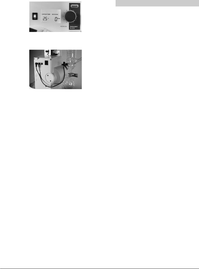
Electronics
•The heating bath is equipped with a mechanical and an electronic over-temperature protection. The mechanical over-temperature protection consists of a bimetal thermostat that, in case of overtemperature (over 260 °C), directly interrupts the power supply. It has to be set back manually after the bath has cooled down (see also chapter 8).
The electronic over-temperature protection controls the temperature limit (actual bath temperature may not exceed the given temperature by 2 °C for more than 2 minutes), the heating rate (actual temperature may not rise by more than 5 °C during 5 seconds) and the function of the temperature sensor.
•The heating bath is equipped with safety fuses.
•Electronic control of the heating bath temperature - to prevent the product from overheating
Parts in direct contact with the instrument
•Safety catch for adjusting the immersion depth of the evaporating flask into the heating bath.
•Combi Clips for fixing the evaporating flask and for safe removal of fixed ground-glass joints.
•Ball joint clip for safe fixing of the receiving flask.
•Rods and holders for fixing the glass assemblies.
•Electronic over-current protection at the drive unit and lift motor.
•Safety spring preventing the vapor duct from dropping out.
•Automatic raising of the flask from the heating bath in case of a power failure.
Glass
•Use of high quality, inert 3.3 borosilicate glass.
•Use of tube clips GL-14 for preventing glass breakage.
9 |
R-210/215 Operation Manual, Version F |

2 Safety
Optional
•P+G is a unique protective layer for glass components. It offers improved mechanical damage resistance and increases protection against broken glass. It also makes sure that the solvent in the receiving flask is not spilling, if the flask is damaged.
•The protective shield (optional accessory) protects operators from broken glass, solvent splashes and hot heating medium in case of accidents or an implosion.
•With the support rod the condenser can additionally be clamped.
2..6 General safety rules
Responsibility of the operator
The head of laboratory is responsible for training his personnel.
The operator shall inform the manufacturer without delay of any safety-related incidents which might occur during operation of the instrument. Legal regulations, such as local, state and federal laws applying to the instrument must be strictly followed.
Duty of maintenance and care
The operator is responsible for ensuring that the instrument is operated in proper condition only, and that maintenance, service, and repair jobs are performed with care and on schedule, and by authorized personnel only.
Spare parts to be used
Use only genuine consumables and genuine spare parts for maintenance to assure good system performance and reliability. Any modifications to the spare parts used are only allowed with the prior written permission of the manufacturer.
Modifications
Modifications to the instrument are only permitted after prior consultation with and with the written approval of the manufacturer. Modifications and upgrades shall only be carried out by an authorized BUCHI technical engineer. The manufacturer will decline any claim resulting from unauthorized modifications.
10 |
R-210/215 Operation Manual, Version F |
3 Technical data
3 Technical data
This chapter introduces the reader to the instrument specifications. It contains the scope of delivery, technical data, requirements and performance data.
3..1 Scope of delivery
Check the scope of delivery according to the order number.
NOTE
For detailed information on the listed products, see www.buchi.com or contact your local dealer.
3..1..1 |
Basic instrument |
|
|||||||||
|
|
Order number: |
|
||||||||
|
|
|
|
|
|
|
|
|
|
|
Rotavapor R-210 |
|
|
2 |
3 |
0 |
x |
x |
x |
x |
x |
x |
|
|
|
|
|
|
|
|
|
|
|
|
|
11 |
R-210/215 Operation Manual, Version F |
Order number:
2 3 1 x x x x x x
Order number:
2 3 2 x x x x x x
Order number:
2 3 3 x x x x x x
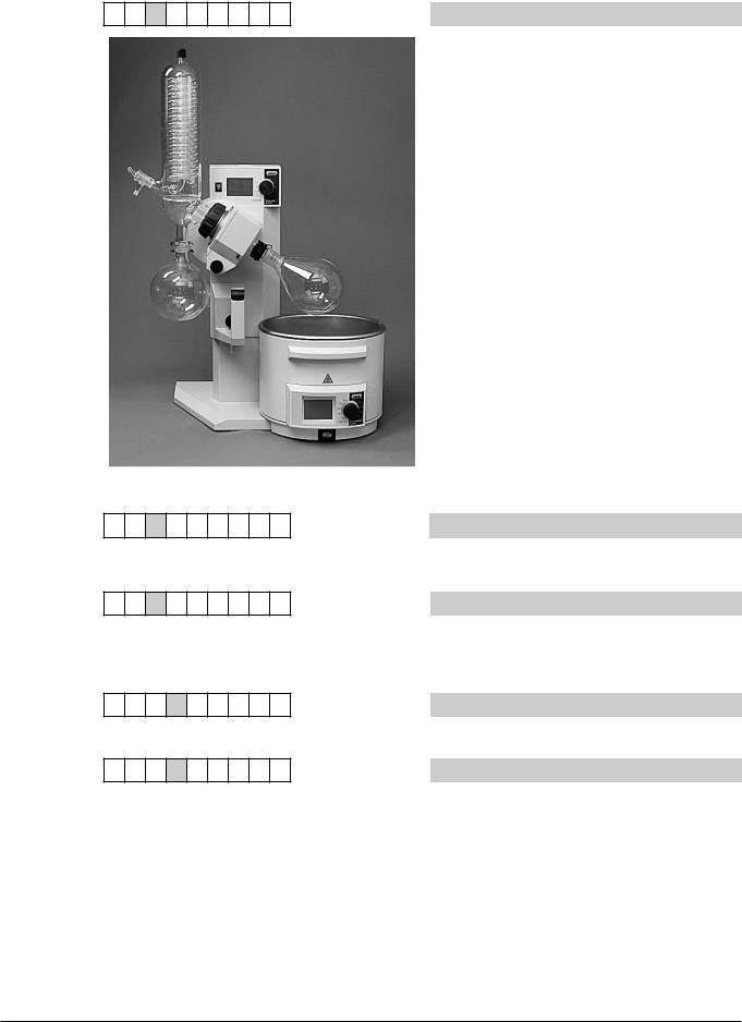
3..1..2 Standard accessories
Order number:
2 3 x 1 x x x x x
Order number:
2 3 x 2 x x x x x
3 Technical data
Rotavapor R-215
The vapor temperature sensor is comprised in the scope of delivery of the condensers V, S, and E.
Rotavapor R-210 without heating bath
Rotavapor R-215 without heating bath
Rotavapor R-210/215 230 V 50/60 Hz
Rotavapor R-210/215 100–120 V 50/60 Hz
12 |
R-210/215 Operation Manual, Version F |

Order number:
2 3 x x 1 x x x x
Order number:
2 3 x x 2 x x x x
Order number:
2 3 x x 3 x x x x
Order number:
2 3 x x x A x x x
Order number:
2 3 x x x V x x x
3 Technical data
Vapor duct SJ 29/32
Vapor duct SJ 24/40
Vapor duct SJ 29/42
Glass assembly A
•Diagonal condenser
•Can be used where height is limited
•For standard distillations
•Evaporating flask feed via stop-cock
Glass assembly V
•Vertical condenser
•Needs little space
•For standard distillations
•Evaporating flask feed via stop-cock
•Connection for vapor temperature sensor
•Auto distillation possible with Auto-distillation probe and Vacuum Controller V-855
13 |
R-210/215 Operation Manual, Version F |

Order number:
2 3 x x x C x x x
Order number:
2 3 x x x S x x x
3 Technical data
Glass assembly C
•Dry ice condenser
•For distillation of solvents with low boiling points
•Evaporating flask feed via stop-cock
•No cooling water necessary
•Maximum condensation due to low temperatures
Glass assembly S
•Vertical condenser with shut-off valve
•For distillations also with reflux
•Evaporating flask feed via stop-cock
•Connection for vapor temperature sensor
•Auto distillation possible with Auto-distillation probe and Vacuum Controller V-855
14 |
R-210/215 Operation Manual, Version F |

Order number:
2 3 x x x E x x x
Order number:
2 3 x x x R x x x
3 Technical data
Glass assembly E
•Descending condenser with expansion vessel
•Ideal for distillations exhibiting foaming or bumping
•Evaporating flask feed via stop-cock
•Connection for vapor temperature sensor
Glass assembly CR
•Dry ice condensation
•For the distillation of solvents with low boiling points also with reflux
•Evaporating flask feed via stop-cock
•No cooling water necessary
•Maximum condensation due to low temperature
15 |
R-210/215 Operation Manual, Version F |
Order number:
2 3 x x x Y x x x
Order number:
2 3 x x x x 1 x x
3 Technical data
Glass assembly BY
•Vertical condenser with additional double jacket for cooling
•Additional joint on the top of the condenser for flexible expansion
•For particularly efficient condensation
•Evaporating flask feed via stop-cock
•Connection for vapor temperature sensor
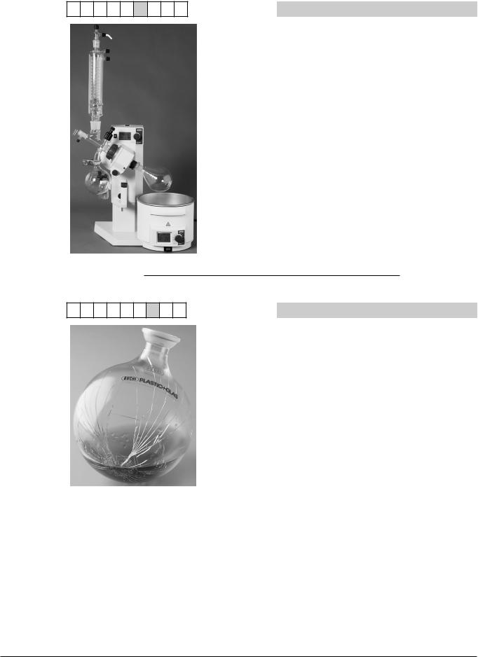
P+G coating
If required, all glass parts can be plastic coated
NOTE
The broken flask shown on the picture on the left demonstrates the function of the P+G coating in case of glass breakage.
16 |
R-210/215 Operation Manual, Version F |

Order number:
2 3 x x x x x 1 x
Order number:
2 3 x x x x x 2 x
3 Technical data
Vacuum Controller V-850, 100–230 V 50/60 Hz
Vacuum Controller V-855, 100–230 V 50/60 Hz
The Auto-distillation probe is comprised in the scope of delivery of the condensers V and S.
Order number: |
|
|
|
|
|
|
||||
|
|
|
|
|
|
|
|
|
|
Woulff bottle |
2 |
3 |
x |
x |
x |
x |
x |
x |
1 |
|
|
|
|
|
|
|
||||||
|
|
|
|
|
|
|
|
|
|
|
17 |
R-210/215 Operation Manual, Version F |

3 Technical data
Order number: |
|
|
|
|
||||||
|
|
|
|
|
|
|
|
|
|
Valve unit |
2 |
3 |
x |
x |
x |
x |
x |
x |
2 |
|
|
|
|
|
|
|
||||||
|
|
|
|
|
|
|
|
|
|
|
Table 3-1: Standard accessories
Product |
Order number |
|
|
Cooling water tube silicone 9/6 mm |
04133 |
|
|
2 power cords |
– |
|
|
Type CH plug type 12 or PNE, 2.5 m |
10010 |
|
|
Type Schuko |
10016 |
|
|
Type GB |
17835 |
|
|
Type AUS |
17836 |
|
|
Type USA |
10020 |
|
|
4 cable binders |
– |
|
|
Operation Manual: |
|
|
|
English |
93076 |
|
|
German |
93077 |
|
|
French |
93078 |
|
|
Italian |
93079 |
|
|
Spanish |
93080 |
|
|
18 |
R-210/215 Operation Manual, Version F |

3 Technical data
3..1..3 Optional accessories
Table 3-2: Optional accessories
Product |
Order number |
|
|
Vacuum Pump V-700 |
71000 |
(100 V–230 V 50/60 Hz) |
|
|
|
Vacuum Pump V-700 (100 V–230 V |
71001 |
50/60 Hz) with secondary condenser and |
|
500 mL receiving flask |
|
|
|
Water jet pump (plastic) |
02913 |
|
|
Water jet pump unit B-767 with 2 |
31357 |
magnetic valves 24 V for pump and |
|
cooling water (with a FFKM backstroke |
|
valve) |
|
|
|
Water jet pump unit B-764 with magnetic |
31358 |
valve 24 V (and a FFKM backstroke valve) |
|
(shown as example on picture on the left) |
|
|
|
Woulff bottle complete including holder |
47170 |
|
|
Woulff bottle glass part, P+G coated |
47233 |
|
|
Holder for Woulff bottle |
47164 |
|
|
Valve unit complete, including holder |
47160 |
|
|
Manometer with needle valve complete |
47291 |
(for manual vacuum control) including support for R-210/215, V-700/710 and V-850/855
19 |
R-210/215 Operation Manual, Version F |

3 Technical data
Table 3-2: Optional accessories (cont.)
Product |
|
Order number |
|
|
|
||
F-1XX 230 V |
|
||
|
|
|
|
F-100 Model |
500 Watt fix at 10 °C |
11056460 |
|
|
|
|
|
F-105 Model |
500 Watt controlled |
11056462 |
|
|
|
|
|
F-108 Model |
800 Watt controlled |
11056464 |
|
|
|
|
|
F-114 Model |
1400 Watt controlled |
11056466 |
|
|
|
||
F-1XX 115 V |
|
||
|
|
|
|
F-100 |
Model |
500 Watt fix at 10 °C |
11056461 |
|
|
|
|
F-105 |
Model |
500 Watt controlled |
11056463 |
|
|
|
|
F-108 |
Model |
800 Watt controlled |
11056465 |
|
|
|
|
F-114 |
Model |
1400 Watt controlled |
11056467 |
|
|
|
|
Vacuum Controller V-850 |
47299 |
|
|
Vacuum Controller V-855 |
47298 |
|
|
Remote control for V-850/855 |
47230 |
|
|
Auto-distillation probe for V-855 (only for 47235 glass assembly V + S)
20 |
R-210/215 Operation Manual, Version F |
3 Technical data
Table 3-2: Optional accessories (cont.)
Product |
Order number |
|
|
Heating bath B-491 with digital display |
|
for 20 °C to 180 °C |
|
Heating bath complete 230 V 50/60 Hz |
48200 |
|
|
Heating bath B-491 complete 100–120 V |
48201 |
50/60 Hz |
|
|
|
Heating bath B-491 for R-200/5 complete |
48212 |
230 V 50/60 Hz |
|
|
|
Heating bath B-491 for R-200/5 complete |
48213 |
(100–120 V 50/60 Hz) |
|
|
|
Heating bath platform for R-200/5 |
47972 |
|
|
Heating Bath B-495 for flask sizes up to |
|
5 l with digital display for 20 °C to 95 °C, |
|
bath replenishment and level adjustment |
|
Heating bath complete 230 V 50/60 Hz |
48240 |
|
|
Heating Bath B-495 complete 100–120 V |
48241 |
50/60 Hz |
|
|
|
Protective shield complete for B-491 |
48052 |
|
|
Stop-position extension |
44466 |
|
|
21 |
R-210/215 Operation Manual, Version F |
3 Technical data
3..1..4 Upgrade
Table 3-3: Upgrade R-210 to R-215 - optional
Product |
Order number |
|
|
Upgrade R-210 to R-215, display for |
48376 |
rotation speed and vapor temperature |
|
(without probe) |
|
Note: |
|
Only to be installed by a BUCHI service |
|
engineer. |
|
|
|
1 sensor for measuring the vapor |
40340 |
temperature (only with R-215 and with |
|
glass assembly V + S + E) |
|
|
|
3..2 |
Materials used |
|
|
|
|
|
|
|
|
Table 3-4: Materials used |
|
|
|
Component |
Material designation |
|
|
|
|
|
|
Housing Rotavapor |
Aluminium |
|
|
|
|
|
|
Guides lift |
Hardened steel/stainless steel |
|
|
|
|
|
|
Casting components |
PBT partially glass reinforced |
|
|
|
|
|
|
Housing bath |
PBT partially glass reinforced |
|
|
|
|
|
|
Bath |
Stainless steel |
|
|
|
|
|
|
Protective ring |
PBT partially glass reinforced |
|
|
|
|
|
|
Protective shield |
Polycarbonate |
|
|
|
|
|
|
Center rotation drive |
Stainless steel |
|
|
|
|
|
|
Condenser flange |
Aluminium |
|
|
|
|
|
|
Seal |
NBR, PFTE |
|
|
|
|
22 |
R-210/215 Operation Manual, Version F |

3 Technical data
3..3 |
Technical data overview |
|
|
|
||
|
|
|
|
|
|
|
|
|
Table 3-5: Technical data |
|
|
|
|
|
|
|
R-210 Rotavapor |
R-215 Rotavapor with |
B-491 Heating bath |
B-495 Heating bath |
|
|
|
without display |
display |
|
|
|
|
|
|
|
|
|
|
|
Glass assemblies |
A, V, C, S, E, CR, BY |
|
|
|
|
|
|
|
|
|
|
|
|
Dimensions ( W x H x D) |
550×575×415 mm |
285×240×300 mm |
310×230×320 mm |
|
|
|
|
|
|
|
|
|
|
Weight |
16–18 kg (depending on the glass |
4 kg |
5 kg |
|
|
|
|
assembly) |
|
|
|
|
|
|
|
|
|
|
|
|
Connection voltage |
100–240 V ±10 % |
|
100–120 V or 220–240 V ±10 % |
|
|
|
|
|
|
|
|
|
|
Mains connection |
3-pole (P, N, E) via power cord |
3-pole (P, N, E) via power cord |
||
|
|
|
|
|
|
|
|
|
Frequency |
50/60 Hz |
|
50/60 Hz |
|
|
|
|
|
|
|
|
|
|
Heating power |
|
|
1300 W |
|
|
|
|
|
|
|
|
|
|
Power consumption |
max. 60 W |
|
max. 1700 W |
|
|
|
|
|
|
|
|
|
|
Installation category |
II |
|
II |
|
|
|
|
|
|
|
|
|
|
Degree of protection |
IP21 |
|
IP21 |
|
|
|
|
|
|
|
|
|
|
Pollution degree |
2 |
|
2 |
|
|
|
|
|
|
|
|
|
|
Rotation speed range |
20–280 rpm |
|
|
|
|
|
|
|
|
|
|
|
|
Flask size |
50–4000 mL |
|
up to 4000 mL |
up to 5000 mL |
|
|
|
|
|
|
|
|
|
Max. flask content |
3 kg |
|
|
|
|
|
|
|
|
|
|
|
|
Temperature control |
|
|
20 °C–180 °C |
20 °C–95 °C |
|
|
range |
|
|
|
|
|
|
|
|
|
|
|
|
|
Display |
|
Rotation speed/ |
Set/ |
|
|
|
|
|
vapor temperature |
actual temperature |
|
|
|
|
|
|
|
|
|
|
Temperature accuracy |
|
|
± 2 °C |
± 3 °C |
|
|
|
|
|
|
|
|
|
Environmental conditions |
for indoor use only |
|
|
|
|
|
Temperature |
5–40 °C |
|
|
|
|
|
Altitude |
up to 2000 m |
|
|
|
|
|
Humidity |
maximum relative humidity 80 % for temperatures up to 31 °C, and then linearly |
|||
|
|
|
decreasing to 50 % at 40 °C |
|
|
|
|
|
|
|
|
|
|
|
|
Bath content |
|
|
4 l |
5 l |
|
|
|
|
|
|
|
|
|
Vacuum tightness of |
5 mbar per 3 minutes at a pressure of |
|
|
|
|
|
system with 1 l evapo- |
<10 mbar |
|
|
|
|
|
rating and 1 l receiving |
|
|
|
|
|
|
flask |
|
|
|
|
|
|
|
|
|
|
|
|
|
Temperature resistance |
ca. –70 °C–60 °C |
|
|
|
|
|
P+G |
|
|
|
|
|
|
|
|
|
|
|
|
|
Temperature resistance |
–80 °C–50 °C |
|
|
|
|
|
P+G low temperature |
|
|
|
|
|
|
|
|
|
|
|
|
|
Temperature resistance |
< 160 °C |
|
|
|
|
|
protective shield |
|
|
|
|
|
|
|
|
|
|
|
23 |
R-210/215 Operation Manual, Version F |

3 Technical data
3..4 |
Solvent table |
|
|
|
|
|
|
|
|
|
|
|
|
|
|
|
|
|
|
Table 3-6: Solvent table |
|
|
|
|
|
|
|
|
Solvent |
Formula |
Molar mass |
Evaporation energy |
Boiling point |
Density in |
Vacuum in mbar for |
|
|
|
|
in g/mol |
in J/g |
at 1013 mbar |
g/cm3 |
boiling point at 40 °C |
|
|
Acetone |
CH3H6O |
58.1 |
553 |
56 |
0.790 |
556 |
|
|
n-amylalcohol, n-pentanol |
C5H12O |
88.1 |
595 |
37 |
0.814 |
11 |
|
|
Benzene |
C6H6 |
78.1 |
548 |
80 |
0.877 |
236 |
|
|
n-butanol |
C4H10O |
74.1 |
620 |
118 |
0.810 |
25 |
|
|
tert. butanol (2-methyl-2-propanol) |
C4H10O |
74.1 |
590 |
82 |
0.789 |
130 |
|
|
Chlorobenzene |
C6H5Cl |
112.6 |
377 |
132 |
1.106 |
36 |
|
|
Chloroform |
CHCl3 |
119.4 |
264 |
62 |
1.483 |
474 |
|
|
Cyclohexane |
C6H12 |
84.0 |
389 |
81 |
0.779 |
235 |
|
|
Diethylether |
C4H10O |
74.0 |
389 |
35 |
0.714 |
atmospheric |
|
|
1,2-dichloroethane |
C2H4Cl2 |
99.0 |
335 |
84 |
1.235 |
210 |
|
|
1,2-dichloroethylene (cis) |
C2H2Cl2 |
97.0 |
322 |
60 |
1.284 |
479 |
|
|
1,2-dichloroethylene (trans) |
C2H2Cl2 |
97.0 |
314 |
48 |
1.257 |
751 |
|
|
Diisopropyl ether |
C6H14O |
102.0 |
318 |
68 |
0.724 |
375 |
|
|
Dioxane |
C4H8O2 |
88.1 |
406 |
101 |
1.034 |
107 |
|
|
DMF (dimethyl-formamide) |
C3H7NO |
73.1 |
|
153 |
0.949 |
11 |
|
|
Acetic acid |
C2H4O2 |
60.0 |
695 |
118 |
1.049 |
44 |
|
|
Ethanol |
C2H6O |
46.0 |
879 |
79 |
0.789 |
175 |
|
|
Ethylacetate |
C4H8O2 |
88.1 |
394 |
77 |
0.900 |
240 |
|
|
Heptane |
C7H16 |
100.2 |
373 |
98 |
0.684 |
120 |
|
|
Hexane |
C6H14 |
86.2 |
368 |
69 |
0.660 |
360 |
|
|
Isopropylalcohol |
C3H8O |
60.1 |
699 |
82 |
0.786 |
137 |
|
|
Isoamylalcohol (3-methyl-1-butanol) |
C5H12O |
88.1 |
595 |
129 |
0.809 |
14 |
|
|
Methylethylketone |
C4H8O |
72.1 |
473 |
80 |
0.805 |
243 |
|
|
Methanol |
CH4O |
32.0 |
1227 |
65 |
0.791 |
337 |
|
|
Methylene chloride, dichloromethane |
CH2CI2 |
84.9 |
373 |
40 |
1.327 |
atmospheric |
|
|
Pentane |
C5H12 |
72.1 |
381 |
36 |
06.26 |
atmospheric |
|
|
n-propylalcohol |
C3H8O |
60.1 |
787 |
97 |
0.804 |
67 |
|
|
Pentachloroethane |
C2HCl5 |
202.3 |
201 |
162 |
1.680 |
13 |
|
|
1,1,2,2-tetra-chloroethane |
C2H2Cl4 |
167.9 |
247 |
146 |
1.595 |
20 |
|
|
Tetrachlorocarbon |
CCl4 |
153.8 |
226 |
77 |
1.594 |
271 |
|
|
1,1,1-trichloroethane |
C2H3Cl3 |
133.4 |
251 |
74 |
1.339 |
300 |
|
|
Tetra-chloro-ethylene |
C2Cl4 |
165.8 |
234 |
121 |
1.623 |
53 |
|
|
THF (tetrahydrofurane) |
C4H8O |
72.1 |
|
67 |
0.889 |
374 |
|
|
Toluene |
C7H8 |
92.2 |
427 |
111 |
0.867 |
77 |
|
|
Trichloroethylene |
C2HCl3 |
131.3 |
264 |
87 |
1.464 |
183 |
|
|
Water |
H2O |
18.0 |
2261 |
100 |
1.000 |
72 |
|
|
Xylene (mixture) |
C8H10 |
106.2 |
389 |
|
|
25 |
|
|
o-xylene |
C8H10 |
106.2 |
|
144 |
0.880 |
|
|
|
m-xylene |
C8H10 |
106.2 |
|
139 |
0.864 |
|
|
|
p-xylene |
C8H10 |
106.2 |
|
138 |
0.861 |
|
24 |
R-210/215 Operation Manual, Version F |
Loading...