


Operation Manual
Mini Spray Dryer B-290
093001 en

|
|
|
|
|
|
|
Table of contents |
Table of contents |
|
|
|
|
|
||
1 |
About this manual . . . . . . . . . . . . . . . . . . . . . . . . |
. . . |
. . . . . . . . . |
. . |
|
. 6 |
|
2 |
Safety . . . . . . . . . . . . . . . . . . . . . . . . . . . . . . . |
. . . |
. . . . . . . . . |
. . |
|
. 7 |
|
|
2.1 |
User qualification . . . . . . . . . . . . . . |
. . |
. . . . . . |
. |
. |
7 |
|
2.2 |
Proper use . . . . . . . . . . . . . . . . |
. . |
. . . . . . |
. |
. |
7 |
|
2.3 |
Improper use . . . . . . . . . . . . . . . . |
. . |
. . . . . . |
. |
|
8 |
|
2.4 |
Safety warnings and safety signs used in this manual . . |
. . |
. . . . . . |
. |
. |
8 |
|
2.5 |
Product safety |
|
|
|
|
10 |
|
2.5.1 |
General hazards |
|
|
|
|
10 |
|
2.5.2 |
Warning labels on housing and assemblies . . . . . . |
. . |
. . . . . . |
. |
|
14 |
|
2.5.3 |
Personal protective equipment . . . . . . . . . . |
. . |
. . . . . . |
. |
|
14 |
|
2.5.4 |
Safety elements and measures . . . . . . . . . . |
. . |
. . . . . . |
. |
|
15 |
|
2.6 |
General safety rules . . . . . . . . . . . . . . |
. . |
. . . . . . |
. |
|
16 |
3 |
Technical data . . . . . . . . . . . . . . . . . . . . |
. . |
. . . . . . . |
. |
|
.17. . . . . . . . . |
|
|
3.1 |
Scope of application and delivery . . . . . . . . . |
. . |
. . . . . . |
. |
|
17 |
|
3.1.1 |
Standard instrument |
|
|
|
|
17 |
|
3.1.2 |
Standard accessories . . . . . . . . . . . . . |
. . |
. . . . . . |
. |
|
18 |
|
3.1.3 |
Standard accessories with the B-290 Advanced . . . . |
. . |
. . . . . . |
. |
|
18 |
|
3.1.4 |
Standard accessories with the B-290 Acid resistant |
|
|
|
|
18 |
|
3.1.5 |
Optional accessories . . . . . . . . . . . . . |
. . |
. . . . . . |
. |
|
19 |
|
3.2 |
Technical data overview |
|
|
|
|
20 |
|
3.3 |
Materials used |
|
|
|
|
21 |
4 |
Description of function . . . . . . . . . . . . . . . . |
. . |
. . . . . . . |
. |
|
. 22. . . . . . . . |
|
|
4.1 |
Functional principle of the drying gas . . . . . . . . |
. . |
. . . . . . |
. |
|
22 |
|
4.2 |
Functional principle of the sample feed and dispersion . . |
. . |
. . . . . . |
. |
|
22 |
|
4.3 |
Outlet filter |
|
|
|
|
23 |
|
4.4 |
Inert Loop B-295 . . . . . . . . . . . . . . |
. . |
. . . . . . |
. |
. 23 |
|
|
4.5 |
Dehumidifier B-296 . . . . . . . . . . . . . . |
. . |
. . . . . . |
. |
|
24 |
|
4.6 |
Spray chilling accessory |
|
|
|
|
25 |
4.7Connected accessories to the Mini Spray Dryer B-290 . . . . . . . . . . . 25
|
4.7.1 |
Feed switch valve and remote control panel |
26 |
|
4.7.2 |
Printer or PC for data output via RS-232 serial port . . . . . . . . . . . . |
26 |
5 |
Putting into operation . . . . . . . . . . . . . . . . . . . . . . . . . . . . . . . . . . . |
. 27 |
|
|
5.1 |
Installation site |
27 |
|
5.2 |
Electrical connections |
27 |
5.3Installing the compressed air maintenance unit and compressor (optional) . . . . 28
5.4 |
Installing the glass assembly . . . . . . . . . . . . . . |
. . |
. . |
. |
. 29 |
5.5 |
Installing the spraying nozzle . . . . . . . . . . . . . . |
. . |
. . |
. |
. 30 |
5.6 |
Installing the filters |
|
|
|
31 |
5.6.1 |
Inlet filter installation |
|
|
|
31 |
5.6.2 |
Outlet filter installation |
|
|
|
31 |
5.6.3 |
PTFE filter membrane installation . . . . . . . . . . . . . |
. . |
. . |
. |
33 |
5.6.4 |
Cleaning filter installation . . . . . . . . . . . . . . . . |
. . |
. . |
. |
34 |
5.7 |
Adjusting the peristaltic pump bed and choosing the feeding tube . . |
. . |
. . |
. |
35 |
5.8 |
Tubing installation . . . . . . . . . . . . . . . . . . |
. . |
. . |
. |
. 37 |
5.9 |
Installing the compressor . . . . . . . . . . . . . . . . |
. . |
. . |
. |
38 |
5.10 |
Quick hose couplings . . . . . . . . . . . . . . . . . |
. . |
. . |
. |
39 |
3 |
B-290 Operation Manual, Version I |

Table of contents
5.11 Installing the Inert Loop B-295 . . . . . . . . . . . . . . . . . . . 39
5.12Dehumidifier B-296 and Inert Loop B-295 combination . . . . . . . . . . . 42
5.13 |
Installing the Dehumidifier B-296 . . |
. . . . . . . . . . . |
. . |
. . |
. |
42 |
5.14 |
Installing the Spray Chilling Accessory |
|
|
|
|
44 |
5.15 |
Installation check . . . . . . . . |
. . . . . . . . . . |
. . |
. . |
. |
. 45 |
5.16Additional cleaning measures for food, pharma and cosmetic applications . . . . 46
|
5.16.1 |
Primary cleaning |
|
|
|
46 |
6 |
Operation . . . . . . . . . . . . . . . . . . . . . |
. . . . . . . |
. . |
. |
. 47. . . . . . . . . . |
|
|
6.1 |
Layout of the operating and display elements . . . . . |
. . . . . . |
. . |
. |
48 |
|
6.2 |
Conversion tables for the parameters . . . . . . . . |
. . . . . . |
. . |
. |
49 |
|
6.2.1 |
Flow meter spraying air (rotameter) . . . . . . . . |
. . . . . . |
. . |
. |
. 49 |
|
6.2.2 |
Peristaltic pump |
|
|
|
49 |
|
6.2.3 |
Aspirator . . . . . . . . . . . . . . . . . |
. . . . . . |
. . |
. |
50 |
|
6.3 |
Spray process |
|
|
|
50 |
|
6.4 |
Optimizing parameters . . . . . . . . . . . . |
. . . . . . |
. . |
. |
. 51 |
|
6.5 |
End of spray process . . . . . . . . . . . . . |
. . . . . . |
. . |
. |
51 |
|
6.6 |
Recovering particles of the outlet filter |
|
|
|
51 |
|
6.7 |
Operation with the Inert Loop B-295 . . . . . . . . |
. . . . . . |
. . |
. |
53 |
|
6.7.1 |
Status messages . . . . . . . . . . . . . . |
. . . . . . |
. . |
. |
. 54 |
|
6.8 |
Operation with the Spray Chilling Accessory |
|
|
|
55 |
|
6.9 |
Mini Spray Dryer B-290 acid resistant |
|
|
|
56 |
7 |
Maintenance and repairs . . . . . . . . . . . . . . . |
. . . . . . . |
. . |
. |
. 57. . . . . . . . |
|
|
7.1 |
Housing |
|
|
|
58 |
|
7.2 |
Glass assembly, tubes |
|
|
|
58 |
|
7.3 |
Nozzles . . . . . . . . . . . . . . . . . . |
. . . . . . |
. . |
. |
58 |
|
7.4 |
Aspirator cleaning |
|
|
|
59 |
|
7.5 |
Inert Loop B-295 and Dehumidifier B-296 |
|
|
|
59 |
|
7.6 |
Outlet filter |
|
|
|
60 |
|
7.7 |
Calibrating the oxygen sensor of the Inert Loop B-295 . . |
. . . . . . |
. . |
. |
60 |
|
7.8 |
Replacing the oxygen sensor of the Inert Loop B-295 |
|
|
|
61 |
|
7.9 |
Spray chilling accessory |
|
|
|
61 |
|
7.10 |
Customer service . . . . . . . . . . . . . . |
. . . . . . |
. . |
. |
. 61 |
8 |
Troubleshooting . . . . . . . . . . . . . . . . . . . |
. . . . . . . |
. . |
. |
. 62. . . . . . . . . |
|
|
8.1 |
Error messages and their remedy . . . . . . . . . |
. . . . . . |
. . |
. |
62 |
|
8.2 |
Malfunctions and their remedy |
|
|
|
63 |
9 |
Shutdown, storage, transport and disposal . . . . . . . . . . |
. . . . . . . . . |
. . . . . |
65 |
||
|
9.1 |
Storage and transport |
|
|
|
65 |
|
9.2 |
Disposal |
|
|
|
65 |
10 |
Spare |
parts . . . . . . . . . . . . . . . . . . . . . . . . . . . . |
. . . . . . . . . |
. . . |
. . |
66 |
|
10.1 |
Spray nozzle . . . . . . . . . . . . . . . . |
. . . . . . |
. . |
. |
66 |
|
10.2 |
Glass parts . . . . . . . . . . . . . . . . |
. . . . . . |
. . |
. |
. 70 |
|
10.3 |
Filters . . . . . . . . . . . . . . . . . . |
. . . . . . |
. . |
. |
. 72 |
|
10.4 |
Tubings and connectors |
|
|
|
72 |
|
10.5 |
Trolley . . . . . . . . . . . . . . . . . . |
. . . . . . |
. . |
. |
. 73 |
|
10.6 |
Measurement pipe for gas flow . . . . . . . . . . |
. . . . . . |
. . |
. |
73 |
|
10.7 |
Feed switch valve . . . . . . . . . . . . . . |
. . . . . . |
. . |
. |
. 74 |
|
10.8 |
Remote control panel . . . . . . . . . . . . . |
. . . . . . |
. . |
. |
74 |
|
10.9 |
Inert Loop B-295 . . . . . . . . . . . . . . |
. . . . . . |
. . |
. |
. 74 |
|
10.10 |
Cylinder insulation |
|
|
|
75 |
|
10.11 |
Spray chilling accessory |
|
|
|
76 |
4 |
B-290 Operation Manual, Version I |

Table of contents
10.12 |
Decontamination Glass-Set and sterile filter . . . . |
. . . . . . . . . . . 77 |
10.13 |
Acid resistant accessories |
78 |
11 Declarations and requirements . . . . . . . . . . . . . . . |
. . . . . . |
. . . . . . |
. |
. . |
. |
79 |
||
11.1 |
FCC requirements (for USA and Canada) . . . . |
. |
. . . . |
. . . . |
|
. . |
|
. 79 |
11.2 |
Declaration of conformity . . . . . . . . . . |
|
. . . . |
. . . . |
. |
. |
. |
80 |
11.3 |
Safety certificate |
|
|
|
|
|
|
81 |
11.4 |
Health and safety clearance |
|
|
|
|
|
|
82 |
5 |
B-290 Operation Manual, Version I |

1 About this manual
1 About this manual
This manual describes the Mini Spray Dryer B-290 and its optional accessories and provides all information required for its safe operation and to maintain it in good working order.
It is addressed to laboratory personnel and operators in particular.
Read this manual carefully before installing and running your system and note the safety precautions in chapter 2 in particular. Store the manual in the immediate vicinity of the instrument, so that it can be consulted at any time.
No technical modifications may be made to the instrument without the prior written agreement of BUCHI. Unauthorized modifications may affect the system safety or result in accidents. Technical data are subject to change without notice.
NOTE
The symbols pertaining to safety are explained in chapter 2.
This manual is copyright. Information from it may not be reproduced, distributed or used for competitive purposes, nor made available to third parties. The manufacture of any component with the aid of this manual without prior written agreement is also prohibited.
The English manual is the original language version and serves as basis for all translations into other languages. If you need another language version of this manual, you can download other versions at www.buchi.com or reorder manuals from a BUCHI representative.
Abbreviations
EPDM: Ethylene Propylene Dimonomer
FFKM: Perfluoroelastomers
FPM: Fluoroelastomer
PEEK: Polyetheretherketone
PTFE: Polytetrafluoroethylene
POM: Polyoxymethylene
PFA: Perfluoroalkoxy
6 |
B-290 Operation Manual, Version I |

2 Safety
2 Safety
This chapter highlights out the safety concept of the instrument and contains general rules of behavior and warnings from direct and indirect hazards concerning the use of the product.
For the users safety, all safety instructions and safety messages in the individual sections shall be strictly observed and followed. Therefore, the manual must always be available to all persons performing any tasks described herein.
2..1 User qualification
The instrument is designed and built in accordance with state-of-the-art technology. Nevertheless, risks to users, property, and the environment can arise when the instrument is used carelessly or improperly. The manufacturer has determined residual dangers emanating from the instrument
•if the instrument is operated by insufficiently trained personnel without supervision.
•if the instrument is not operated according to its proper use.
Appropriate warnings in this manual serve to make the user alert to these residual hazards. Personnel without this training or persons who are currently being trained require careful instruction. The present Operation Manual serves as the basis for this.
2..2 Proper use
The Mini Spray Dryer B-290 has been designed and built as laboratory instrument and for batch production. It serves to spray-dry aqueous solutions or suspensions in one operating process. In combination with the Inert Loop B-295, it is possible to work with organic solvents in “closed mode”. Processing in “closed mode” requires N2 or CO2 as an inert gas.
The output particle size of the Mini Spray Dryer B-290 is between 2–25 µm. Thus, the instrument is suited to generate particles in the inhalable size range from a solution of suspension.
•If the instrument is used with potentially toxic or hazardous substances in ‘open mode’, it has to be installed inside a closed fume hood or glove box. In such cases, the complete processing and system handling has to be performed within the ventilated box to avoid toxication and other hazardous situations to the user and the environment.
•Spray drying of corrosive samples require handling in a closed fume hood. An acid proof system in open loop is a variant of the Mini Spray Dryer B-290.
•In any case, all exhausts leaving the exhaust gas tubing have to be lead away instantly by a ventilation system, to remove possibly hazardous substances and fumes from the working area. The ventilation system has to be equipped with safety measures such as outlet filters to avoid contamination of the environmen.
•Operation and handling can require additional personal protective equipment. Operate the instrument with respect to standard laboratory safety rules (i.e. as stated in the latest version of the WHO “Laboratory biosafety manual”) at all times.
•If the Mini Spray Dryer B-290 is used in combination with other instruments (e.g. Chiller) all related manuals are to be fully observed.
•Electrostatic charges are to be arrested from both the product collection vessel and the cyclone via the standard grounding cable if the cyclone is equipped with a grounding socket.
•If the instrument is used for food, pharma and cosmetic products additional cleaning measures (primary cleaning and in place disinfection) are required (see chapter 5.7).
7 |
B-290 Operation Manual, Version I |

2 Safety
2..3 Improper use
Applications not mentioned in section 2.2 are considered to be improper. Also, applications which do not comply with the technical data (see section 3 of this manual) are considered to be improper. The operator bears the sole risk for any damages or hazards caused by such improper use.
The following uses are expressly forbidden:
•Use of gases with unknown chemical composition.
•Spray drying of biohazardous materials such as viruses or bacteria.
•Spray drying of organic solvents without safety lamella curtain, Inert Loop B-295 and in open mode.
•Use of the instrument in rooms which require ex-protected instruments.
•Spray drying of substances which might explode or ignite due to the processing and the selected parameters of the Mini Spray Dryer B-290 or installed sub systems.
•Spray drying of toxic substances.
•Use of samples which might produce oxygen during the processing.
•Unattended use.
2..4 Safety warnings and safety signs used in this manual
DANGER, WARNING, CAUTION and NOTICE are standardized signal words for identifying levels of hazards and risks related to personal injury and property damage. All signal words, which are related to personal injury are accompanied by the general safety sign.
For your safety it is important to read and fully understand the table below with the different signal words and their definitions!
Sign |
Signal word |
Definition |
Risk level |
|
|
DANGER |
Indicates a hazardous situation which, if not avoided, will |
|
|
|
result in death or serious injury. |
|||
|
|
|
||
|
|
|
|
|
|
WARNING |
Indicates a hazardous situation which, if not avoided, could |
|
|
|
result in death or serious injury. |
|||
|
|
|
||
|
|
|
|
|
|
CAUTION |
Indicates a hazardous situation which, if not avoided, may |
|
|
|
result in minor or moderate injury. |
|||
|
|
|
||
|
|
|
|
|
no |
NOTICE |
Indicates possible property damage, but no practices |
|
|
related to personal injury. |
(property damage only) |
|||
|
|
|||
|
|
|
||
|
|
|
|
Supplementary safety information symbols may be placed in a rectangular panel on the left to the signal word and the supplementary text (see example below).
Space for |
! |
SIGNAL WORD |
|
supplementary |
|
||
Supplementary text, describing the kind and level of hazard/risk seriousness. |
|||
safety |
• List of measures to avoid the herein described, hazard or hazardous situation. |
||
information |
|||
• ... |
|
||
symbols. |
|
||
• ... |
|
||
|
|
||
|
|
|
|
8 |
B-290 Operation Manual, Version I |

2 Safety
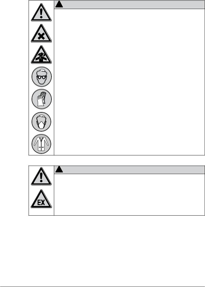
Table of supplementary safety information symbols
The reference list below incorporates all safety information symbols used in this manual and their meaning.
Symbol Meaning
General warning
Electrical hazard
Heavy weight, avoid over exertion
Explosive gases, explosive environment
Harmful to life-forms
Hot item, hot surface
Device damage
Inhalation of substances
Chemical burns by corrosives
Fragile components
Wear laboratory coat
|
|
|
|
|
9 |
|
|
|
B-290 Operation Manual, Version I |

2 Safety
Wear protective goggles
Wear protective mask
Wear protective gloves
Additional user information
Paragraphs starting with NOTE transport helpful information for working with the device/software or its supplementaries. NOTEs are not related to any kind of hazard or damage (see following example).
NOTE
Useful tips for the easy operation of the instrument/software.
2..5 Product safety
Safety warnings in this manual (as described in section 2.4) serve to make the user alert and to avoid hazardous situations emanating from residual dangers by giving appropriate counter measures. However, risks to users, property and the environment can arise when the instrument is damaged, used carelessly or improperly.
2..5..1 General hazards
The following safety messages show hazards of general kind which may occur when handling the instrument. The user shall observe all listed counter measures in order to achieve and maintain the lowest possible level of hazard.
Additional warning messages can be found whenever actions and situations described in this manual are related to situational hazards.
!DANGER
Death by suffocation or serious poisoning by inhalation of inert gases.
•Do not inhale inert gases
•Directly withdraw released gases and gaeous substances by sufficient ventilation
•Only operate the instrument in ventilated environments
• Before opertation, check all parts, connections and sealings involved in the gasflow for proper sealing
•Exchange worn out or defective parts immediately
10 |
B-290 Operation Manual, Version I |
2 Safety
! |
DANGER |
Death or serious poisoning by gases or particles due to O2- sensonr or filter malfunction |
|
• Exchange defective O2-sensor immediately |
|
• Exchange O2-sensor regularly within the specified maintenance intervals |
|
• Exchange clogged filters immediately |
|
• Exchange filters regularly within the specified maintenance intervals |
|
• Dispose of filter immediately |
|
!DANGER
Death or serious poisoning by inhalation or incorporation of dried particles during spray process.
•Wear safety goggles
•Wear safety gloves
•Wear a suitable protective mask
•Wear a laboratory coat
•Check for proper sealing before use
•Do not inhale dried particles
•Stop drying gas flow before opening the drying circuit
|
|
|
|
|
11 |
|
|
|
B-290 Operation Manual, Version I |
2 Safety
!DANGER
Death or serious posioning by inhalation or incorporation of dried particles at recovery.
•Wear safety goggles
•Wear safety gloves
•Wear a suitable protective mask
•Wear a laboratory coat
•Do not inhale dried particles
•Stop drying gas flow before opening the drying circuit
•Only recover particles in sufficiently ventilated flue or glove-box
•Do not disperse the dried particles
•Do not clean dusty parts with compressed air
!WARNING
Death or serious injuries by use in explosive environments.
•Do not operate the instrument in explosive environments
•Do not operate the instrument with explosive gas mixtures
•Before operation, check all gas connections for correct installation
•Directly withdraw released gases and gaseous substances by sufficient ventilation
12 |
B-290 Operation Manual, Version I |

2 Safety
!WARNING
Death or serious poisoning by contact or incorporation of harmful substances at use.
•Before operation, check the instrument for correct assembling
•Before operation, inspect sealings and tubes for good condition
•Exchange worn out or defective parts immediately
•Exchange clogged filters immediately
•Only operate the instrument in ventilated environments
•Directly withdraw released gases and gaseous substances by sufficient ventilation
•Perform a dry-run without sample material and check for gas leakages
!CAUTION
Risk of minor poisoning by inhalation of ozone.
•Directly withdraw released gases and gaseous substances by sufficient ventilation
!CAUTION
Risk of minor or moderate burnings when handling hot parts.
•Do not touch hot parts
•Let the system cool down for some minutes after use
!NOTICE
Risk of instrument short-circuits and damage by liquids.
•Do not spill liquids over the instrument or its component parts
•Wipe off any liquids instantly
•Place the sample vessel onto the designated reservoir-plate on top of the instrument
•Ensure a safe positioning of the sample vessel
•Do not move the instrument when it is loaded with liquid
•Keep external vibrations away from the instrument
!NOTICE
Risk of instrument damage by internal overpressure.
•External supply pressure must meet the system specifications
•Exchange clogged filters immediately
•Dispose of filter immediately
13 |
B-290 Operation Manual, Version I |

2 Safety
!NOTICE
Risk of instrument damage by wrong mains supply.
•External mains supply must meet the voltage given on the type plate
•Check for sufficient grounding
2..5..2 Warning labels on housing and assemblies
The following warning sticker(s) can be found on the housing or assemblies of the Mini Spray Dryer B-290 and Inert Loop B-295:
Symbol |
Meaning |
|
Do not touch |
|
hot item, hot |
|
surface! |
Location
Label, located at the spray cylinder, B-290
See text |
Sticker at the rear side, B-290 |
|
|
|
|
|
|
|
|
|
See text |
Sticker/label, located on the B-295 |
|
|
|
|
|
|
|
|
|
||
|
|
|
|
|
|
|
|
|
||
|
|
|
|
|
|
|
|
|
||
|
|
|
|
|
|
|
|
|
||
|
|
|
|
|
|
|
|
|
||
|
|
|
|
|
|
|
|
|
||
|
|
|
|
|
|
|||||
|
|
|
|
|
|
|||||
|
|
|
|
|
|
|
|
|
|
|
|
|
|
|
|
|
|
|
|
|
|
|
|
|
|
|
|
|
|
|
|
|
|
|
|
|
|
|
|
|
|
|
|
|
|
|
|
|
|
|
|
|
|
|
|
|
|
|
|
|
|
|
|
|
|
|
|
|
|
|
|
|
|
|
|
|
|
|
|
|
|
|
|
|
|
|
|
|
|
|
|
|
|
|
|
|
|
|
2..5..3 Personal protective equipment
Always wear personal protective equipment such as protective eye goggles, protective clothing and gloves. Wear protective mask to protect from inhalation of fine particles. The personal protective equipment must meet all requirements of all data sheets for the chemicals used. These instructions are an important part of the instrument and must be made available at all times to the operating personnel at the place where the equipment is deployed. Additional protective measures can
be necessary according to the applications! The user is fully responsible for choosing adequate measures!
14 |
B-290 Operation Manual, Version I |

2 Safety
!WARNING
Serious chemical burns by corrosives.
•Observe all data sheets of the used chemicals
•Handle corrosives in well ventilated environments only
•Always wear protective goggles
•Always wear protective gloves
•Always wear protective clothes
•Do not use damaged glassware
•Wear protective mask when working with inhalable particles
2..5..4 Safety elements and measures
To arrest electrostatic charges from the instrument, it is internally grounded. Electrostatic charges are to be arrested from both the product collection vessel via the external (yellow) grounding cable for all cyclones with grounding socket.
Heating
•Excess temperature protection against uncontrolled overheating.
•Automatic temperature control of the heater and inlet temperature.
•Heater can not be started before the closed loop is inert
Spraying (Pump)
• Pump can not be started before the closed loop is inert
Air/Gas
The system can be used in suction mode (standard) or in pressure mode. The suction procedure used in the Mini Spray Dryer B-290 produces a light negative pressure in the instrument and thus rules out, together with the inlet filter and outlet filter, a contamination of the environment through leaking from the instrumen.
Automatic processing interruption when system pressure is too low in closed mode
• Outlet filter to protect the environment contamination of fine dust particles via exhaust gas tubing
N2 inert gas
The Mini Spray Dryer B-290 Advanced can be used to work with organic solvent in combination with the Inert Loop B-295.
•Inertization against explosive gas mixtures
•oxygen concentration measurement (inside the Inert Loop B-295)
•pressure measurement (inside the Inert Loop B-295)
The heater and the pump stop if the oxygen level is > 6 vol.% or if the pressure level is < 10 mbar.
15 |
B-290 Operation Manual, Version I |

2 Safety
Glass
•Use of inert 3.3 borosilicate glass.
•Grounded coating of the inner surface of the cyclone to prevent any electrostatic charge of the power.
•Screw couplings between glass connections to prevent glass breakage.
Optional system configuration with Inert Loop B-295
•Overpressure leakage detection.
•Safe gas condition (< 6 % O2 content) is detected and enables the regulation of the drying gas mixture via a communication cable.
2..6 General safety rules
Responsibility of the operator
The head of the laboratory is responsible for training his/her personne.
The operator shall inform the manufacturer without delay of any safety-related incidents which might occur during operation of the instrument or its accessories. Legal regulations, such as local, state and federal laws applying to the instrument or its accessories must be strictly followed.
Duty of maintenance and care
The operator is responsible for the proper condition of instrument. This includes maintenance, service and repair jobs that are performed and on schedule by authorized personnel only.
Spare parts to be used
Use only genuine consumables and spare parts for maintenance to assure good system performance, reliability and safety. Any modifications of spare parts or assemblies are only allowed with the prior written permission of the manufacturer.
Modifications
Modifications to the instrument are only permitted after prior consultation and with the written approval of the manufacturer. Modifications and upgrades shall only be carried out by an authorized BUCHI technical engineer. The manufacturer will decline any claim resulting from unauthorized modifications.
16 |
B-290 Operation Manual, Version I |

3 Technical data
3 Technical data
This chapter introduces the reader to the instrument specifications. It contains the scope of delivery, technical data, requirements and performance data.
3..1 Scope of application and delivery
The Mini Spray Dryer B-290 is available in three different set-ups:
Mini Spray Dryer B-290 Basic
•For aqueous applications with air in ‘open mode’
Mini Spray Dryer B-290 Acid resistant
•For acidic applications with air in ‘open mode’
Mini Spray Dryer B-290 Advanced
•For solvent applications in combination with Inert Loop B-295
•Optional use with Dehumidifier B-296
•Accessories are solvent resistant
The scope of delivery can only be checked according to the individual delivery note and the listed order numbers.
NOTE
For additional information on the listed products, see www.buchi.com or contact your local dealer.
3..1..1 Standard instrument
Table 3-1: Standard instrument
Product |
Order number |
|
|
Mini Spray Dryer B-290 200 V |
44781 |
|
|
Mini Spray Dryer B-290 230 V |
44780 |
|
|
Mini Spray Dryer B-290 Advanced 200 V |
44700 |
|
|
Mini Spray Dryer B-290 Advanced 230 V |
44699 |
|
|
Mini Spray Dryer B-290 |
11056420 |
Acid resistant 200 V |
|
|
|
Mini Spray Dryer B-290 |
11056421 |
Acid resistant 230 V |
|
|
|
17 |
B-290 Operation Manual, Version I |

3 Technical data
3..1..2 Standard accessories
Table 3-2: Standard accessories
Product |
Order number |
|
|
Operation Manual: |
|
|
|
German |
093000 |
|
|
English |
093001 |
|
|
French |
093002 |
|
|
Italian |
093003 |
|
|
Spanish |
093004 |
|
|
Glass assembly complete |
044680 |
|
|
Compressed gas tube, 5 m with quick |
|
coupling, complete |
046356 |
|
|
Silicone tube for nozzle cooling, 4 m |
004139 |
|
|
Silicone tube (per m) |
004138 |
|
|
Cleaning brush for nozzle |
044782 |
|
|
Polypress tube for gas stream, 3 m |
046341 |
|
|
Hose clamps |
004236 |
|
|
Spray Dryer Application Support and |
910040 |
Training (1 day training and application |
|
tests) |
|
|
|
3..1..3 Standard accessories with the B-290 Advanced
Table 3-3: Standard accessories with the B-290
Advanced
Product |
Order number |
|
|
Lamella safety curtain |
044783 |
|
|
Feed switch valve |
044725 |
|
|
Spray cylinder, vertical outlet |
044697 |
|
|
Nozzle cap, 1.4 mm |
044649 |
|
|
Tygon tube MH 2075 transparent (per m) |
046314 |
|
|
Tygon tube F 4040 A yellow (per m) |
046315 |
|
|
3..1..4 Standard accessories with the B-290 Acid resistant
Table 3-4: Standard accessories with the B-290
Acid resistant
Product |
Order number |
|
|
Two-fluid nozzle acid resistant |
11056320 |
|
|
Glass assembly acid resistant complete |
11056386 |
|
|
Spray cylinder holder PFA coated |
11056324 |
|
|
Cyclone metall cover PFA coated |
11056327 |
|
|
Knurled screws PFA coated |
11056325 |
|
|
Flange coupling PFA coated |
11056326 |
|
|
Temperature sensor acid resistant |
11056329 |
18 |
B-290 Operation Manual, Version I |

3 Technical data
|
|
Table 3-4: Standard accessories with the B-290 |
|
|
|
Acid resistant (cont.) |
|
|
|
Temperature sensor support adapter |
11056318 |
|
|
|
|
|
|
Clamp ring ID 8 mm |
11056387 |
|
|
|
|
|
|
O-ring FPM 8×1 mm |
004221 |
|
|
|
|
|
|
Connecting nipple PFA coated |
11056328 |
|
|
|
|
|
|
Connecting piece PFA coated |
11056334 |
|
|
|
|
|
|
Needle 0.7 mm titanium |
11056415 |
|
|
|
|
|
|
Nozzle tip 0.7 mm titanium |
11056317 |
|
|
|
|
3..1..5 |
Optional accessories |
|
|
|
|
|
|
|
|
Table 3-5: Optional accessories |
|
|
|
|
|
|
|
Product |
Order number |
|
|
|
|
|
|
Inert Loop B-295 50 Hz, 200 V |
044779 |
|
|
|
|
|
|
Inert Loop B-295 50 Hz, 230 V |
044701 |
|
|
|
|
|
|
Inert Loop B-295 60 Hz, 200 V |
046345 |
|
|
|
|
|
|
Inert Loop B-295 60 Hz, 230 V |
046344 |
|
|
|
|
|
|
Dehumidifier B-296 50/60 Hz, 230 V |
040188 |
|
|
|
|
|
|
Dehumidifier B-296 50/60 Hz, 200 V |
040181 |
|
|
|
|
|
|
Spray chilling accessory 50/60 Hz, 230 V |
040351 |
|
|
|
|
|
|
Spray chilling accessory 50/60 Hz, 200 V |
040352 |
|
|
|
|
|
|
Brown glass assembly |
044758 |
|
|
|
|
|
|
Two-fluid nozzle, complete |
044698 |
|
|
|
|
|
|
Three-fluid nozzle, complete |
046555 |
|
|
|
|
|
|
Three-fluid nozzle conversion kit |
046556 |
|
|
|
|
|
|
Three-fluid nozzle acid resistant |
11056971 |
|
|
|
|
|
|
Cylinder Insulation |
040058 |
|
|
|
|
|
|
Remote control panel B-290 |
044702 |
|
|
|
|
|
|
Outlet filter acid resistant complete |
11056333 |
|
|
|
|
|
|
Outlet filter, complete |
044754 |
|
|
|
|
|
|
Inlet filter |
011235 |
|
|
|
|
|
|
Compressed air maintenance unit |
004366 |
|
|
|
|
|
|
Oil-free compressor, 230 V/50 Hz |
027907 |
|
|
|
|
|
|
Oil-free compressor, 230 V/60 Hz |
11055737 |
|
|
|
|
|
|
IQ/OQ Documentation B-290 |
11057023 |
|
|
|
|
|
|
OQ Documentation B-290 |
11057024 |
|
|
|
|
19 |
B-290 Operation Manual, Version I |

3 Technical data
3..2 |
Technical data overview |
|
|
|
|
|
|
|
|
Table 3-6: Technical data Mini Spray Dryer B-290 |
|
|
|
Power consumption |
max. 2900 W |
|
|
|
|
|
|
Connection voltage |
200–230 V ± 10 % |
|
|
|
|
|
|
Frequency |
50/60 Hz |
|
|
|
|
|
|
Environmental conditions |
for indoor use only |
|
|
Temperature |
5–40 °C |
|
|
Altitude |
up to 2000 m |
|
|
Humidity |
maximum relative humidity 80 % for temperatures up to |
|
|
|
31 °C decreasing linearly to 50 % relative humidity at 40 °C |
|
|
|
|
|
|
Evaporating capacity |
1.0 l/h H2O, higher for organic solvents |
|
|
Airflow |
max. of 35 m3/h |
|
|
Motor control |
Frequency converter |
|
|
|
|
|
|
Max. temperature input |
220 °C |
|
|
|
|
|
|
Heating capacity |
2300 W |
|
|
|
|
|
|
Heating control |
PT-100, fuzzy logic, control accuracy ± 2 °C |
|
|
|
|
|
|
Interface |
Serial port RS-232 for all parameters |
|
|
|
|
|
|
Spray gas |
Compressed air or nitrogen/200–800 l/h, 5–8 bar |
|
|
|
|
|
|
Nozzle tip diameter |
0.7 mm standard, other sizes 1.4 and 2.0 mm available |
|
|
|
|
|
|
Possible particle diameter range |
1–25 µm |
|
|
|
|
|
|
Mean residence time |
1.0–1.5 sec. |
|
|
|
|
|
|
Pollution degree |
2 |
|
|
|
|
|
|
Installation category |
II |
|
|
|
|
|
|
Dimensions (W×H×D) |
65×110×70 cm |
|
|
|
|
|
|
Weight |
46 kg |
|
|
|
|
|
|
|
|
|
|
Table 3-7: Technical data Spray Chilling accessory |
|
|
|
Power consumption |
max. 400 W |
|
|
|
|
|
|
Connection voltage |
200–230 V ± 10 % |
|
|
|
|
|
|
Frequency |
50/60 Hz |
|
|
|
|
|
|
Heating control (from B-290) |
PT-100, fuzzy logic, control accuracy ± 2 °C |
|
|
|
|
|
|
Interface |
Serial port RS-232 for all parameters |
|
|
|
|
|
|
Spray gas |
Compressed air or nitrogen/200–800 l/h, 5–8 bar |
|
|
|
|
|
|
Nozzle tip diameter |
0.7 mm standard, other sizes 1.4 and 2.0 mm available |
|
|
|
|
|
|
Possible particle diameter range |
20–200 µm |
|
|
|
|
|
|
Mean residence time |
1.0–1.5 sec. |
|
|
|
|
|
|
Pollution degree |
2 |
|
|
|
|
|
|
Installation category |
II |
|
|
|
|
|
|
Dimensions (W×H×D) |
20×20×30 cm |
|
|
|
|
|
|
Weight |
2.4 kg |
|
|
|
|
|
|
Product vessel |
87 mm height, 71 mm inner |
|
|
Batch volume |
0.3 liter |
|
|
|
|
20 |
B-290 Operation Manual, Version I |
3 Technical data
Table 3-7: Technical data Spray Chilling accessory (cont.) |
|
Heating liquid |
water or a thermal oil (polyethylene glycol PEG 400 with |
|
low viscosity) |
|
|
Heating liquid volume |
1.4 liter |
|
|
Max. melting point of sample |
70 °C |
|
|
|
|
Table 3-8: Technical data Inert Loop B-295 |
|
Power consumption |
max. 1400 W |
|
|
Connection voltage |
200-230 V ± 10 % |
|
|
Frequency |
50/60 Hz |
|
|
Min. outlet temperature |
down to –25 °C |
|
|
Rate of cooling |
800 W at –10 °C |
|
|
Dimensions (W×H×D) |
60×70×84.5 cm |
|
|
Weight |
88 kg |
|
|
|
|
Table 3-9: Technical data Dehumidifier B-296 |
|
Power consumption |
700 W |
|
|
Connection voltage |
200/230 V ± 10 % |
|
|
Frequency |
50/60 Hz |
|
|
Min. outlet temperature |
+ 2 °C |
|
|
Rate of cooling |
600 W at 0 °C |
|
|
Dimensions (W×H×D) |
35×40×60 cm |
|
|
Weight |
36 kg |
|
|
3..3 |
Materials used |
|
|
|
|
|
Table 3-10: Materials used |
|
|
|
|
Component |
Material designation |
Material code |
|
|
|
|
|
|
|
Glass assembly |
3.3 borosilicate glass |
|
|
|
|
|
|
|
|
Nozzle/heater/connection piece |
Stainless steel |
1.4301/1.4305 |
|
|
|
|
|
|
|
Seal of product collection vessel |
FPM (FFKM) |
|
|
|
|
|
|
|
|
Seal cyclone/cylinder |
Silicone |
|
|
|
|
|
|
|
|
Preheat exchanger Inert Loop B-295 |
Stainless steel |
1.4301 |
|
|
|
|
|
|
|
Polypress tube |
EPDM |
|
|
|
|
|
|
|
|
Product feed tube |
Silicone and tygon |
|
|
|
|
|
|
|
|
Molecular sieve bag of adsorption unit |
PEEK |
|
|
|
|
|
|
|
|
Acid resistant coated metal |
PFA (perfluoroalkoxy polymer) |
|
|
|
|
|
|
|
|
Acid resistant metal |
titanium, Alloy 600 |
|
|
|
|
|
|
|
|
Metal parts Mini Spray Dryer B-290 acid |
PFA-coated |
|
|
|
resistant |
|
|
|
|
|
|
|
21 |
B-290 Operation Manual, Version I |

4 Description of function
4 Description of function
This chapter explains the basic working principle of the Mini Spray Dryer B-290 Basic (open mode only) and the Mini Spray Dryer B-290 Advanced (for closed mode operation). It also shows how the instruments are structured and provides a general functional description of the assemblies.
4..1 Functional principle of the drying gas
The Mini Spray Dryer B-290 operates according to a co-current drying gas (e.g. air in open mode) and product stream. This means that sprayed product and hot gas have the same flow direction from downward.
2
|
3 |
|
8 |
1 |
|
|
|
|
|
|
|
|
4 |
|
|
|
|
5 |
7 |
|
|
|
|
|
|
6 |
|
a Gas inlet (optional with attached inlet filter) b Electric heater
c Concentric inlet of the hot gas around the spray nozzle
d Spray cylinder
eCyclone to separate particles from gas stream
f Product collection vessel g Outlet filter
h Aspirator to pump gas through system
Fig. 4.1: Functional principle of the drying air
4..2 Functional principle of the sample feed and dispersion
The Mini Spray Dryer has a integrated two-fluid nozzle: Compressed gas (normally air or N2) is used to disperse the liquid body into fine droplets which are subsequently dried in the cylinder.
|
4 |
|
|
|
a Feed solution |
|
|
|
|
b Peristaltic pump |
|
5 |
6 |
2 |
c Two fluid nozzle |
||
|
|
||||
|
|
|
|
|
d Connection for cooling water |
|
3 |
|
|
e Connection for compressed spray gas |
|
|
|
|
|||
|
|
|
f Automatic nozzle cleaning system |
||
|
|
|
|
|
|
|
|
|
|
|
1 |
Fig. 4.2: Functional principle of the sample feed and dispersion
Spraying nozzle
The nozzle consists of the nozzle tip with a 0.7 mm diameter hole and the nozzle cap (1.4 or 1.5 mm in diameter). This geometry results in a mixing of fluid body and gas.
22 |
B-290 Operation Manual, Version I |

4 Description of function
The nozzle cap has an inserted ruby stone with a precise opening and sharp edges to guarantee a precise and reproducible spray cone.
The smaller nozzle cap of 1.4 mm diameter leads to a lower consumption of spray gas, as the concentric ring around the nozzle is smaller. This nozzle is recommended when nitrogen is used to minimize operating costs. The larger nozzle cap opening of 1.5 mm is typically used when air serves as spraying gas, as this design is more robust regarding concentric alignment to form a vertical and uniform spray cone.
Optional nozzle sets with 1.4 mm or 2.0 mm nozzle tip diameter are available to increase the droplet size and/or to spray more viscous samples or dispersions.
4..3 Outlet filter
The outlet filter, consisting of a polyester textile, prevents environmental pollution and the possible corrosion of the aspirator by very fine particles which cannot be separated in the cyclone. It can be washed by hand or machine. All needed connections are included.
The second filter included is made of a PTFE membrane. By counter-pulsing the filter with pressurised air, some of the collected particles can be recovered resulting in a higher yield (see chapter 6.6.
The manometer indicates the system pressure in front of the filter. With a clean filter, the corresponding pressure drop is marked.
4..4 Inert Loop B-295
Mini Spray Dryer B-290 |
|
|
Advanced |
Inert Loop B-295 |
|
N2 |
|
|
|
5 |
|
1 |
|
|
|
6 |
|
|
|
7 |
2 |
3 |
4 |
a Feed |
e Preheat exchanger |
b Product |
f Condensation |
c Exhaust gas |
g Cooling unit |
d Solvent |
|
Fig. 4.3: Combined system of the Mini Spray Dryer B-290 and Inert Loop B-295
The Inert Loop B-295 is an accessory to enable the safe use of organic solvent in a closed loo. The inert gas is loaded with solvent from the spray drying process. After precooling in a preheat exchanger, the solvent is condensed in a refrigerator and collected in a closed bottle. The cleaned gas stream is preheated in the preheat exchanger and flows back to the Mini Spray Dryer B-290 Advanced.
23 |
B-290 Operation Manual, Version I |

4 Description of function
4..5 Dehumidifier B-296
Dehumidifier B-296 |
Mini Spray Dryer B-290 |
 8
8
7
1
2 |
|
3 |
6 |
4 |
5 |
a Ambient air |
e Product |
b Condensation |
f Exhaust gas |
c Cooling unit |
g Compressed air as spray gas |
d Condensed water |
h Feed |
Fig. 4.4: Open loop Mini Spray Dryer B-290 with Dehumidifier B-296 for inlet air conditioning
Use as inlet air conditioning
The Dehumidifier B-296 is an accessory to enable a drying under constant and reproducible humidity conditions cooling to a dew point of 3–5 °C.
The drying air is passing the refrigerator of the Dehumidifier B-296. The humidity in the ambient air condenses in the refrigerator and is collected in a closed bottle.
The dry air is then heated up by the heater of the Mini Spray Dryer B-29. Use in the closed mode
The Dehumidifier B-296 is an accessory to enable the safe use of a water-organic solvent mixture in a closed loop with up to 50 % organic solvents content.
The inert gas is loaded with water-solvent mixture from the spray drying process in an external preheat exchanger.
The solvent condenses in the Dehumidifier B-296 and is collected in a receiving vessel.
24 |
B-290 Operation Manual, Version I |

4 Description of function
4..6 Spray chilling accessory
During spray chilling a hot melt is dispersed into a cold gas stream. The droplets are solidified into particles and are separated. The matrix substance and the active ingredients are heated above the melting point. Highest melting point is 70 °C. The nozzle is also heated to prevent any blocking. No additional thermostat is required, as the existing heating control and peristaltic pump in the instrument are used. If the sample has a low melting point, then the inlet air is cooled to increase the temperature gradient. If lower temperatures than 10 °C (provided by the B-296) are used, e.g. for hard fats, the inlet air can be cooled to –5 °C by using a specially developed refrigeration unit (please contact your local distributor.
1
4 |
a Temperature sensor
bCirculating heating liquid to bath – nozzle – peristaltic pump – bath
c Cold gas
d Heated feed sample e Droplets spray
2
3
5
Fig. 4.5: Functional principle of the sample feed and dispersion
4..7 Connected accessories to the Mini Spray Dryer B-290
|
|
|
|
a Serial port RS-232 for data output to a PC |
|
|
|
|
b Connection for the remote control panel |
|
|
|
|
c Connection for Inert Loop B-295 |
1 |
2 |
3 |
4 |
d Connection for feed switch valve |
|
Fig. 4.6: Rear connections of the Mini Spray Dryer B-290
25 |
B-290 Operation Manual, Version I |

4 Description of function
4..7..1 Feed switch valve and remote control panel
Fig. 4.7: Feed switch valve and remote control panel
The remote control panel enables an easy operation even within a closed fume hood. The flow meter for the spraying gas is the only parameter which cannot be adjusted via the remote control panel.
The feed switch valve is a useful tool together with the remote control panel. During the start and end of the spray process, the feeding tube has to be moved from pure solvent to product solution and vice versa. This can be automated by means of the feed switch valve. A Y-piece is inserted between peristaltic pump and feed switch valve.
4..7..2 Printer or PC for data output via RS-232 serial port
The Mini Spray Dryer B-290 is supplied with a standard protocol for data readout. This is of special importance if the system is qualified and underlies special regulations.
The connection starts as soon as the heater is switched on. The transmission rate is 2400 Baud/s, Parity: No.
The parameters are sent out every 30 seconds as an ASCII-Code, separated by a TAB (ASCII 09) and ended with a RETURN (ASCII 0D). They can be read out e.g. via the program “HyperTerminal” included in the Microsoft package.
The source is defined as follows:
No. |
Information |
Type |
Unit |
|
|
|
|
1 |
Time since mains on |
integer |
s |
|
|
|
|
2 |
Current temperature inlet |
integer |
°C |
|
|
|
|
3 |
Current temperature outlet |
integer |
°C |
|
|
|
|
4 |
Heater on/off |
0/1 |
|
|
|
|
|
5 |
Set temperature inlet |
integer |
°C |
|
|
|
|
6 |
Aspirator on/off |
0/1 |
|
|
|
|
|
7 |
Aspirator rotation speed |
integer |
% |
|
|
|
|
8 |
Pump on/off |
0/1 |
|
|
|
|
|
9 |
Pump rotation speed |
integer |
% |
|
|
|
|
10 |
Feed switch valve |
1/2 |
|
|
|
|
|
11 |
Connection Inert Loop B-295 no/yes |
0/1 |
|
|
|
|
|
12 |
Oxygen high |
0/1 |
|
|
|
|
|
13 |
Pressure low |
0/1 |
|
|
|
|
|
14 |
Error message |
integer |
|
|
|
|
|
26 |
B-290 Operation Manual, Version I |
 Loading...