


Operation Manual
Nano
Spray Dryer B 90
 093261 en

Table of contents
Table of contents
1 |
About this manual |
|
6 |
|
2 |
Safety |
|
|
7 |
|
2.1 |
User qualification . . . . . . . . . . . . . . . . . . . . . . . |
. |
7 |
|
2.2 |
Proper use . . . . . . . . . . . . . . . . . . . . . . . . . |
. |
7 |
|
2.3 |
Improper use . . . . . . . . . . . . . . . . . . . . . . . . |
. |
8 |
|
2.4 |
Safety warnings and safety signals used in this manual . . . . . . . . . . |
. |
8 |
|
2.5 |
Product safety |
|
10 |
|
2.5.1 |
General hazards |
|
10 |
|
2.5.2 |
Warning labels on housing . . . . . . . . . . . . . . . . . . . . |
|
14 |
|
2.5.3 |
Safety measures . . . . . . . . . . . . . . . . . . . . . . . |
. 14 |
|
|
2.5.4 |
Built-in safety elements and measures . . . . . . . . . . . . . . . . |
|
14 |
|
2.6 |
General safety rules . . . . . . . . . . . . . . . . . . . . . . |
. |
15 |
3 |
Technical data . . . . . . . . . . . . . . . . . . . . . . . . . . |
. |
16 |
|
|
3.1 |
Scope of application and delivery . . . . . . . . . . . . . . . . . . |
|
16 |
|
3.1.1 |
Standard instrument |
|
16 |
|
3.1.2 |
Standard accessories . . . . . . . . . . . . . . . . . . . . . . |
|
17 |
|
3.1.3 |
Standard accessories with the Nano Spray Dryer B-90 Advanced |
|
19 |
|
3.1.4 |
Optional accessories . . . . . . . . . . . . . . . . . . . . . . |
|
20 |
|
3.2 |
Technical data |
|
22 |
|
3.3 |
Materials used |
|
24 |
4 |
Description of function . . . . . . . . . . . . . . . . . . . . . . . |
. 25 |
||
|
4.1 |
Functional principle . . . . . . . . . . . . . . . . . . . . . . |
. |
25 |
|
4.1.1 |
Drying gas circuit . . . . . . . . . . . . . . . . . . . . . . . |
. 25 |
|
|
4.1.2 |
Spray drying process overview . . . . . . . . . . . . . . . . . . |
. |
26 |
|
4.2 |
Spray generation . . . . . . . . . . . . . . . . . . . . . . . |
. 27 |
|
|
4.3 |
Heating system . . . . . . . . . . . . . . . . . . . . . . . . |
|
27 |
|
4.4 |
Drying air generation . . . . . . . . . . . . . . . . . . . . . . |
|
28 |
|
4.4.1 |
Compressed air supply . . . . . . . . . . . . . . . . . . . . . |
. 28 |
|
|
4.4.2 |
Aspirator in blowing mode |
|
28 |
|
4.5 |
Sample feed circulation with peristaltic pump . . . . . . . . . . . . . . |
|
29 |
|
4.6 |
Particle collector |
|
29 |
|
4.7 |
Outlet filter |
|
29 |
|
4.8 |
Inert Loop B-295 . . . . . . . . . . . . . . . . . . . . . . . |
. 30 |
|
|
4.9 |
Dehumidifier B-296 . . . . . . . . . . . . . . . . . . . . . . |
. |
31 |
|
4.10 |
Connection at the Nano Spray Dryer B-90 . . . . . . . . . . . . . . |
. |
33 |
Read this manual carefully before installing and running your system and note the safety precautions in chapter 2 in particular. Store the manual in the immediate vicinity of the instrument, so that it can be consulted at any time.
No technical modifications may be made to the instrument without the prior written agreement of BUCHI. Unauthorized modifications may affect the system safety or result in accidents.
This manual is copyright. Information from it may not be reproduced, distributed, or used for competitive purposes, nor made available to third parties. The manufacture of any component with the aid of this manual without prior written agreement is also prohibited.
If you need another language version of this manual, you can download available versions at www.buchi.com.
3 |
B-90 Operation Manual, Version B |

Table of contents
5 |
Putting into operation |
|
|
34 |
|
|
5.1 |
Installation site |
|
|
34 |
|
5.2 |
Installing the Nano Spray Dryer B-90 . . . . . . |
. . . . . . . . . . |
. |
35 |
|
5.2.1 |
Tall set-up with long metal bars . . . . . . . . |
. . . . . . . . . . |
. |
35 |
|
5.2.2 |
Short set-up with short metal bars . . . . . . |
. . . . . . . . . . |
. |
. 36 |
|
5.3 |
Sub-assembly installations . . . . . . . . . |
. . . . . . . . . . |
. |
37 |
|
5.3.1 |
Lifting device . . . . . . . . . . . . . . |
. . . . . . . . . . |
. |
37 |
|
5.3.2 |
Electrode assembly installation . . . . . . . . |
. . . . . . . . . . |
. |
38 |
|
5.3.3 |
Glass cylinder installation . . . . . . . . . . |
. . . . . . . . . . |
. |
40 |
|
5.3.4 |
Heater module installation |
|
|
41 |
|
5.4 |
Spray head assembling and installation . . . . . |
. . . . . . . . . . |
. |
43 |
|
5.4.1 |
Spray head assembling . . . . . . . . . . |
. . . . . . . . . . |
. |
. 43 |
|
5.4.2 |
Spray head installation . . . . . . . . . . |
. . . . . . . . . . |
. |
. 47 |
|
5.5 |
Peristaltic pump and feed tubing installation |
|
|
47 |
5.5.1Peristaltic pump height adjustment and fixation . . . . . . . . . . . . . . 48
5.5.2 |
Pump bed adjustment |
|
|
48 |
5.5.3 |
Feeding tube installation |
|
|
49 |
5.6 |
Drying gas supply . . . . . . . . . . |
. . . . . . . . . . . . |
. |
. 51 |
5.6.1 |
‘open loop’ air supply configuration . . . . |
. . . . . . . . . . . . |
. |
. 52 |
5.6.2 |
‘closed loop’ gas supply configuration |
|
|
53 |
5.6.3 |
Outlet filter installation/replacement . . . . |
. . . . . . . . . . . . |
. |
. 53 |
5.7 |
Aspirator installation modes |
|
|
54 |
5.7.1 |
Aspirator in ‘open loop’ configuration . . . . |
. . . . . . . . . . . . |
. |
54 |
5.7.2 |
Aspirator in ‘closed loop’ configuration . . . |
. . . . . . . . . . . . |
. |
55 |
5.8 |
Inert Loop B-295 installation |
|
|
55 |
5.8.1 |
Main device installation . . . . . . . . |
. . . . . . . . . . . . |
. |
. 57 |
5.9 |
Dehumidifier B-296 installation . . . . . . |
. . . . . . . . . . . . |
. |
58 |
5.9.1 |
Dehumidifier B-296 in ‘open loop’ configuration |
|
|
59 |
5.9.2Dehumidifier B-296 in ‘closed loop’ configuration with out Inert Loop B-295 . . . . 60
|
5.9.3 |
Adsorption column installation |
|
60 |
|
5.10 |
Final installation check |
|
62 |
|
5.11 |
Electrical connections |
|
62 |
6 |
Operation . . . . . . . . . . . . . . . . . . . . . . . . . . . . |
|
63 |
|
|
6.1 |
Starting up the instrument |
|
63 |
|
6.2 |
Main screen |
|
63 |
|
6.3 |
Menu structure overview . . . . . . . . . . . . . . . . . . . . |
. |
64 |
|
6.4 |
Display elements and menu functions |
|
65 |
|
6.4.1 |
Operating controls |
|
65 |
|
6.4.2 |
View parameters menu . . . . . . . . . . . . . . . . . . . . . |
|
. 66 |
|
6.4.3 |
Gas mode selection menu |
|
67 |
|
6.4.4 |
Configuration menu . . . . . . . . . . . . . . . . . . . . . . |
. |
68 |
|
6.4.5 |
Firmware calibration menu . . . . . . . . . . . . . . . . . . . . |
|
69 |
|
6.4.6 |
Firmware info menu . . . . . . . . . . . . . . . . . . . . . . |
. |
69 |
|
6.5 |
Starting a spray drying process . . . . . . . . . . . . . . . . . . |
. |
70 |
|
6.6 |
Optimizing parameters . . . . . . . . . . . . . . . . . . . . . |
|
. 71 |
|
6.7 |
End of spray drying process |
|
72 |
|
6.8 |
Collecting the particles from the collector cylinder |
|
72 |
4 |
B-90 Operation Manual, Version B |

Table of contents
|
6.9 |
Other operation modes . . . . . . . . . . . . . . . . |
. . |
. . |
. |
. 73 |
|
6.9.1 |
Inert Loop B-295 operation . . . . . . . . . . . . . . |
. . |
. . |
. . |
73 |
|
6.9.2 |
Dehumidifier B-296 operation . . . . . . . . . . . . . . |
. . |
. . |
. |
. 75 |
|
6.10 |
Using the Nano Spray Dryer Records software on a PC |
|
|
|
76 |
7 |
Maintenance and repairs . . . . . . . . . . . . . . . . . |
. . |
. . |
. |
. 83 |
|
|
7.1 |
Customer service . . . . . . . . . . . . . . . . . . |
. . |
. . |
. |
. 84 |
|
7.2 |
Housing condition |
|
|
|
84 |
|
7.3 |
Glass component conditions . . . . . . . . . . . . . . |
. . |
. . |
. |
. 84 |
|
7.4 |
Oxygen sensor . . . . . . . . . . . . . . . . . . |
. . |
. . |
. . |
85 |
|
7.5 |
Sealing conditions |
|
|
|
85 |
|
7.6 |
Cleaning |
|
|
|
85 |
|
7.6.1 |
Spray head and tube connections |
|
|
|
85 |
|
7.6.2 |
Outlet filter |
|
|
|
86 |
|
7.6.3 |
Inert Loop B-295 and Dehumidifier B-296 |
|
|
|
86 |
8 |
Troubleshooting . . . . . . . . . . . . . . . . . . . . |
. . |
. . |
. . |
87 |
|
|
8.1 |
Error messages and their remedy . . . . . . . . . . . . |
. . |
. . |
. . |
87 |
|
8.2 |
Malfunctions and their remedy |
|
|
|
89 |
9 |
Shutdown, storage, transport and disposal |
|
|
|
91 |
|
|
9.1 |
Storage and transport |
|
|
|
91 |
|
9.2 |
Disposal |
|
|
|
92 |
10 |
Spare parts |
|
|
|
94 |
|
|
10.1 |
Spray head . . . . . . . . . . . . . . . . . . . . |
. . |
. . |
. |
. 94 |
|
10.2 |
Glass parts and mounting items |
|
|
|
95 |
|
10.3 |
Particle collector, heater and lifting device items |
|
|
|
96 |
|
10.4 |
Filters . . . . . . . . . . . . . . . . . . . . . . |
. . |
. . |
. |
. 97 |
|
10.5 |
Tubing and accessories . . . . . . . . . . . . . . . . |
. . |
. . |
. |
. 97 |
|
10.6 |
Inert Loop B-295, Dehumidifier B-296 and Adsorption Column . . |
. . |
. . |
. . |
98 |
11 |
Declarations and requirements |
|
|
|
100 |
|
|
11.1 |
FCC requirements (for USA and Canada) . . . . . . . . . . |
. . |
. . |
. |
100 |
|
11.2 |
Declaration of conformity . . . . . . . . . . . . . . . |
. . |
. . |
. |
.101 |
5 |
B-90 Operation Manual, Version B |

1 About this manual
1 About this manual
This manual describes the Nano Spray Dryer B-90 and provides all information required for its safe operation and to maintain it in good working order. It is addressed to laboratory personnel in particular.
Abbreviations |
|
EPDM |
Ethylene Propylene Dimonomer |
FFKM |
Perfluoroelastomers |
FPM |
Fluoroelastomer |
PEEK |
Polyetheretherketone |
PTFE |
Polytetrafluoroethylene (Teflon) |
PE |
Polyethylene |
PVC |
Polyvinylchloride |
6 |
B-90 Operation Manual, Version B |

2 Safety
2 Safety
This chapter highlights out the safety concept of the instrument and contains general rules of behavior and warnings from direct and indirect hazards concerning the use of the product.
For the users safety, all safety instructions and safety messages in the individual chapters shall be strictly observed and followed. Therefore, the manual must always be available to all persons performing the tasks described herein.
2.1User qualification
The instrument may only be used by laboratory personnel and other persons who on account of training and professional experience know of the potential dangers that can develop when operating the instrument.
Untrained personnel, or persons who are currently being trained, require careful supervision by a qualified person. The present Operation Manual serves as a basis for training.
2.2Proper use
The Nano Spray Dryer B-90 and the Nano Spray Dryer B-90 Advanced have been designed and built as laboratory instruments.
•The Nano Spray Dryer B-90 serves to spray-dry aqueous solutions or suspensions in ‘open loop’ with compressed air as drying gas.
•The Nano Spray Dryer B-90 Advanced can additionally process organic solvent solutions or suspensions in ‘closed loop’ when combined with the Inert Loop B-295. Processing in ‘closed loop’ requires N2 or CO2 as an inert gas.
The output particle size of the Nano Spray Dryer B-90 is between 300 ment is ideally suited to encapsulate particles and nano particles (<100 suspension.
nm–5 µm. Thus, the instrunm) from a solution or
If the instrument is used with potentially toxic or hazardous substances in ‘open loop’, it has to be installed inside a closed fume hood or glove box. In such cases, the complete processing and system handling has to be performed within the ventilated box to avoid toxication and other hazardous situations to the user and the environment.
In any case, all exhausts leaving the exhaust gas tubing have to be lead away instantly by a ventilation system, to remove possibly hazardous substances and fumes from the working area. The ventilation system has to be equipped with safety measures such as outlet filters to avoid contamination of the environment. When the Nano Spray Dryer B-90 is used in combination with other instruments (e.g. Aspirator) all related manuals are to be fully observed.
7 |
B-90 Operation Manual, Version B |

2 Safety
2.3Improper use
Applications not mentioned in section 2.2 are considered to be improper. Applications which do not comply with the technical data (see section 3 of this manual) are also considered to be improper.
The operator bears the sole risk for any damages or hazards caused by improper use!
The following uses are expressly forbidden:
•Use of gases with unknown chemical composition.
•Spray drying of biohazard materials such as viruses or bacteria.
•Spray drying of organic solvents in ‘open loop’ and without the Inert Loop B-295.
•Installation or use of the instrument in rooms, which require ex-protected instruments.
•Spray drying of substances which might explode or ignite due to the processing and the selected parameters of the Nano Spray Dryer B-90 or installed sub systems.
•Use of samples which might produce oxygen during the processing.
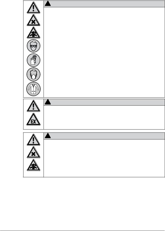
2.4Safety warnings and safety signals used in this manual
DANGER, WARNING, CAUTION and NOTICE are standardized signal words for identifying levels of hazard seriousness of risks related to personal injury and property damage. All signal words, which are related to personal injury are accompanied by the general safety sign.
For your safety it is important to read and fully understand the below table with the different signal words and their definitions!
Sign |
Signal word |
Definition |
Risk level |
|
|
|
|
|
|
|
DANGER |
Indicates a hazardous situation which, if not avoided, will |
|
|
|
result in death or serious injury. |
|||
|
|
|
||
|
|
|
|
|
|
WARNING |
Indicates a hazardous situation which, if not avoided, could |
|
|
|
result in death or serious injury. |
|||
|
|
|
||
|
|
|
|
|
|
CAUTION |
Indicates a hazardous situation which, if not avoided, may |
|
|
|
result in minor or moderate injury. |
|||
|
|
|
||
|
|
|
|
|
no |
NOTICE |
Indicates possible property damage, but no practices |
|
|
related to personal injury. |
(property damage only) |
|||
|
|
|||
|
|
|
||
|
|
|
|
Supplementary safety information symbols may be placed in a rectangular panel on the left to the signal word and the supplementary text (see below example).
!SIGNAL WORD
Space for
supplementary Supplementary text, describing the kind and level of hazard / risk seriousness. safety
information symbols.
8 |
B-90 Operation Manual, Version B |

2 Safety
Table of supplementary safety information symbols
The below reference list incorporates all safety information symbols used in this manual and their meaning.
Symbol Meaning
General warning
Electrical hazard
Explosive gases, explosive environment
Harmful to life-forms
Hot item, hot surface
Device damage
Inhalation of substances
Pressurized gas/air
Ozone formation
Wear protective mask
9 |
B-90 Operation Manual, Version B |

2 Safety
Wear laboratory coat
Wear protective goggles
Wear protective gloves
Heavy weight, lifting requires more than one person
Additional user information
Paragraphs starting with NOTE transport helpful information for working with the device / software or its supplementaries. NOTEs are not related to any kind of hazard or damage (see example below).
NOTE
Useful tips for the easy operation of the instrument / software.
2.5Product safety
Safety warnings in this manual (as described in section 2.4) serve to make the user alert and to avoid hazardous situations emanating from residual dangers by giving appropriate counter measures. However, risks to users, property and the environment can arise when the instrument is damaged, used carelessly or improperly.
2.5.1General hazards
The following safety messages show hazards of general kind which may occur when handling the instrument. The user shall observe all listed counter measures in order to achieve and maintain the lowest possible level of hazard.
Additional warning messages can be found whenever actions and situations described in this manual are related to situational hazards.
10 |
B-90 Operation Manual, Version B |
2 Safety
!Danger
Death by suffocation or serious poisoning by inhalation of inert gases.
•Do not inhale inert gases
•Directly withdraw released gases and gaseous substances by sufficient ventilation
•Only operate the instrument in ventilated environments
•Before operation, check all parts, connections and sealings involved in the gasflow for proper
sealing
•Exchange worn out or defective parts immediately
! |
Danger |
Death or serious poisoning by gases or particles due to O2– sensor or filter malfunction |
|
• Exchange defective O2– sensor immediately |
|
• Exchange O2– sensor regularly within the specified maintenance intervals |
|
• Exchange clogged filters immediately |
|
• Exchange filters regularly within the specified maintenance intervals |
|
• Dispose of filter immediately |
|
!Danger
Death or serious poisoning by inhalation or incorporation of dried particles during spray process.
•Wear safety goggles
•Wear safety gloves
•Wear a suitable protective mask
•Wear a laboratory coat
•Check for proper sealing before use
•Do not inhale dried particles
•Stop drying gas flow before opening the drying circuit
|
|
|
|
|
11 |
|
|
|
B-90 Operation Manual, Version B |
2 Safety
!Danger
Death or serious poisoning by inhalation or incorporation of dried particles at recovery.
•Wear safety goggles
•Wear safety gloves
•Wear a suitable protective mask
•Wear a laboratory coat
•Do not inhale dried particles
•Stop drying gas flow before opening the drying circuit
•Only recover particles in sufficiently ventilated flue or glove-box
•Do not disperse the dried particles
•Do not clean dusty parts with compressed air
!Warning
Death or serious injuries by use in explosive environments.
•Do not operate the instrument in explosive environments
•Do not operate the instrument with explosive gas mixtures
•Before operation, check all gas connections for correct installation
•Directly withdraw released gases and gaseous substances by sufficient ventilation
!Warning
Death or serious poisoning by contact or incorporation of harmful substances at use.
•Before operation, check the instrument for correct assembling
•Before operation, inspect sealings and tubes for good condition
•Exchange worn out or defective parts immediately
•Exchange clogged filters immediately
•Only operate the instrument in ventilated environments
•Directly withdraw released gases and gaseous substances by sufficient ventilation
•Perform a dry-run without sample material and check for gas leakages
12 |
B-90 Operation Manual, Version B |

2 Safety
!Caution
Risk of minor poisoning by inhalation of ozone.
•Directly withdraw released gases and gaseous substances by sufficient ventilation
!Caution
Risk of minor or moderate burnings when handling hot parts.
•Do not touch hot parts
•Let the system cool down for some minutes after use
Notice
Risk of instrument short-circuits and damage by liquids.
•Do not spill liquids over the instrument or its component parts
•Wipe off any liquids instantly
•Place the sample vessel onto the designated reservoir-plate on top of the instrument
•Ensure a safe positioning of the sample vessel
•Do not move the instrument when it is loaded with liquid
•Keep external vibrations away from the instrument
Notice
Risk of instrument damage by internal overpressure.
•External supply pressure must meet the system specifications
•Exchange clogged filters immediately
•Dispose of filter immediately
Notice
Risk of instrument damage by wrong mains supply.
•External mains supply must meet the voltage given on the type plate
•Check for sufficient grounding
13 |
B-90 Operation Manual, Version B |
2 Safety
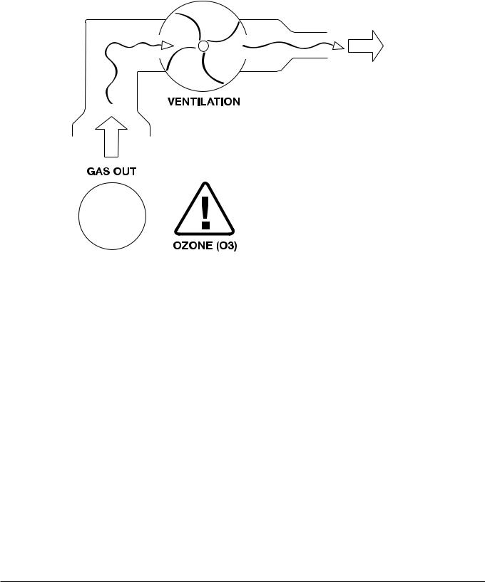
2.5.2Warning labels on housing
The below warning label can be found at the gas outlet connector on the right side of the Nano Spray Dryer B-90.
Meaning
Ozone formation in the electric field of the electrostatic particle collector when using oxygen containing gases as drying gas (like air). Withdraw gases via fume hood or equivalent ventilation system directly.
2.5.3Safety measures
Always wear personal protective equipment such as protective eye goggles, protective clothing, inhalation protection and gloves when working with the instrument.
2.5.4Built-in safety elements and measures
Heating
•Overheating protection circuit.
•Automatic temperature control of heater and inlet temperature.
Spraying
•Automatic spray control.
•Light barrier, to detect the correct placement of the particle collector.
•Overpressure leakage detection.
High voltage and electrostatic charges
•Safety current limitation.
•Internal grounding to arrest electrostatic charges.
Air/Gas
•Automatic processing interruption when system pressure is too low.
•Outlet filter to protect the environment contamination of fine dust particles via exhaust gas tubing.
14 |
B-90 Operation Manual, Version B |

2 Safety
Glass
• High temperature resistance and high transparency borosilicate glass.
Pressure
•Automatic pressure control at outlet filter.
•Over pressure safety valve (opens at 300 mbar).
Optional system configuration with Inert Loop B-295
•Overpressure leakage detection.
•Safe gas condition (< 6 % O2 content) is detected and enables the regulation of the drying gas mixture via a communication cable.
2.6General safety rules
Responsibility of the operator
The head of the laboratory is responsible for training his/her personnel.
The operator shall inform the manufacturer without delay of any safety-related incidents which might occur during operation of the instrument. Legal regulations, such as local, state and federal laws applying to the instrument must be strictly followed.
Duty of maintenance and care
The operator is responsible for the proper condition of instrument at use and that maintenance, service and repair jobs are performed with care and on schedule by authorized personnel only.
Spare parts to be used
Use only genuine consumables and genuine spare parts for maintenance to assure good system performance and reliability. Any modifications to the spare parts used are only allowed with the prior written permission of the manufacturer.
Modifications
Modifications to the instrument are only permitted after prior consultation with and with the written approval of the manufacturer. Modifications and upgrades shall only be carried out by an authorized BUCHI technical engineer. The manufacturer will decline any claim resulting from unauthorized modifications.
15 |
B-90 Operation Manual, Version B |
3 Technical data
3 Technical data
This chapter introduces the reader to the instrument and its specifications. It contains the scope of delivery, technical data, requirements and performance data.
3.1Scope of application and delivery
The Nano Spray Dryer B-90 is available in two different set-ups:
Nano Spray Dryer B-90 Basic
•For aqueous applications with air in ‘open loop’
Nano Spray Dryer B-90 Advanced
•For solvent applications in combination with Inert Loop B-295
•Optional use with Dehumidifier B-296
•Equipped with additional oxygen safety circuit and gas regulation valves
•Accessories are solvent resistant
The scope of delivery can only be checked according to the individual delivery note and the listed order numbers.
NOTE
For additional information about the listed products, see www.buchi.com or contact your local dealer.
3.1.1Standard instrument
Table 3-1: Standard instrument
Product |
Order no. |
|
|
Nano Spray Dryer B-90 Basic |
11055320 |
50 – 60 Hz, 100 – 240 V |
|
|
|
Nano Spray Dryer B-90 Advanced |
11055321 |
50 – 60 Hz, 100 – 240 V |
|
|
|
16 |
B-90 Operation Manual, Version B |

3 Technical data
3.1.2Standard accessories
Table 3-2: Standard accessories
Product |
Order no. |
|
|
Spray head |
051510 |
|
|
Spray head holder |
051508 |
|
|
3 |
Set of 3 spray caps 4.0 µm |
051747 |
|
||
|
Set of 3 spray caps 5.5 µm |
051748 |
|
Set of 3 spray caps 7.0 µm |
051749 |
|
HV–Electrode protected |
11055174 |
|
Protective grid for HV–Electrode |
051680 |
Peristaltic pump complete |
051735 |
|
|
17 |
B-90 Operation Manual, Version B |

3 Technical data
Table 3-2: Standard accessories (cont.)
Product |
Order no. |
|
|
Spray cylinder |
051511 |
Glass cylinder extension |
051549 |
Glass insulation cylinder (no picture) |
051663 |
|
|
1 |
|
Heater complete |
051504 |
|
|
Lifting device |
051607 |
|
|
«Nano Spray Dryer Records» Software |
051776 |
18 |
B-90 Operation Manual, Version B |

Operation Manual
Nano
Spray Dryer B 90
 093261 en
Deckblatt B-90_en.indd 1 |
08.07.2009 09:44:56 |
3 Technical data
Table 3-2: Standard accessories (cont.)
Product |
Order no. |
|
|
Outlet filter |
051656 |
|
|
Operation Manual:
English |
093261 |
|
|
German |
093262 |
|
|
French |
093263 |
|
|
Italian |
093264 |
|
|
Spanish |
093265 |
|
|
3.1.3Standard accessories with the Nano Spray Dryer B-90 Advanced
Table 3-3: Standard accessories with the B-90
Advanced (for ‘closed loop’ operation)
Product |
Order no. |
|
|
Oxygen sensor |
046348 |
|
|
Tygon tubing MH 2075 transparent (per m) |
046314 |
|
|
Tygon tubing F 4040 A yellow (per m) |
046315 |
|
|
Upgrade set Nano Spray Dryer B-90 |
11055748 |
Basic to Advanced |
|
|
|
NOTE
Upgrade set is for organic solvent operation in ‘closed loop’ with the Inert Loop B-295 or Dehumidifier B-296. The upgrade set includes solvent resistant tubing, inert gas regulation valves, oxygen sensor with oxygen analyser. The installation requires support of a BUCHI service engineer.
19 |
B-90 Operation Manual, Version B |

3 Technical data
3.1.4Optional accessories
Table 3-4: Optional accessories
Product |
Order no. |
|
|
Inert Loop B-295, 50 Hz, 200 V |
044779 |
|
|
Inert Loop B-295, 50 Hz, 230 V |
044701 |
|
|
Inert Loop B-295, 60 Hz, 200 V |
046345 |
|
|
Inert Loop B-295, 60 Hz, 230 V |
046344 |
|
|
Upgrade set B–295 for closed cycle |
051783 |
|
|
Dehumidifier B-296, 50/60 Hz, 230 V |
040188 |
|
|
Dehumidifier B–296, 50/60 Hz, 200 V |
040181 |
|
|
Upgrade set B–296 for closed cycle |
051780 |
|
|
Aspirator complete, incl. inlet filter |
051700 |
|
|
20 |
B-90 Operation Manual, Version B |
3 Technical data
Table 3-4: Optional accessories (cont.)
Product |
Order no. |
|
|
Inlet filter |
011235 |
|
|
Air maintenance unit |
004366 |
|
|
Oil-free air compressor, 230V / 50Hz |
027907 |
|
|
Oil-free air compressor, 230V / 60Hz |
11055736 |
|
|
Trolley |
041257 |
|
|
21 |
B-90 Operation Manual, Version B |

3 Technical data
Table 3-4: Optional accessories (cont.)
Product |
Order no. |
|
|
Stand plate |
051775 |
|
|
3.2 |
Technical data |
|
||
|
|
|
|
|
|
|
Table 3-5: Technical data Nano Spray Dryer B-90 |
|
|
|
|
Power consumption |
max. 1500 W |
|
|
|
|
|
|
|
|
Connection voltage |
100–240 VAC ± 10 % |
|
|
|
|
|
|
|
|
Input fuse |
12 A |
|
|
|
|
|
|
|
|
Frequency |
50 / 60 Hz |
|
|
|
|
|
|
|
|
Heating capacity |
max. 1400 W |
|
|
|
|
|
|
|
|
Max. inlet temperature |
120 °C |
|
|
|
|
|
|
|
|
Evaporating capacity |
max. 0.2 l/h H2O |
|
|
|
|
|
(higher rates with organic solvents are possible) |
|
|
|
|
|
|
|
Drying gas flow |
80–160 l/min |
|
|
|
|
|
|
|
|
N2 or CO2 inert gas input pressure |
max. 2 bar |
|
|
|
Spray caps (hole diameters) |
4.0 µm, 5.5 µm, 7.0 µm |
|
|
|
|
|
|
|
|
Mean droplet size range |
8–21 µm |
|
|
|
|
|
|
|
|
Mean particle size range |
300 nm–5 µm |
|
|
|
|
|
|
|
|
Mean residence time |
1–4 sec. |
|
|
|
|
|
|
|
|
Interface |
USB II |
|
|
|
|
|
|
|
|
IP degree of protection (two digits) |
IP 42 |
|
|
|
|
|
Explanation of protection level: |
|
|
|
|
4 Protection provided by the enclosure against access |
|
|
|
|
to hazardous parts (e.g., electrical conductors, |
|
|
|
|
moving parts) and the ingress of solid foreign objects |
|
|
|
|
with a diameter of > 1mm. |
|
|
|
|
2 Protection of the equipment inside the enclosure |
|
|
|
|
against harmful ingress of dripping water when tilted |
|
|
|
|
up to 15°. |
|
|
|
|
|
|
|
Overvoltage category |
II |
|
|
|
|
|
|
|
|
Environmental conditions: |
|
|
|
|
|
Pollution degree |
2 (for indoor use only) |
|
|
|
|
|
|
|
|
Temperature |
5–40 °C |
|
|
|
|
|
|
|
|
Altitude (above sea level) |
up to 2000 m |
|
|
|
|
|
|
|
|
Humidity (curve parameter) |
Maximum relative humidity 80 % up to 31 °C, then |
|
|
|
|
decreasing linearly to 50 % relative humidity at 40 °C |
|
|
|
|
|
22 |
B-90 Operation Manual, Version B |

3 Technical data
Table 3-5: Technical data Nano Spray Dryer B-90 (cont.)
Dimensions (W × H × D) |
|
|
|
Short set-up |
58×110×55 cm |
|
|
|
|
Tall set-up |
58×150×55 cm |
|
|
|
Weight |
|
|
|
Short set-up |
65 kg |
|
|
|
|
Tall set-up |
70 kg |
|
|
|
|
|
|
Table 3-6: Technical data Inert Loop B-295 |
|
|
Power consumption |
max. 1.4 kW |
|
|
|
|
Connection voltage |
200–230 V ± 10 % |
|
|
|
|
Frequency |
50/60 Hz |
|
|
|
|
Min. outlet temperature |
down to -25 °C |
|
|
|
|
Rate of cooling |
800 W at -10 °C |
|
|
|
|
Dimensions (W×H×D) |
60×70×84.5 cm |
|
|
|
|
Weight |
95 kg |
|
|
|
|
|
|
|
Table 3-7: Technical data Dehumidifier B-296 |
|
|
Power consumption |
700 W |
|
|
|
|
Connection voltage |
200/230 V ± 10 % |
|
|
|
|
Frequency |
50/60 Hz |
|
|
|
|
Min. outlet temperature |
+ 2 °C |
|
|
|
|
Rate of cooling |
600 W at 0 °C |
|
|
|
|
Dimensions (W×H×D) |
35×40×60 cm |
|
|
|
|
Weight |
36 kg |
|
|
|
|
|
|
|
Table 3-8: Technical data Aspirator |
|
|
Power consumption |
max. 1000 W |
|
|
|
|
Connection voltage |
200–240 V ± 10 % |
|
|
|
|
Input fuse |
FST 5×20 T8A L 250 V |
|
|
|
|
Frequency |
50/60 Hz |
|
|
|
|
Dimensions (W×H×D) |
47,5×30×32 cm |
|
|
|
|
Weight |
20 kg |
|
|
|
|
IP degree of protection (two digits) |
IP 20 |
|
|
|
Explanation of protection level: |
|
|
2 Protection provided by the enclosure against access |
|
|
to hazardous parts (e.g., electrical conductors, |
|
|
moving parts) and the ingress of solid objects up to |
|
|
12 mm, e.g. persons fingers. |
|
|
0 No protection against ingress of liquids. |
|
|
|
23 |
B-90 Operation Manual, Version B |

3 Technical data
3.3 |
Materials used |
|
|
|
|
|
|
|
|
Table 3-9: Materials used |
|
|
|
Component |
Material designation |
|
|
|
|
|
|
Glass assembly |
3.3 borosilicate glass |
|
|
|
|
|
|
Heater |
Aluminum and stainless steel |
|
|
|
|
|
|
Spray head |
Stainless steel |
|
|
|
|
|
|
Spray cap membrane |
Stainless steel |
|
|
|
|
|
|
Spray cap o-ring |
EPDM75 |
|
|
|
|
|
|
Feeding tubes |
Silicone and tygon |
|
|
|
|
|
|
Tube connector at feeding tube |
PEEK |
|
|
|
|
|
|
Particle collecting tube |
Stainless steel polished |
|
|
|
|
|
|
HV–electrode |
Stainless steel |
|
|
|
|
|
|
Sealings for spray and glass cylinder |
Silicone |
|
|
|
|
24 |
B-90 Operation Manual, Version B |

4 Description of function
4 Description of function
This chapter explains the basic working principle of the Nano Spray Dryer B-90 Basic (‘open loop’ only) and the Nano Spray Dryer B-90 Advanced (equipped with O2-sensor and inert gas regulation valves for ‘closed loop’ mode). It also shows how the instruments are structured and provides a general functional description of their assemblies.
4.1Functional principle
The Nano Spray Dryer B-90 models have been designed to produce particles out of a solution or suspension with a particle size between 0,3 µm–5 µm by drying or encapsulation at a yield rate of up to 90 %. The output particle size depends mainly upon the chosen spray cap. The Nano Spray Dryer B-90 also allows processing of nano particles (<100 nm) in nanosuspensions or emulsions e.g. for encapsulation. The drying gas flow and the product stream are described below.
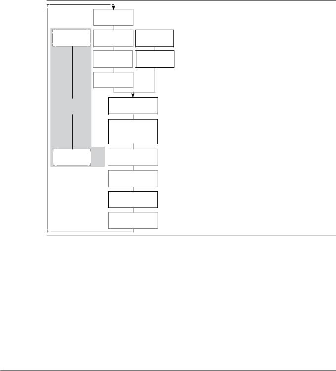
4.1.1Drying gas circuit
The sprayed liquid is accompanied by a co-current gas flow. For highest yields, a controlled gas flow at a sufficient quality and a defined temperature is required. To ensure this, a flow regulator and heating loop has been implemented
|
a |
|
|
|
Drying gas inlet |
|
|
Gas regulator |
b |
Feed pump |
|
Flow meter |
|||
|
|
||
|
c |
Spray head |
|
|
Electrical heater |
||
|
|
||
|
d |
|
|
|
Inlet temp. sensor |
|
|
f |
Drying cylinder |
||
safety loop |
|
|
|
|
Electrical particle |
||
|
collector |
|
|
Oxygen sensor |
e |
|
|
Rel. pressure sensor |
|||
|
|||
|
g |
|
|
|
Outlet temp. sensor |
||
|
h |
|
|
|
Outlet filter |
||
|
i |
|
|
|
Drying gas outlet |
||
aThe drying and transport gas enters the instrument via the “Drying gas inlet”.
bThe gas flow is monitored by a “Flow meter” which influences the “Gas regulator”.
cSubsequently the “Electrical heater” heats up the gas to the desired drying temperature.
dVia the “Inlet temperatur sensor” the heater is regulated to achieve the desired gas temperature.
eThe “Relative pressure sensor” compares the internal to the environmental pressure. In the event of a massive pressure loss (e.g. a leakage) this sensor stops the drying process.
fIn ‘closed loop’ mode, as part of the safety loop the “Oxygen sensor” supervises the percentage of oxygen in the drying gas. In emergency, it stops the process.
gThe “Outlet temperature sensor” is located after the particle collector. The temperature drop between inlet and outlet temperature sensor is measured as a process value.
hThe “Outlet filter” is a safety relevant item. It retains possibly harmful particles towards the environment in ‘open loop’. In ‘closed loop’ the outlet filter is an essential part for cleaning the recycled gas from unwanted residues and impurities.
i The “Drying gas outlet” works as an exhaust.
25 |
B-90 Operation Manual, Version B |
4 Description of function
Optional drying gas recycling in ‘closed loop’ mode:
In ‘closed loop’ mode of the Nano Spray Dryer B-90 Advanced the “Drying gas outlet” i is connected via the Inert Loop B-295 or Dehumidifier B-296 and Aspirator to the “Drying gas inlet” a.
4.1.2Spray drying process overview
The drying process takes place inside the drying cylinder. A drying gas flow is established and tiny droplets of sample material are injected by the spray head. The sample material is dried by the hot gas. Because of the tiny particle size, an electrical field of sufficient power is needed to retrieve the particulate material from the drying gas flow. The following scheme informs about the different processing stages in general.
|
Drying gas inlet |
|
|
Gas regulator |
Flow meter |
a |
|
Feed pump |
|||
|
|
||
|
Electrical heater |
b |
|
|
Spray head |
||
|
|
||
|
Inlet temp. sensor |
|
|
safety loop |
c |
|
|
Drying cylinder |
|||
|
|||
|
d |
|
|
|
Electrical particle |
||
|
collector |
|
|
 Oxygen sensor
  Rel. pressure sensor
Outlet temp. sensor
e
Outlet filter
aThe “Feed pump” constantly feeds the “Spray head” with liquid sample material.
bThe “Spray head” produces finest droplets and injects them into the “Drying cylinder”.
cThe heated drying gas enters laminar from the top into the “Drying cylinder”. Consequently, the injected drops of sample material are gently dried to solid particles.
dThe “Electrical particle collector” retrieves the dried solid particles by an electrostatic field.
eThe exhaust gas leaves the spray dryer via the “Outlet filter” which retains free particles from the gas.
Drying gas outlet
26 |
B-90 Operation Manual, Version B |

4 Description of function
Processing inside the drying cylinder
The following draft offers a more detailed view about the basic spray drying process. The drying gas (a) passes the heater (b) and the vertically or angular aligned spray head (e). The injected micro doplets of the sample material are dried while beeing vortexed in the gas flow inside the spray cylinder (f). An electric field is generated by high voltage between the collecting electrode (h) and
the HV-electrode (i). While the HV-electrode deflects the particulate material, the collecting electrode attracts them. Thus, particles are depositing at the inside of the collecting electrode (g).
c |
|
b |
|
|
|
|
|
|
d |
||
|
|
|
e |
|
|
|
|
|
|
|
|
|
|
|
|
|
|
|
f |
|
|
|
|
g |
|
|
|
|
|
|
|
|
|
|
|
|
|
h |
j |
|
l |
|
|
||
|
|
||
|
i |
|
|
|
k |
|
|
aDrying gas inlet (optional with inlet filter and Aspirator)
b Electrical heater
c Inlet temperature sensor d Display/Control
e Spray head (angular or vertical installation) f Spray cylinder and drying section
g Finished product at particle collecting electrode h Particle collecting electrode
i HV–electrode
j Outlet temperature sensor k Outlet filter
lDrying gas outlet (in ‘closed loop’ connected to Inert Loop B-295 and Aspirator)
4.2Spray generation
The Nano Spray Dryer B-90 uses piezotechnology to generate precisely controlled micro droplets from bulk liquids without the use of propellants.
push push
pull |
pull |
The spray head includes a piezoelectric actuator with a thin stainless steel membrane. The membrane has an array of micron-sized holes (spray meshes of 4.0, 5.5 or 7.0 µm hole size) and vibrates at ultrasonic frequency (60 kHz). Because of these vibrations
the membrane eject precisely sized droplets at high speed.
NOTE
The smaller the mesh size, the smaller the ejected droplets and dried particles. Since the vibrations frequency is fixed, a smaller mesh size will have less throughput per time.
4.3Heating system
The compact heater module provides optimal energy input to heat the drying gas up to 120 °C. The heating system consists of an electrically heated porous metal foam to minimize the heat–up time and to generate a laminar gas flow towards the drying section. The heating control is based on a pluggable PT–1000 temperature sensor.
27 |
B-90 Operation Manual, Version B |
4 Description of function
4.4Drying air generation
In ‘open loop’ mode the required drying air can be either supplied by an in-house compressed air supply, an oil-free compressor or a BUCHI Aspirator (see section 3.1.4, Optional accessories).
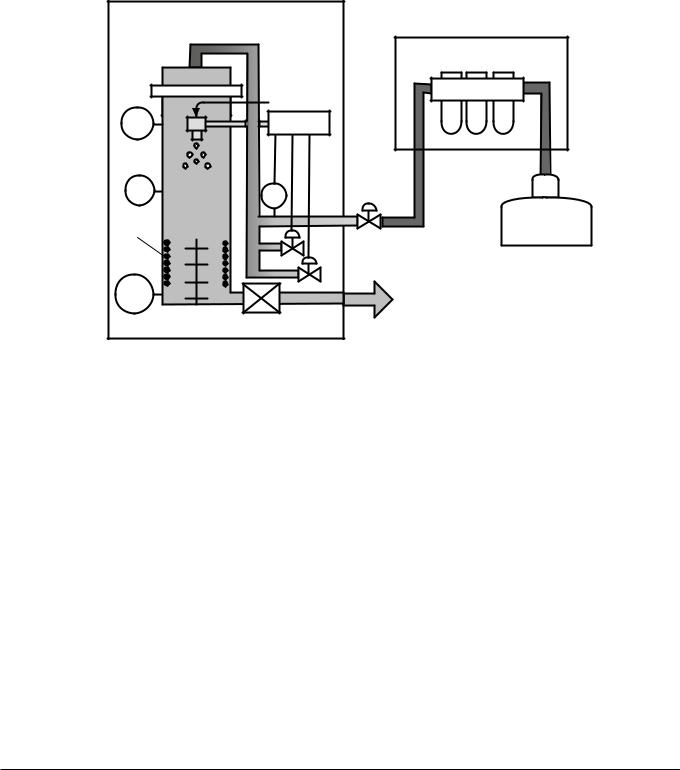
4.4.1Compressed air supply
In ‘open loop’ configuration, compressed air is used as standard drying gas. The air maintenance unit (order no. 004366) is additionally recommended to assure gas of clean, dry and oil free quality. A pressure regulating valve is required to match the instruments input pressure value.
Nano Spray Dryer B-90 |
|
|
|
Basic |
Air maintenance unit |
|
|
|
|
Feed |
b (optional) |
|
|
|
TIN |
Control |
|
P |
FI |
c |
Compressed |
|
|
|
|
||
Product |
|
|
a |
|
|
|
air |
||
TOUT |
|
Exhaust gas |
|
|
|
|
|
|
|
|
Outlet filter |
|
|
|
a Compressed air source
b Optional air maintenance unit
cPressure regulating valve
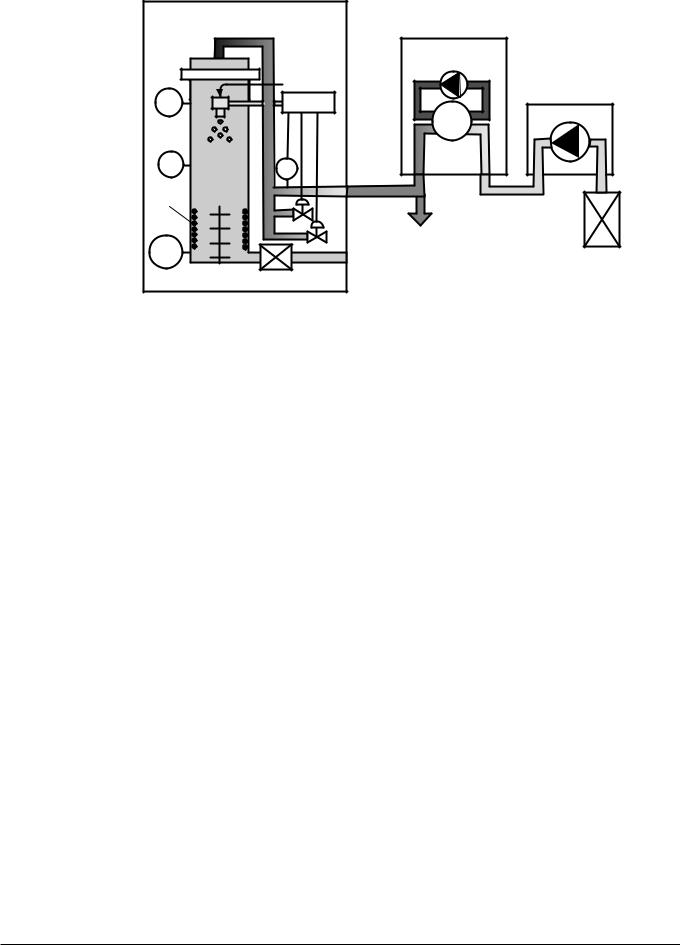
4.4.2Aspirator in blowing mode
If there is no compressed air available in the laboratory, the BUCHI Aspirator unit with inlet filter (order no. 051700) can be used to establish the required drying air flow rate. The Aspirator can be connected directly to the inlet of the Nano Spray Dryer B-90 without a pressure regulating valve. In case of higher ambient humidity use the Dehumidifier B-296 to achieve dry air.
NOTE
If the humidity of the air is too high, the current in the particle collector could be too low.
Air inlet filter
The air inlet filter is required to avoid any contamination of the instruments by fine particles in the lab environment. It is to be connected to the inlet of the Aspirator, so the instrument aspirates filtered ambient air. The filter consists of a stainless steel grid for outer protection and an ultra filter based on a glass fibre textile (filter class S according to DIN 24184).
28 |
B-90 Operation Manual, Version B |
4 Description of function
Nano Spray Dryer B-90
Basic
|
Feed |
TIN |
Control |
P |
FI |
Product |
|
TOUT
Outlet filter
Dehumidifier |
c (optional) |
B-296 |
|
TCOOL |
Aspirator |
|
b
Condensate |
a |
|
 Exhaust gas Inlet filter
a Inlet filter to filter out dust and particles b Aspirator as air supply source
c Optional Dehumidifier B-296
NOTE
The Aspirator is also used with a Nano Spray Dryer with the Inert Loop B-295 or Dehumidifier B-296 to
B-90 Advanced in ‘closed loop’ configuration recirculate the inert gas (N2 or CO2).
4.5Sample feed circulation with peristaltic pump
The peristaltic pump circulates the sample feed between the product vessel and the spray head. It assures a constant substance feeding for the spray generation.
NOTE
Dry run of the pump and the spray head does not damage the instrument or parts of it in the medium term.
4.6Particle collector
Solid particles are accumulated at the wall of the cylindrical particle collecting electrode by a strong electrical field. The electrical field is generated via high voltage.
4.7Outlet filter
The outlet filter (order no. 051656) prevents environmental pollution by particles. It is installed inside the housing of the Nano Spray Dryer B-90. See section 5.5.1 for information about access and exchange.
29 |
B-90 Operation Manual, Version B |
4 Description of function
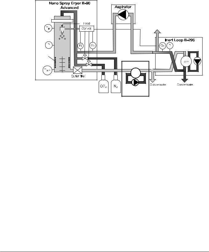
4.8Inert Loop B-295
The Inert Loop B-295 is an accessory to enable the safe spray drying of organic solvents in a ‘closed loop’ configuration. It comprises a cooling unit with pressure and oxygen monitoring elements and safety controls. Communication to the Nano Spray Dryer B-90 Advanced is established via a communication cable.
Product |
a
Exhaust gas
TCOOL |
Dehumidifier |
|
B-296 c |
b |
a Exhaust gas to fume hood or glove box ventilation |
c Condensation and cooling unit |
outlet |
|
b Solvent condensate |
|
Functional principle:
•The inert drying gas (N2 or CO2) is loaded with solvent from the spray drying process.
•The loaded gas enters the Inert Loop B-295 and is cooled down in its internal preheat exchanger.
•The solvent is condensed in the refrigerator and collected in a closed bottle.
•Subsequently, the cleaned and cooled gas stream is heated up in the preheat exchanger and flows back through an Aspirator to the Nano Spray Dryer B-90 Advanced.
Dehumidifier B-296
If mixtures of organic solvents and water are used in ‘closed loop’ configuration, BUCHI strongly recommends to install the additional Dehumidifier B-296. The Dehumidifier B-296 is condensing the water to prevent water from entering the Inert Loop B-295. This is necessary to protect the heat exchanger in the refrigerator from water freezing and potential damage.
30 |
B-90 Operation Manual, Version B |
 Loading...