


Operation Manual
Rotavapor® R-220 SE
11593356 en

Table of contents
Table of contents
1 |
About this manual . . . . . . . . . . . . . . . . . . . . . . . . . . . . . . . . . . . . . |
. |
. 7 |
|
2 |
Safety . . . . . . . . . . . . . . . . . . . . . . . . . . . . . . . . . . . . . . . . . . . . |
. |
. 8 |
|
|
2.1 |
User qualification . . . . . . . . . . . . . . . . . . . . . . . |
. |
8 |
|
2.2 |
Proper use . . . . . . . . . . . . . . . . . . . . . . . . . |
. |
8 |
|
2.3 |
Improper use . . . . . . . . . . . . . . . . . . . . . . . . |
. |
8 |
|
2.4 |
Safety warnings and safety signals used in this manual . . . . . . . . . . |
. |
9 |
|
2.5 |
Product safety |
|
12 |
|
2.5.1 |
General hazards |
|
12 |
|
2.5.2 |
Warning labels on housing . . . . . . . . . . . . . . . . . . . . |
|
13 |
|
2.5.3 |
Personal safety measures |
|
14 |
|
2.5.4 |
Built-in safety elements and measures . . . . . . . . . . . . . . . . |
|
14 |
|
2.6 |
General safety rules . . . . . . . . . . . . . . . . . . . . . . |
. |
15 |
3 |
Technical data . . . . . . . . . . . . . . . . . . . . . . . . . . . . . |
. |
.16. . . . |
|
|
3.1 |
Available system configurations and dimensions . . . . . . . . . . . . |
. |
16 |
|
3.1.1 |
Application areas . . . . . . . . . . . . . . . . . . . . . . . |
. 17 |
|
|
3.1.2 |
Typical example applications and accessories |
|
17 |
|
3.2 |
Technical data |
|
18 |
|
3.3 |
Materials used |
|
20 |
4 |
Description of function . . . . . . . . . . . . . . . . . . . . . . . . . . |
|
. 21. . . . . |
|
|
4.1 |
Functional principle of a Rotavapor evaporation |
|
21 |
|
4.2 |
Rotavapor front-side . . . . . . . . . . . . . . . . . . . . . . |
|
23 |
|
4.3 |
Tubing scheme . . . . . . . . . . . . . . . . . . . . . . . . |
|
24 |
|
4.3.1 |
Cooling water routing . . . . . . . . . . . . . . . . . . . . . . |
|
26 |
|
4.3.2 |
Vaccum routing . . . . . . . . . . . . . . . . . . . . . . . . |
|
27 |
|
4.4 |
User interface front-side |
|
29 |
|
4.5 |
Connection field at the rear-side |
|
30 |
5 |
Putting into operation . . . . . . . . . . . . . . . . . . . . . . . . . . . . . . . . . . . |
. |
33 |
|
|
5.1 |
Installation site |
|
33 |
|
5.2 |
Electrical connections |
|
34 |
|
5.3 |
Sensor setup and adjustments . . . . . . . . . . . . . . . . . . |
. |
35 |
|
5.3.1 |
Level sensors . . . . . . . . . . . . . . . . . . . . . . . . |
. |
36 |
|
5.3.2 |
Cooling water flow sensor |
|
37 |
|
5.3.3 |
Foam sensor . . . . . . . . . . . . . . . . . . . . . . . . |
. |
38 |
|
5.3.4 |
Vapor temperature sensor |
|
40 |
|
5.3.5 |
Cooling water temperature sensor |
|
41 |
|
5.4 |
Battery driven lift function at power failure |
|
41 |
|
5.5 |
Setting up the support rod(s) . . . . . . . . . . . . . . . . . . . |
. 42 |
|
|
5.6 |
Condenser clamps . . . . . . . . . . . . . . . . . . . . . . |
. |
43 |
|
5.7 |
EasyClamps |
|
44 |
|
5.8 |
Inlet valve . . . . . . . . . . . . . . . . . . . . . . . . . . |
|
45 |
|
5.9 |
Glassware and configurations |
|
46 |
5.10Additional cleaning measures for food, pharma and cosmetic applications . . . . 46
5.10.1 |
Primary cleaning |
46 |
5.10.2 |
Example for a disinfection via an evaporation cycle . . . . . . . . . . . . |
47 |
5.11 |
Verification of the disinfection process |
47 |
5.11.1 |
Controlled contamination and distillation |
48 |
3 |
R-220 SE Operation Manual, Version F |

Table of contents
5.11.2 |
Disinfection . . . . . . . . . . . . . . |
. . . . . . |
. . . . |
. |
. 48 |
5.11.3 |
Sampling for determination of the germ count |
|
|
|
48 |
5.11.4 |
Final cleaning and drying . . . . . . . . . |
. . . . . . |
. . . . . |
. |
48 |
5.12 |
General installation instructions for glassware . . |
. . . . . . |
. . . . . |
. |
49 |
5.13 |
Single receiver |
|
|
|
51 |
5.14 |
Heating bath filling level . . . . . . . . . . |
. . . . . . |
. . . . |
. |
. 55 |
5.15Heating bath setup for 2×1800 W heating element . . . . . . . . . . . . 56
|
5.15.1 |
Water as heating transfer medium |
|
58 |
|
5.15.2 |
Heating transfer media with high boiling point . . . . . . . . . . . . . . . . . . |
. . . |
59 |
|
5.16 |
Heating bath setup for 4.2 and 6.3 kW heating element |
|
60 |
|
5.17 |
Attaching and removing evaporating flasks . . . . . . . . . . . . . |
. . |
62 |
|
5.18 |
Adjusting the snap flange . . . . . . . . . . . . . . . . . . . |
. . |
64 |
|
5.19 |
Installation and usage of a shut-off tap . . . . . . . . . . . . . . |
. . |
65 |
|
5.20 |
Vacuum controller installation / removal . . . . . . . . . . . . . . |
. . |
66 |
|
5.21 |
Controller upgrade . . . . . . . . . . . . . . . . . . . . . |
. . |
67 |
|
5.22 |
Final installation check |
|
67 |
6 |
Operation . . . . . . . . . . . . . . . . . . . . . . . . . . . . . |
. . |
. 68. . . . . |
|
|
6.1 |
Evaporation in three steps |
|
68 |
|
6.2 |
Optimal distillation conditions . . . . . . . . . . . . . . . . . . |
. |
. 69 |
|
6.3 |
Solvent table . . . . . . . . . . . . . . . . . . . . . . . |
. . |
70 |
7 |
Maintenance and repairs . . . . . . . . . . . . . . . . . . . . . . . |
. . |
. 71. . . . . |
|
|
7.1 |
Customer service . . . . . . . . . . . . . . . . . . . . . . |
. |
. 71 |
|
7.2 |
Regular service and checks . . . . . . . . . . . . . . . . . . |
. . |
72 |
|
7.2.1 |
System tightness . . . . . . . . . . . . . . . . . . . . . . |
. |
. 72 |
|
7.2.2 |
Sealings and hoses . . . . . . . . . . . . . . . . . . . . . |
. . |
72 |
|
7.2.3 |
Glassware and clamps . . . . . . . . . . . . . . . . . . . . |
. |
. 72 |
|
7.2.4 |
Housing, heating bath, cables and accessories . . . . . . . . . . . . |
. |
. 72 |
|
7.3 |
Snap flange coupling, flask seal and vapor duct |
|
74 |
|
7.4 |
Distribution head seal and vacuum seal . . . . . . . . . . . . . . |
. . |
77 |
8 |
Troubleshooting . . . . . . . . . . . . . . . . . . . . . . . . . . . |
. . |
. 79. . . . . |
|
|
8.1 |
Resetting the over-temperature protection |
|
79 |
|
8.2 |
Error messages and their remedy . . . . . . . . . . . . . . . . |
. . |
80 |
|
8.3 |
Resettable automatic system fuses . . . . . . . . . . . . . . . . |
. |
. 84 |
9 |
Shutdown, storage, transport and disposal . . . . . . . . . . . . . . . . . . . . . |
. . . |
85 |
|
|
9.1 |
Storage and transport |
|
85 |
|
9.2 |
Disposal |
|
86 |
|
9.2.1 |
Lead-acid battery . . . . . . . . . . . . . . . . . . . . . . |
. |
. 86 |
10 |
Spare |
parts . . . . . . . . . . . . . . . . . . . . . . . . . . . . . . . . . . . . . . . |
. . . |
88 |
|
10.1 |
Reflux glass configurations . . . . . . . . . . . . . . . . . . |
. . |
89 |
|
10.1.1 |
'R' configuration |
|
90 |
|
10.1.2 |
'RB' configuration |
|
91 |
|
10.1.3 |
'C' configuration |
|
92 |
|
10.1.4 |
'BASIC' configuration . . . . . . . . . . . . . . . . . . . . |
. . |
93 |
|
10.2 |
Decending glass configurations . . . . . . . . . . . . . . . . . |
. . |
94 |
|
10.2.1 |
'D' configuration |
|
95 |
|
10.2.2 |
'D2 HP' configuration . . . . . . . . . . . . . . . . . . . . |
. . |
96 |
|
10.2.3 |
'D2' configuration . . . . . . . . . . . . . . . . . . . . . . |
. |
. 97 |
|
10.2.4 |
'DB' configuration |
|
98 |
|
10.2.5 |
'DB2' configuration . . . . . . . . . . . . . . . . . . . . . |
. . |
99 |
|
10.3 |
Receiving vessel parts |
|
100 |
4 |
R-220 SE Operation Manual, Version F |

Table of contents
10.5 |
Optional equipment and upgrade parts . . . . . |
. . . . . . |
. . . . |
|
. 105 |
11 Declarations and requirements . . . . . . . . . . . . . . . . . . . . . . . . . . . . . . |
.106 |
||||
11.1 |
FCC requirements (for USA and Canada) . . . . |
. . . . . . |
. . . . |
. |
106 |
11.2 |
Declaration of conformity . . . . . . . . . . |
. . . . . . |
. . . . |
|
.107 |
5 |
R-220 SE Operation Manual, Version F |

1 About this manual
1 About this manual
This manual describes the Rotavapor R-220 SE and provides all information required for its safe operation and to maintain it in good working order.
It is addressed to laboratory personnel and operators in particular.
Read this manual carefully before installing and running your system and note the safety precautions in chapter 2 in particular. Store the manual in the immediate vicinity of the instrument, so that it can be consulted at any time.
No technical modifications may be made to the instrument without the prior written agreement of BUCHI. Unauthorized modifications may affect the system safety or result in accidents. Technical data are subject to change without notice.
NOTE
The symbols pertaining to safety (WARNINGS and ATTENTIONS) are explained in chapter 2.
This manual is copyright. Information from it may not be reproduced, distributed or used for competitive purposes, nor made available to third parties. The manufacture of any component with the aid of this manual without prior written agreement is also prohibited.
The following product names and any registered and unregistered trademarks mentioned in this manual are used for identification purposes only and remain the exclusive property of their respective owners:
• Rotavapor® is a registered trademark of BÜCHI Labortechnik AG
The English manual is the original language version and serves as basis for all translations into other languages. If you need another language version of this manual, you can download available versions at www.buchi.com.
7 |
R-220 SE Operation Manual, Version F |

2 Safety
2 Safety
This chapter highlights out the safety concept of the instrument and contains general rules of behavior and warnings from direct and indirect hazards concerning the use of the product. For the users' safety, all safety instructions and safety messages in the individual chapters shall
be strictly observed and followed. Therefore, the manual must always be available to all persons performing the tasks described herein.
2..1 User qualification
The instrument may only be used by laboratory personnel and other persons who on account of training and professional experience know of the potential dangers that can develop when operating the instrument.
Untrained personnel, or persons who are currently being trained, require careful supervision by a qualified person. The present Operation Manual serves as a basis for training.
2..2 Proper use
The rotary evaporator has been designed for use in technical laboratories and in production. It is authorized for use in applications that work with the evaporation and condensation of solvents.
•Evaporation of solvents and suspensions
•Synthesis and cleaning of refined chemicals
•Reactions under reflux
•Recycling and concentration of solvents
•Re-crystallization
•Drying of powders and granulates
2..3 Improper use
Applications not mentioned in section 2.2 are considered to be improper. Applications which do not comply with the technical data (see section 3 of this manual) are also considered to be improper.
The operator bears the sole risk for any damages or hazards caused by improper use!
The following uses are expressly forbidden:
•Use of the instrument in explosive environments
•The production and processing of materials that can cause spontaneous reactions (e.g. explosives; metal hydrids or solvents that can form peroxides)
•Processing with explosive gas mixtures
•Working without the evaporating flask being immersed in the water bath (risk of breakage)
•The drying of hard, brittle materials (e.g., stones, soil samples) that might cause damage to the receiving flask
•Shock-cooling of the evaporating flask and other glass parts
•Installation or use of the instrument in rooms, which require ex-protected instruments
•For safety reasons, only original spare parts must be used
•Using the flask handler installed on the heating bath to lift or lower an evaporating flask
8 |
R-220 SE Operation Manual, Version F |
2 Safety
2..4 Safety warnings and safety signals used in this manual
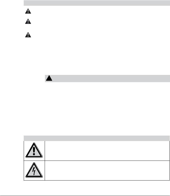
DANGER, WARNING, CAUTION and NOTICE are standardized signal words for identifying levels of hazard seriousness of risks related to personal injury and property damage. All signal words, which are related to personal injury are accompanied by the general safety sign.
For your safety it is important to read and fully understand the below table with the different signal words and their definitions!
Sign |
Signal word |
Definition |
Risk level |
|
|
|
|
|
|
|
DANGER |
Indicates a hazardous situation which, if not avoided, will result in |
|
|
|
death or serious injury. |
|||
|
|
|
||
|
|
|
|
|
|
WARNING |
Indicates a hazardous situation which, if not avoided, could result |
|
|
|
in death or serious injury. |
|||
|
|
|
||
|
|
|
|
|
|
CAUTION |
Indicates a hazardous situation which, if not avoided, may result |
|
|
|
in minor or moderate injury. |
|||
|
|
|
||
|
|
|
|
|
no |
NOTICE |
Indicates possible property damage, but no |
|
|
practices related to personal injury. |
(property damage only) |
|||
|
|
|||
|
|
|
||
|
|
|
|
Supplementary safety information symbols may be placed in a rectangular panel on the left to the signal word and the supplementary text (see below example).
Space for |
! |
SIGNAL WORD |
|
|
|
||
Supplementary text, describing the kind and level of hazard / risk seriousness. |
|||
supplementary |
|||
safety |
• List of measures to avoid the herein described hazard or hazardous situation. |
||
information |
• ... |
|
|
symbols. |
• ... |
|
|
|
|
|
|
Table of supplementary safety information symbols
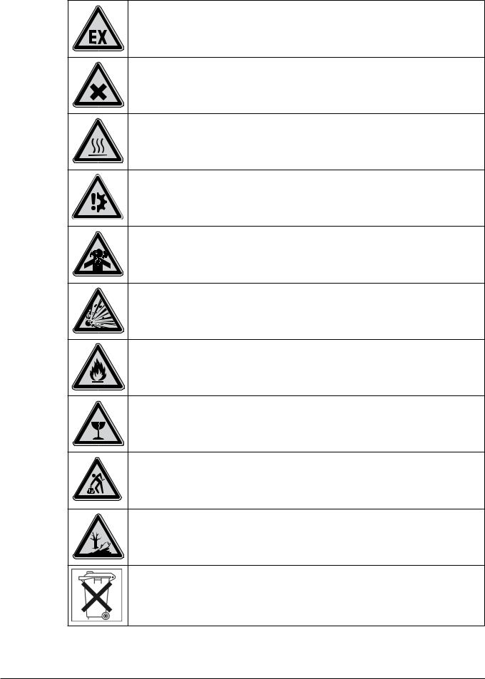
The below reference list incorporates all safety information symbols used in this manual and their meaning.
Symbol Meaning
General warning
Electrical hazard
9 |
R-220 SE Operation Manual, Version F |
2 Safety
Explosive gases, explosive environment
Harmful to life-forms
Hot item, hot surface
Device damage
Inhalation of substances
Explosive substances
Flammable substances
Fragile items / content
Warning, heavy item
Environmental pollution hazard
Do not dispose of in household trash
10 |
R-220 SE Operation Manual, Version F |
2 Safety
Use of water is mandatory (non-standard symbol)
Wear protective mask
Wear laboratory coat
Wear protective goggles
Wear protective gloves
Heavy weight, lifting requires more than one person
Additional user information
Paragraphs starting with NOTE transport helpful information for working with the device / software or its supplementaries. NOTEs are not related to any kind of hazard or damage (see example below).
NOTE
Useful tips for the easy operation of the instrument / software.
11 |
R-220 SE Operation Manual, Version F |
2 Safety
2..5 Product safety
Safety warnings in this manual (as described in section 2.4) serve to make the user alert and to avoid hazardous situations emanating from residual dangers by giving appropriate counter measures. However, risks to users, property and the environment can arise when the instrument is damaged, used carelessly or improperly.
2..5..1 General hazards
The following safety messages show hazards of general kind which may occur when handling the instrument. The user shall observe all listed counter measures in order to achieve and maintain the lowest possible level of hazard.
Additional warning messages can be found whenever actions and situations described in this manual are related to situational hazards.
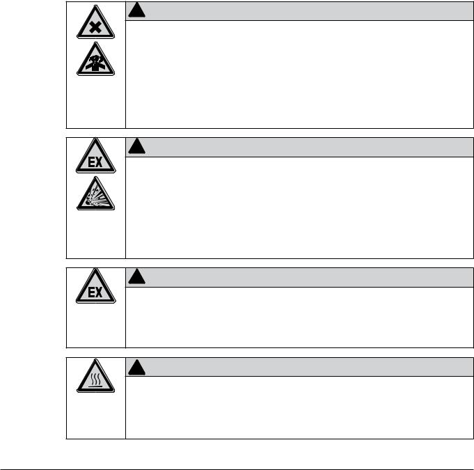
! WARNING
Death or serious poisoning by inhalation of hazardous heating bath liquids.
•Do not inhale fumes from the heating bath
• Keep the heating bath temperature as low as reasonably practicable
• Obtain the material safety data sheets of all used liquids
•Wear appropriate personal protective equipment
•Do not use liquids of unknown composition
•Directly withdraw released fumes and gaseous substances by sufficient ventilation
•Only operate the instrument in ventilated environments
! WARNING
Death or serious injuries by formation of explosive atmospheres inside the instrument.
•Directly withdraw released fumes and gaseous substances by sufficient ventilation at filling
•Before operation, check all gas connections for correct installation
•Establish inert system atmosphere before processing substances that can form explosive or reactive gases or powders
•Check for proper earth connection to lead off electrostatic charges
! WARNING
Death or serious injuries by use in explosive environments.
•Do not operate the instrument in explosive environments
•Do not operate the instrument with explosive gas mixtures
•Directly withdraw released gases and gaseous substances by sufficient ventilation
! CAUTION
Risk of minor or moderate burns when handling hot parts.
•Do not touch hot parts or surfaces
•Drive down the heating bath after distillation
•Let the evaporating flask cool down for some minutes after use
12 |
R-220 SE Operation Manual, Version F |

2 Safety
NOTICE
Risk of instrument short-circuits and damage by liquids.
•Do not spill liquids over the instrument or its component parts
•Wipe off any liquids instantly
•Ensure a safe positioning of the evaporating flask for storage
•Do not move the instrument when it is loaded with liquid
•Keep external vibrations away from the instrument
NOTICE
Risk of instrument damage by internal overpressure.
•External supply pressure must meet the system specifications
•Exchange clogged filters immediately
•Dispose of filter immediately
NOTICE
Risk of instrument damage by wrong mains supply.
•External mains supply must meet the voltage given on the type plate
•Check for sufficient grounding
NOTICE
Risk of glass breakage by excessive strains.
•Mount all glassware parts without strains
•Check glassware for proper fixing regularly and readjust fixing points if necessary
• Do not use defective glassware
2..5..2 Warning labels on housing
The following warning sticker(s) can be found on the housing or assemblies of the Rotavapor:
Symbol |
Meaning |
Location |
|
|
|
|
Hot item, hot surface |
Sticker is located on top of the housing and at |
|
the racks |
|
|
|
|
|
|
|
|
Fill in H2O as heating medium only! |
Sticker is located on top of the heating |
|
distributor box at the heating bath |
|
|
|
|
|
|
|
13 |
R-220 SE Operation Manual, Version F |
2 Safety
2..5..3 Personal safety measures
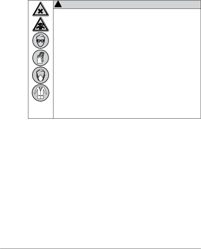
Always wear personal protective equipment such as protective eye goggles, protective clothing and gloves when working with the instrument. Wear inhalation protection when working with hazardous solvents and all kind of respirable material or material of unknown composition.
! WARNING
Death or serious poisoning by contact or incorporation of harmful media at use.
•Before operation, inspect seals, tubes and hoses for good condition
• Exchange worn out or defective parts immediately
• Before operation, check the instrument for correct assembly and proper seal
•Only operate the instrument in ventilated environments
•Directly withdraw released gases and gaseous substances by sufficient ventilation
•Wear safety goggles
•Wear safety gloves
•Wear a suitable protective mask
•Wear a laboratory coat
•Obtain all additional requirements listed in the supplementary data sheets of the media in use
2..5..4 Built-in safety elements and measures
Heating bath
•Overheating protection circuit
•Selectable max. temperature setpoint of the heating bath
•Dry-run protection against unsufficient heating liquid level
•Automatic temperature control of heater
•Automatic heating bath lowering via built-in, rechargeable battery in certain error situations
Electrostatic charges
• Internal grounding to lead-off electrostatic charges
Air / gas
•Automatic pressure relief when system pressure exceeds system specifications
•Automatic aeration in case of power interruption
Glass
•High temperature resistance and high transparency borosilicate glass
•Plastic+Glas coating as effective splinter protection in the event of an implosion (except evaporating flask)
14 |
R-220 SE Operation Manual, Version F |

2 Safety
2..6 General safety rules
Responsibility of the operator
The head of the laboratory is responsible for training his/her personnel.
The operator shall inform the manufacturer without delay of any safety-related incidents which might occur during operation of the instrument. Legal regulations, such as local, state and federal laws applying to the instrument must be strictly followed.
Duty of maintenance and care
The operator is responsible for the proper condition of the instrument at use and that maintenance, service and repair jobs are performed with care and on schedule by authorized personnel only.
Spare parts to be used
Use only genuine consumables and spare parts for maintenance and repair to assure good system performance and to maintain the safety level. Any modifications to the spare parts used are only allowed with the prior written permission of the manufacturer.
Modifications
Modifications to the instrument are only permitted after prior consultation with and with the written approval of the manufacturer. Modifications and upgrades shall only be carried out by an authorized BUCHI technical engineer. The manufacturer will decline any claim resulting from unauthorized modifications.
15 |
R-220 SE Operation Manual, Version F |

3 Technical data
3 Technical data
This chapter introduces the reader to the instrument and its specifications. It contains an overview of available glassware configurations, technical data, requirements and performance data.
3..1 Available system configurations and dimensions
|
|
|
|
|
|
|
|
|
|
|
max. 1200 |
|
|
|
|
|
|
|
|
|
|
|
|
|
|
|
|
max. 710 |
|
|
|
|
|
|
||||
|
|
|
|
|
|
|
|
|
|
|
|
|
|
|
|
|
|
|
|
|
|
|
|
|
|
|
|
|
|
|
|
|
||||||
|
|
|
|
|
|
|
|
|
|
|
|
|
|
|
|
|
|
|
|
|
|
|
|
|
|
|
|
|
||||||||||
|
|
|
|
|
|
|
|
|
|
|
|
|
|
|
|
|
|
|
|
|
|
|
|
|
|
|
|
|
|
|
|
|
|
|
|
|
|
|
|
|
|
|
|
|
|
|
|
|
|
|
|
|
|
|
|
|
|
|
|
|
|
|
|
|
|
|
|
|
|
|
|
|
|
|
|
|
|
|
|
|
|
|
|
|
|
|
|
|
|
|
|
|
|
|
|
|
|
|
|
|
|
|
|
|
|
|
|
|
|
|
|
|
|
|
|
|
|
|
|
|
|
|
|
|
|
|
|
|
|
|
|
|
|
|
|
|
|
|
|
|
|
|
|
|
|
|
|
|
|
|
|
|
|
|
|
|
|
|
|
|
|
|
|
|
|
|
|
|
|
|
|
|
|
|
|
|
|
|
|
|
|
|
|
|
|
|
|
|
|
|
|
|
|
|
|
|
|
|
|
|
|
|
|
|
|
|
|
|
|
|
|
|
|
|
|
|
|
|
|
|
|
|
|
|
|
|
|
|
|
|
|
|
|
|
|
|
|
|
|
|
|
|
|
|
|
|
|
|
|
|
|
|
|
|
|
|
|
|
|
|
|
|
|
|
|
|
|
|
|
|
|
|
|
|
|
|
|
|
|
|
|
|
|
|
|
|
|
|
|
|
|
|
|
|
|
|
|
|
|
|
|
|
|
|
|
|
|
|
|
|
|
|
|
|
|
|
|
|
|
|
|
|
|
|
|
|
|
|
|
|
|
|
|
|
|
|
|
|
|
|
|
|
|
|
|
|
|
|
|
|
|
|
|
|
|
|
|
|
|
|
|
|
|
|
|
|
|
|
|
|
|
|
|
|
|
|
|
|
|
|
|
|
|
|
|
|
|
|
|
|
|
|
|
|
|
|
|
|
|
|
|
|
|
|
|
|
|
|
|
|
|
|
|
|
|
|
|
|
|
|
|
|
|
|
|
|
|
|
|
|
|
|
|
|
|
|
|
|
|
|
|
|
|
|
|
|
|
|
|
|
|
|
|
|
|
|
|
|
|
|
|
|
|
|
|
|
|
|
|
|
|
|
|
|
|
|
|
|
|
|
|
|
|
|
|
|
|
|
|
|
|
|
|
|
|
|
|
|
|
|
|
|
|
|
|
|
|
|
|
|
|
|
|
|
|
|
|
|
|
|
|
|
|
|
|
|
|
|
|
|
|
|
|
|
|
|
|
|
|
|
|
|
|
|
|
16 |
R-220 SE Operation Manual, Version F |

3 Technical data
D |
D2 HP |
D2 |
DB2 |
DB |
RB |
R |
C |
|
|
|
|
|
|
|
|
180 cm
175 cm
163 cm
158 cm
150 cm
143 cm
3..1..1 Application areas
The Rotavapor R-220 SE is available in different setups to perfectly match all major evaporation tasks.
D |
D2 HP |
D2 |
DB2 |
|
DB |
|
RB |
|
R |
|
C |
|
low-boiling / foam producing |
|
|
|
high-boiling |
extremely |
|||||
|
|
|
|
low-boiling |
|||||||
|
|
|
|
|
|
|
|
|
|
|
|
|
|
minimal emissions |
|
|
|
|
reflux reactions |
|
|||
|
|
|
|
reduced total height |
|
|
|
|
|
||
NOTE
In cooperation with our application specialists at BUCHI we also offer customized glassware solutions!
3..1..2 Typical example applications and accessories
Application |
|
Glassware setup |
|
Recommended accessories |
|
|
|
|
|
Purification of ethanol |
|
D |
|
|
|
|
|
|
|
Concentration of foam |
|
D |
|
Foam sensor |
producing materials |
|
|
||
|
|
|
|
|
|
|
|
|
|
Gentle processing |
|
D2 at low temperatures or |
|
CW probe |
of heat sensitive materials |
|
C |
|
|
|
|
|
||
|
|
|
|
|
Concentration of large volumes |
|
All |
|
Inlet valve |
|
|
|
|
|
Recrystallization |
|
R |
|
|
|
|
|
|
|
Drying |
|
R |
|
Vapor duct with frit |
|
|
|
|
|
NOTE
For large scale continous evaporation BUCHI offers the R-220 SE in continous version with a highly automated refill and product receiving process.
17 |
R-220 SE Operation Manual, Version F |

3 Technical data
3..2 |
Technical data |
|
|
|
|
|
|
|
|
Technical data Rotavapor R-220 SE |
|
|
|
Electrical connection data, single phase |
|
|
|
Voltage |
220 – 240 V ± 10% (1P, N, G) |
|
|
Frequency |
50/60 Hz |
|
|
Max. power consumption |
3800 W (with 2×1800 W heating elements) |
|
|
Overvoltage category |
II |
|
|
Built-in mains supply socket, switched |
220 – 240 VAC, 50/60 Hz, 2 A |
|
|
Electrical connection data, three phase |
|
|
|
Voltage |
400 V ±10% (3P, N, G) |
|
|
Frequency |
50/60 Hz |
|
|
Max. power consumption |
3800 W or 4400 W (with 2×2100 W heating elements) |
|
|
|
6500 W with 6,3 kW heating (with 3x2100 W heating elements) |
|
|
Overvoltage category |
II |
|
|
Built-in mains supply socket, switched |
220 – 240 VAC, 50/60 Hz, 2 A |
|
|
Electrical connection data, Japan version |
|
|
|
|
|
|
|
Voltage |
200 V ± 10% (1P, N, G) |
|
|
Frequency |
50/60 Hz |
|
|
Max. power consumption |
3800 W (with 2×1800 W heating element) |
|
|
Overvoltage category |
II |
|
|
Built-in mains supply socket, switched |
220 – 240 VAC, 50/60 Hz, 2 A |
Environmental conditions
Pollution degree Temperature
Altitude (above sea level) Humidity (curve parameter)
2 (for indoor use only)
5 – 40 °C up to 2000 m
Maximum relative humidity 80% up to 31 °C, then decreasing linearly to 50% relative humidity at 40 °C
Dimensions and weight
Height |
1430 mm – 1800 mm, depending on glass assembly |
Width |
1200 mm |
Depth |
710 mm max., depending on glass assembly |
Bath diameter (inner) |
430 mm |
Weight |
Approx. 70 kg without glass |
Display |
|
|
|
Bath temperature |
(1 °C steps) |
Cooling water temperature (optional) |
(1 °C steps) |
Vapor temperature |
(1 °C steps) |
Setting for the rotational speed |
(1 rpm steps) |
Setting for the bath temperature |
(1 °C steps) |
Actual vacuum |
(1 mbar steps) |
Setting for the vacuum |
(1 mbar steps) |
Cooling |
|
Cooling water flow rate |
120–200 liters/hour (variable) |
Limitations |
Max. 2.7 bar absolute pulse-free |
18 |
R-220 SE Operation Manual, Version F |

3 Technical data
Technical data Rotavapor R-220 SE
Heating bath
Heating medium |
Depending on heating wattage |
|
3600 W (water or other dedicated heating transfer media) |
|
4200 W (water only!) |
|
6300 W (water only!) |
Bath capacity |
20 l, without flask immersed |
|
|
Distillation capacity (ethanol) |
Up to 13.5 liters/hour 3600 W heater |
|
Up to 16 liters/hour 4200 W heater |
|
Up to 18 liters/hour 6300 W heater |
Temperature range |
Room temperature up to 180 °C |
Heating power |
230 V 1-phase; 3600 W (3 W/cm2) |
|
optional 4200 W (3,5 W/cm2, for water only) |
Regulation precision |
+/- 2 °C |
Bath over temperature protection |
• Independent electronic monitoring circuit, mechanical |
|
reset |
|
• Error if the actual temperature is 15 °C above the setpoint |
Bath lift |
Linear drive, safety class |
Battery |
Lead-acid, 12 V |
Rotational drive |
|
|
|
Motor |
200 V; 1-phase; 0.6 A at 50 Hz |
Control |
Electronic, with softstart |
Rotation speed |
5 – 140 rpm |
Accuracy |
+/- 1 rpm at 5 rpm to +/- 5 rpm at 150 rpm |
Behavior in case of rotation error |
• Bath lowered, heater off, rotation off |
|
• Indication of the error |
|
• Reset possible |
Glass assembly |
|
Pressure in the glass assembly Tightness
Required external vacuum pump performance for vacuum evaporation
Sensors
0 mbar up to ambient pressure < 1 mbar/min
2 – 4 m3/h
Vapor temperature |
PT-1000, 2-wire |
Bath temperature |
PT-1000, 2-wire |
Bath level sensor |
n.a. |
Pressure |
Ceramic, capacitive |
19 |
R-220 SE Operation Manual, Version F |

3 Technical data
3..3 Materials used
All materials in contact with the product are FDA compliant!
Materials used
Component |
Material designation |
Material code |
Risk and safety statements |
|
|
|
|
Stainless steel |
Chassis |
1.4301 |
— |
|
|
|
|
Stainless steel |
Bath pan, heating |
1.4404 |
— |
|
elements |
|
|
|
|
|
|
|
|
|
|
Aluminium |
Gearbox head |
3.2373 |
— |
|
|
|
|
Glass |
Glass assembly |
3.3 borosilicate |
— |
|
|
(DIN / ISO 3585) |
|
|
|
|
|
|
|
|
|
Polytetrafluoroethylene |
Seals, taps |
PTFE |
— |
|
|
|
|
Polyarylamid |
EasyClamp |
PAA |
— |
|
|
|
|
Perfluoro (ethylene-propylene) |
Seals |
PTFE-PEP |
— |
|
|
|
|
Lead |
Lead acid battery |
PB |
R 61-20/22-33- |
|
|
|
50/53-62, |
|
|
|
S 53-45-60-61 |
|
|
|
accord. to EN directive |
|
|
|
67/548/EWG |
|
|
|
|
Sulfuric acid |
Lead acid battery |
H2SO4 |
R 35, S (1/2)-26- |
|
|
|
30-45 accord. to EN |
|
|
|
directive 67/548/EWG |
|
|
|
|
20 |
R-220 SE Operation Manual, Version F |
4 Description of function
4 Description of function
This chapter explains the basic working principle of the Rotavapor R-220 SE. It also shows how the instrument is structured and provides a general functional description of its assemblies.
4..1 Functional principle of a Rotavapor evaporation
The Rotavapor R-220 SE offers efficient, time saving single-stage distillations for small and medium stage productional applications. The process is based on the evaporation and condensation of solvents or drying of powders and pasty materials in a rotating evaporating flask .
Standard vacuum applications
Due to its sophisticated seal system a highly stable vacuum level can be reached in combination with a vacuum controller and a vacuum pump. The vacuum also eliminates unwanted or hazardous emissions of vapors during the process and serves as an important safety feature. The low pressure decreases the boiling point of the medium inside the Rotavapor. This allows to treat the product gently at even higher evaporation performance compared to environmental pressure operation.
Special applications
•In combination with the dry ice condenser (configuration ‘C’) distillations at lowest temperatures can be achieved
•For the oxydation of sensitive products, the processing can take place under inert gas conditions
21 |
R-220 SE Operation Manual, Version F |
4 Description of function
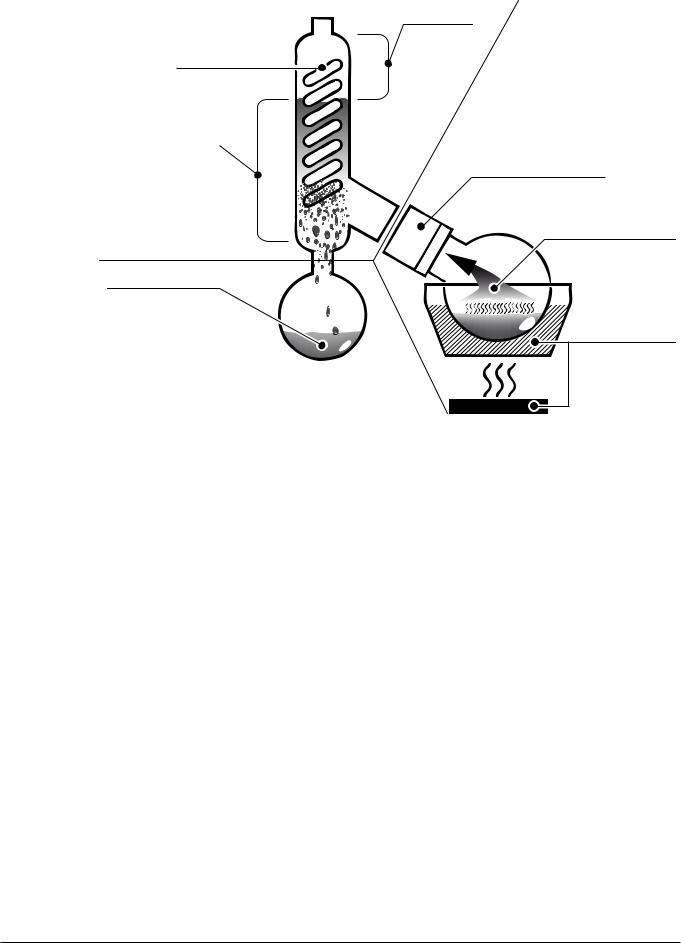
Safety reserve
Cooler with b cooling medium
Optimal condensation
zone range a (~ 80% cooler height)
Rotation drive for evaporating flask
Evaporating solvent
Condensated solvent
Heating bath with heating liquid
c
aEvaporation area
The solvent is heated by means of a heating bath. The turbulent mixing inside the rotating evaporating flask results in an increased evaporation rate.
The drive unit offers a wide range of rotational speeds to perfectly match different evaporation tasks. It also leads to an even mixing of the sample, thus preventing stationary overheating in the flask. When drying powders or pasty materials, the rotation ensures smooth and
thorough drying.
bCooling area
The solvent vapor quickly enters the condenser. Here, the energy in the solvent vapor is transferred to the cooling medium (mostly water), so that the solvent condenses.
cReceiving flask
The receiving flask collects the condensed solvent.
NOTE
For information about optimum distillation conditions see section 6, Operation.
22 |
R-220 SE Operation Manual, Version F |

4 Description of function
4..2 Rotavapor front-side
Various glassware configurations are available for the Rotavapor R-220 SE.
Condenser(s)
Distribution piece
Manual inlet valve |
Shut off tap, large |
Evaporating flask
Condensate cooler
Shut off tap
Receiving flask
Draining valve
23 |
R-220 SE Operation Manual, Version F |

4 Description of function
4..3 Tubing scheme
|
|
4 |
|
|
|
|
|
|
|
1 |
f |
|
|
|
3 |
||
|
|
|
|
||
|
|
2 |
|
|
|
VAPOR TEMP. |
CW TEMP. |
|
|
|
|
LEVEL 2 |
LEVEL 2 |
|
|
e |
|
CW FLOW |
RESERVE |
|
|
||
|
INPUT |
|
|
||
RS-485 |
|
|
|
|
|
RS-485 |
|
|
|
|
|
AERATE |
CW VALVE |
|
d |
|
|
VACUUM VALVE |
|
|
|
|
|
|
|
|
|
|
g |
|
12A |
12A |
12A |
12A |
|
|
F1 |
F2 |
F3 |
F4 |
|
FOAM DET. |
ALARM OUT |
(Type plate) |
|
||
|
|
|
|
||
USB |
|
|
|
AC IN |
|
|
|
|
|
|
|
|
220240 V AC |
|
a |
||
|
MAX. 2A |
|
|
||
|
|
|
|
||
|
|
|
|
b |
|
|
|
|
|
c |
|
24 |
R-220 SE Operation Manual, Version F |

4 Description of function
|
Vacuum / gas circuit |
|
|
|
1 |
Vacuum pump (recommended type: |
For most applications a vaccum is used to significantly reduce |
||
|
|
Vacuum Pump V-710) |
the boiling point of the liquid content inside the evaporating flask. |
|
|
|
|
|
|
|
2 + 3 Aeration / inert gas inlet at the |
The aeration valves at the optional vacuum controller and the |
||
|
|
optional vacuum controller and the |
aeration valve of the Rotavapor are used to aerate the Rotavapor. |
|
|
|
aeration valve |
|
|
Under inert conditions, both aeration inlets must be connected to an inert gas source with regulated output pressure equal to ambient air pressure!
4Vacuum sensor tube at vacuum controller
If a Vacuum Controller V-850 / V-855 is installed, a tube connection must be established to detect the vacuum level inside the glassware.
|
Cooling medium circuit |
|
|
|
|
a |
Chiller or cooling water tap (optional |
When a chiller is used, up to 300 liters of mains water can be |
|
|
|
with cooling water valve) |
saved a day during operation. In addition, higher process safety |
|
|
|
|
and lower solvent emissions due to the constant, low cooling |
|
|
|
|
temperature can be achieved. |
|
|
|
|
|
|
|
|
|
The cooling water valve can also significantly reduce cooling |
|
|
|
|
water consumption by cutting off the water supply when no |
|
|
|
|
cooling is necessary. |
|
|
|
|
|
|
|
b |
Replenishment water tap |
For safety reasons the replenishment water tap must not be |
|
|
|
|
connected when a heating medium different to water is used! |
|
|
c |
Water flow sensor |
Detects cooling water flow when installed. |
|
|
d |
Flow reducing valve |
The valve can be used to reduce the cooling water flow to |
|
|
|
|
achieve the best cooling to water consumption ratio. |
|
|
e |
Condensate cooler |
This cooler inhibits evaporation from the receiving flask. It is part |
|
|
|
|
of some glassware configurations. |
|
fCooler(s)
gCooling water output to sink / return loop to chiller
Depending on the type of glassware configuration, one or more coolers can be connected in serial.
The warmed cooling water can be disposed of into a sink or reused in a closed cooling cycle when a chiller is used.
25 |
R-220 SE Operation Manual, Version F |

4 Description of function
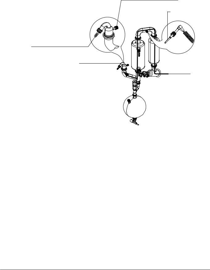
4..3..1 Cooling water routing
General memory aid for cooling water routing
Independent of the number of coolers, the water inlet has to be connected in ascending order starting with the cooler closest to the receiving vessel. The water output is always the upper connector!
Example:
 Output (sink or chiller reflux)
Vapor temp. sensor
Input (water tap or chiller)
Receiving
vessel
The drawing shows the cooling water routing for a setup of three coolers. Other arrangements with single or double cooler setup can be connected accordingly.
!DANGER
Death or serious burns by deflagration of hot heating bath liquids.
•Secure all cooling water hoses against slip off with hose clamps
NOTE
The vapor temperature sensor always has to be installed before the vapor inlet of the first condenser.
26 |
R-220 SE Operation Manual, Version F |

4 Description of function
4..3..2 Vaccum routing
General memory aid for vacuum routing
Independent of the installed glassware setup the vacuum pump has to be connected at the end of the cooling path. Depending on the used setup this can either be subsequently at or after the last condenser.
Example 1:
Connection to vacuum controller |
End of cooling path |
|
Connection to vacuum source |
Vapor temp. sensor |
Vapor path
NOTE
In case the Rotavapor is not equipped with a vacuum controller a blind cap must be used to close the vacuum controller connector to achieve a tight setup. The vapor temperature sensor always has to be installed before the vapor inlet of the first condenser.
27 |
R-220 SE Operation Manual, Version F |
4 Description of function
Example 2:
Connection to vacuum controller
Vapor temp. sensor
Connection to vacuum source
End of cooling path
Vapor path
NOTE
In case the Rotavapor is not equipped with a vacuum controller a blind cap must be used to close the vacuum controller connector to achieve a tight setup. The vapor temperature sensor always has to be installed before the vapor inlet of the first condenser.
28 |
R-220 SE Operation Manual, Version F |
4 Description of function
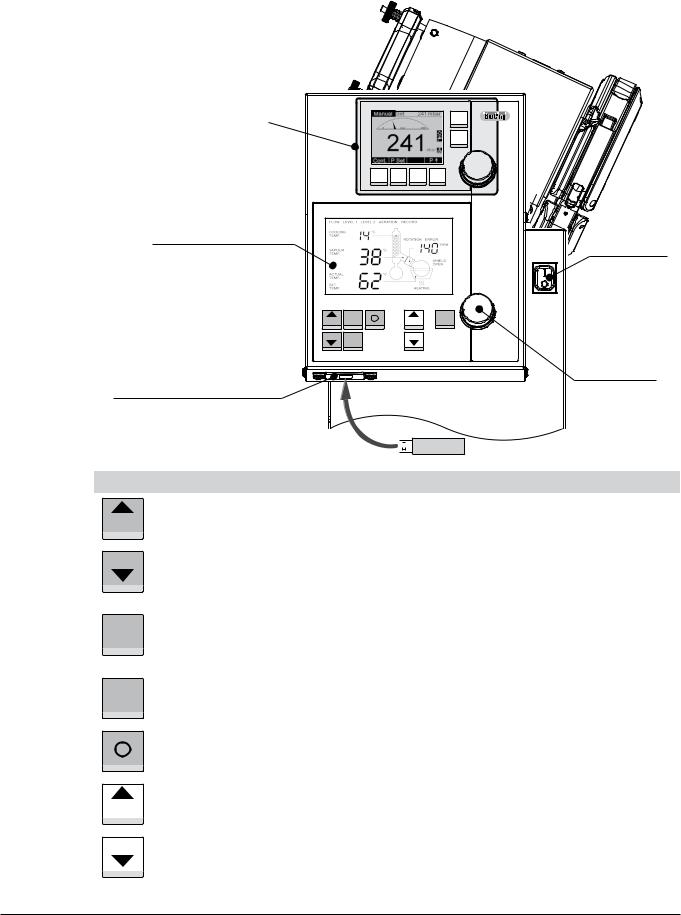
4..4 User interface front-side
Vacuum Controller V-850 / V-855 *
System parameter display and functional buttons
USB socket for recording **
|
|
|
|
Start |
|
|
|
|
|
Stop |
|
|
|
|
|
|
ON / OFF switch |
Temp. |
Heater |
Record |
Lift |
Rotation |
|
|
ON/OFF |
|
|
ON/OFF |
|
UP |
|
|
UP |
|
|
DOWN |
AERATE |
|
DOWN |
Rotavapor |
Turning knob to |
|
|
|
|
||
|
|
|
|
adjust rotational |
|
|
|
|
|
R-220 SE |
|
|
|
|
|
|
|
|
|
|
|
|
speed |
*Not included in Basic version
**Optional accessory


 USB PEN Drive
|
|
|
|
Functionality |
|
|
|
|
|
|
|
|
UP |
|
Increases the set temperature of the heating bath |
||
|
|
|
|
|
|
|
|
|
|
|
|
|
DOWN |
|
Decreases the set temperature of the heating bath |
||
|
|
|
|
||
|
|
|
|
|
|
|
|
|
|
|
|
|
|
|
|
Heater: |
|
|
ON/OFF |
|
Switches the heating bath ON / OFF |
||
|
|
|
|
Rotation: |
|
|
|
|
|
||
|
|
|
|
Switches the rotation drive ON / OFF |
|
|
AERATE |
|
Opens the aeration valve at the Rotavapor rear-side |
||
|
|
|
|
||
|
|
|
|
|
|
|
|
|
|
|
|
|
|
|
|
Starts or stops recording onto a USB PEN Drive. |
|
|
|
|
|
|
|
|
|
|
|
|
|
|
UP |
|
Functionality changes on the basis of the corresponding button description on the display |
||
|
|
|
|
|
|
|
|
|
|
|
|
|
DOWN |
|
Functionality changes on the basis of the corresponding button description on the display |
||
|
|
|
|
||
|
|
|
|
|
|
|
|
|
|
|
|
29 |
R-220 SE Operation Manual, Version F |

4 Description of function
4..5 |
Connection field at the rear-side |
|
|||||
|
|
a |
|
|
b |
|
|
|
|
|
|
|
|
|
e |
|
|
|
|
|
|
|
c |
|
n |
|
|
|
|
|
d |
|
|
|
|
|
|
|
|
|
|
VAPOR TEMP. |
CW TEMP. |
|
|
|
|
|
m |
LEVEL 1 |
LEVEL 2 |
|
|
|
|
|
CW FLOW |
RESERVE |
|
|
|
||
|
|
|
INPUT |
|
|
|
|
|
|
RS-485 |
|
|
|
|
|
|
l |
RS-485 |
|
|
|
|
m |
|
|
|
|
|
|
|
|
|
|
AERATE |
CW VALVE |
|
|
e |
|
|
|
VACUUM VALVE |
|
|
|
|
|
|
|
|
|
|
|
|
|
|
k |
|
|
|
|
|
|
|
|
|
|
|
|
|
f |
|
|
|
12A |
12A |
12A |
12A |
|
|
|
|
F1 |
F2 |
F3 |
F4 |
g |
|
|
|
|
|
|
|
|
|
|
|
|
|
|
|
h |
|
|
FOAM DET. |
ALARM OUT |
(Type plate) |
|
||
|
|
|
|
|
|
||
|
j |
USB |
|
|
|
AC IN |
|
|
|
|
|
|
|
||
|
|
|
220240 V AC |
|
|
||
|
|
|
MAX. 2A |
|
|
|
|
|
|
|
|
i |
|
|
|
|
Position |
Drawing |
|
|
|
|
Description |
a
Vapor temperature sensor, measures the entry temperature of the vapor before the condenser.
b
Cooling water temperature sensor. Must be looped-in between cooling water source outlet and cooler/cooler assembly of the Rotavapor.
c |
See master drawing for appearance |
Aerate valve (parallel to controller aeration valve) |
|
and mounting position. |
|||
|
|||
|
|
|
30 |
R-220 SE Operation Manual, Version F |
 Loading...