


Operation Manual
NIRFlex®
N 500
 093020 en

Table of contents
Table of contents
1 |
About this manual . . . . . . . . . . . . . . . . . . . . . . . . |
. . . . . . . . . |
. . . |
. . |
. 7 |
|
|
1.1 |
Trademarks . . . . . . . . . . . . . . . . |
. . . . . . |
. . |
. . |
7 |
|
1.2 |
Abbreviations . . . . . . . . . . . . . . . . |
. . . . . . |
. . |
. |
7 |
2 |
Safety . . . . . . . . . . . . . . . . . . . . . . . . . . . . . . . |
. . . . . . . . . |
. . . |
. . |
. 8 |
|
|
2.1 |
User qualification . . . . . . . . . . . . . . |
. . . . . . |
. . |
. . |
8 |
|
2.2 |
Proper use . . . . . . . . . . . . . . . . |
. . . . . . |
. . |
. . |
8 |
|
2.3 |
Improper use . . . . . . . . . . . . . . . . |
. . . . . . |
. . |
. |
8 |
|
2.4 |
Safety warnings and safety signs used in this manual . . |
. . . . . . |
. . |
. . |
9 |
|
2.5 |
Product safety |
|
|
|
11 |
|
2.5.1 |
General hazards |
|
|
|
11 |
|
2.5.2 |
Warning labels on housing and assemblies . . . . . . |
. . . . . . |
. . |
. |
12 |
|
2.5.3 |
Personal protective equipment . . . . . . . . . . |
. . . . . . |
. . |
. |
13 |
|
2.5.4 |
Built-in safety elements and measures . . . . . . . |
. . . . . . |
. . |
. |
13 |
|
2.6 |
General safety rules . . . . . . . . . . . . . . |
. . . . . . |
. . |
. |
13 |
3 |
Technical data . . . . . . . . . . . . . . . . . . . . . . . . . . |
. . . . . . . . . |
. . . . . |
14 |
||
|
3.1 |
Materials used |
|
|
|
14 |
3.2Technical data basic instrument . . . . . . . . . . . . . . . . . . . . . . . . . . . . 14
|
3.2.1 |
Basic instrument . . . . . . . . . . . . |
. . . . . . . . |
. . |
. |
. 14 |
|
|
3.2.2 |
Computer requirements |
|
|
|
|
15 |
|
3.3 |
Non-fiber optic measuring cells . . . . . . . |
. . . . . . . . |
. . |
. |
. |
15 |
|
3.3.1 |
NIRFlex Solids |
|
|
|
|
15 |
|
3.3.2 |
NIRFlex Solids Transmittance . . . . . . . . |
. . . . . . . . |
. . |
. |
|
. 15 |
|
3.3.3 |
NIRFlex Liquids . . . . . . . . . . . . |
. . . . . . . . |
. . |
. . |
|
16 |
|
3.4 |
Fiber-optic measuring cells and accessories |
|
|
|
|
17 |
|
3.4.1 |
NIRFlex Fiber Optic Solids |
|
|
|
|
17 |
|
3.4.2 |
NIRFlex Fiber Optic Liquids . . . . . . . . |
. . . . . . . . |
. . |
. . |
|
17 |
|
3.4.3 |
NIRFlex Fiber Optic SMA . . . . . . . . . |
. . . . . . . . |
. . |
. |
. |
18 |
4 |
Description of function . . . . . . . . . . . . . . . . . |
. . . . . . . . . . . . |
. . . |
. . |
. |
19 |
|
|
4.1 |
Functional principle . . . . . . . . . . . |
. . . . . . . . |
. . |
. |
. |
19 |
|
4.2 |
Measuring cells and their modes . . . . . . |
. . . . . . . . |
. . |
. . |
|
21 |
|
4.2.1 |
Transflectance mode . . . . . . . . . . |
. . . . . . . . |
. . |
. . |
|
22 |
|
4.2.2 |
Diffuse reflection mode . . . . . . . . . . |
. . . . . . . . |
. . |
. |
|
. 23 |
|
4.2.3 |
Transmission mode . . . . . . . . . . . |
. . . . . . . . |
. . |
. |
. |
24 |
|
4.2.4 |
Diffuse transmission mode . . . . . . . . |
. . . . . . . . |
. . |
. . |
|
24 |
|
4.3 |
Basic instrument . . . . . . . . . . . . |
. . . . . . . . |
. . |
. |
|
. 25 |
|
4.3.1 |
Lamp unit . . . . . . . . . . . . . . |
. . . . . . . . |
. . |
. . |
|
25 |
|
4.3.2 |
Laser unit . . . . . . . . . . . . . . |
. . . . . . . . |
. . |
. . |
|
26 |
|
4.3.3 |
Standard wheel . . . . . . . . . . . . |
. . . . . . . . |
. . |
. . |
|
26 |
|
4.4 |
NIRWare software suite . . . . . . . . . . |
. . . . . . . . |
. . |
. |
|
. 26 |
|
4.4.1 |
Available NIRWare packages . . . . . . . . |
. . . . . . . . |
. . |
. |
|
. 27 |
|
4.5 |
About the software . . . . . . . . . . . |
. . . . . . . . |
. . |
. |
. |
28 |
|
4.5.1 |
NIRWare Control System Service . . . . . . |
. . . . . . . . |
. . |
. . |
|
28 |
|
4.5.2 |
NIRWare software suite . . . . . . . . . . |
. . . . . . . . |
. . |
. |
|
. 28 |
|
4.5.3 |
NIRCal chemometric software |
|
|
|
|
29 |
|
4.6 |
Measuring cells with their add-ons and accessories |
|
|
|
|
29 |
|
4.6.1 |
Operating panel |
|
|
|
|
29 |
|
4.6.2 |
NIRFlex Solids |
|
|
|
|
30 |
3 |
NIRFlex N-500 Operation Manual, Version E |

|
|
|
Table of contents |
||
4.6.3 Petri dish add-on for NIRFlex Solids |
|
|
|
31 |
|
4.6.4 Vial add-on for NIRFlex Solids |
|
|
|
32 |
|
4.6.5 |
Tablet add-on for NIRFlex Solids . . . . . . . . . . |
. . . |
. . . . |
. |
32 |
4.6.6 |
XL add-on for NIRFlex Solids . . . . . . . . . . . . |
. . |
. . . . |
. |
. 33 |
4.6.7 |
XL add-on with iris aperture for NIRFlex Solids . . . . . . |
. . |
. . . . |
. |
. 34 |
4.6.8XL add-on for B+L sample cups for NIRFlex Solids . . . . . . . . . . . . 34
|
4.6.9 External Reference for XL and petri dish add-on |
|
35 |
|
|
4.6.10 |
Spinner add-on . . . . . . . . . . . . . . . . . . . . . . . . |
|
35 |
|
4.6.11 |
Flow-cell adapter add-on . . . . . . . . . . . . . . . . . . . . |
. |
36 |
|
4.6.12 |
NIRFlex Solids Transmittance . . . . . . . . . . . . . . . . . . . |
|
. 36 |
|
4.6.13 Sample plates for the NIRFlex Solids Transmittance |
|
38 |
|
|
4.6.14 |
NIRFlex Liquids . . . . . . . . . . . . . . . . . . . . . . . . |
|
39 |
|
4.6.15 |
NIRFlex Fiber Optic Solids |
|
40 |
|
4.6.16 |
Transflectance adapter for NIRFlex Fiber Optic Solids . . . . . . . . . . . |
|
. 42 |
|
4.6.17 |
NIRFlex Fiber Optic Liquids . . . . . . . . . . . . . . . . . . . . |
|
42 |
|
4.6.18 |
NIRFlex Fiber Optic SMA . . . . . . . . . . . . . . . . . . . . |
. |
44 |
5 |
Putting into operation . . . . . . . . . . . . . . . . . . . . . . . . . . . . . . . . . . . |
. |
45 |
|
|
5.1 |
Transportation lock . . . . . . . . . . . . . . . . . . . . . . |
. |
45 |
|
5.2 |
Requirements concerning the installation site . . . . . . . . . . . . . . |
|
46 |
|
5.3 |
Electrical connection requirements . . . . . . . . . . . . . . . . . |
|
. 47 |
|
5.4 |
Installing the instrument . . . . . . . . . . . . . . . . . . . . . |
|
. 48 |
|
5.4.1 |
Setting up the Ethernet communication . . . . . . . . . . . . . . . . |
|
48 |
|
5.4.2 |
Network integration . . . . . . . . . . . . . . . . . . . . . . |
. |
49 |
|
5.5 |
Installing the measuring cells . . . . . . . . . . . . . . . . . . . |
|
. 50 |
|
5.6 |
Installing the cover of the NIRFlex Solids Transmittance . . . . . . . . . . |
. |
51 |
|
5.7 |
Preparing the transflectance adapter . . . . . . . . . . . . . . . . |
. |
52 |
|
5.7.1 Adjusting the pathlength of the transflectance adapter to the probe head |
|
52 |
|
|
5.7.2 |
Exchanging the spacer ring . . . . . . . . . . . . . . . . . . . . |
|
54 |
|
5.7.3 |
Installing the transflectance adapter to perform measurements . . . . . . . . |
|
54 |
5.8Installing measurement equipment to the NIRFlex Fiber Optic SMA . . . . . . . 55
5.9 |
Starting up the system . . . . . . |
. . . . . . . . . . . . |
. . |
. |
. 56 |
5.9.1 |
System Suitability Test |
|
|
|
56 |
5.9.2 |
Temperature tests in detail |
|
|
|
56 |
5.9.3 |
NIR linearity test . . . . . . . . |
. . . . . . . . . . . . |
. . |
. |
. 56 |
5.9.4 |
Signal-to-noise ratio determination . . |
. . . . . . . . . . . . |
. . |
. |
. 57 |
5.9.5Wavenumber stability test . . . . . . . . . . . . . . . . . . . . . . . . . . . . . . . 57
|
5.9.6 |
SST with NIRFlex Solids Transmittance . . . . . . . . . . . . . . . . |
|
57 |
|
5.10 |
Reference measurements . . . . . . . . . . . . . . . . . . . . |
. |
57 |
6 |
Operation . . . . . . . . . . . . . . . . . . . . . . . . . . . . . . . . . . . . . . . . . |
. |
59 |
|
|
6.1 |
General recommendations for measuring solids |
|
59 |
|
6.2 |
General recommendations for measuring liquids . . . . . . . . . . . . |
. |
60 |
|
6.3 |
Starting a measurement |
|
60 |
|
6.4 |
NIRFlex Solids |
|
61 |
|
6.4.1 |
Reference measurement for the Petri dish add-on |
|
61 |
|
6.4.2 |
Reference measurement for the XL add-on . . . . . . . . . . . . . . |
. |
61 |
|
6.5 |
NIRFlex Solids Transmittance . . . . . . . . . . . . . . . . . . . |
|
. 61 |
|
6.6 |
NIRFlex Liquids . . . . . . . . . . . . . . . . . . . . . . . . |
|
62 |
|
6.7 |
NIRFlex Fiber Optics . . . . . . . . . . . . . . . . . . . . . . |
|
64 |
|
6.7.1 |
NIRFlex Fiber Optic Solids |
|
64 |
|
6.7.2 |
NIRFlex Fiber Optic Liquids . . . . . . . . . . . . . . . . . . . . |
|
65 |
|
6.7.3 |
NIRFlex Fiber Optic SMA . . . . . . . . . . . . . . . . . . . . |
. |
65 |
4 |
NIRFlex N-500 Operation Manual, Version E |

|
|
|
|
Table of contents |
||||
7 |
Maintenance . . . . . . . . . . . . . . . . . . . . . . . . . . . . . |
. . . |
. . . |
. . . . . |
. |
66 |
||
|
7.1 |
Cleaning |
|
|
|
|
|
66 |
|
7.2 |
Housing |
|
|
|
|
|
66 |
|
7.2.1 Optical surfaces and probes |
|
|
|
|
|
67 |
|
|
7.2.2 |
Cleaning of the External Reference . . . . . . . . . . |
. . |
. . |
. . |
. |
. 67 |
|
|
7.2.3 |
Cleaning of the Transflectance adapter . . . . . . . . |
. . |
. . |
. . |
. . |
|
68 |
|
7.3 |
Advanced testing with NIRWare Automatic Diagnose . . . . |
. . |
. . |
. . |
. |
. 69 |
|
|
7.4 |
Lamp module replacement . . . . . . . . . . . . |
. . |
. . |
. . |
. . |
|
70 |
|
7.5 |
Laser unit replacement . . . . . . . . . . . . . . |
. . |
. . |
. . |
. |
. 74 |
|
|
7.6 |
Filter pad replacement |
|
|
|
|
|
77 |
|
7.7 |
Main fuse replacement . . . . . . . . . . . . . . |
. . |
. . |
. . |
. |
. 78 |
|
|
7.7.1 |
Measuring cell fuse replacement . . . . . . . . . . |
. . |
. . |
. . |
. . |
|
78 |
|
7.8 |
NIRFlex Solids |
|
|
|
|
|
79 |
|
7.9 |
NIRFlex Liquids . . . . . . . . . . . . . . . . |
. . |
. . |
. . |
. . |
|
79 |
|
7.10 |
Customer service . . . . . . . . . . . . . . . . |
. . |
. . |
. . |
. |
. 80 |
|
8 |
Storage, transport and disposal . . . . . . . . . . . . . . . . . . |
. . . |
. . . |
. . . . . |
. |
81 |
||
|
8.1 |
Storage and transport |
|
|
|
|
|
81 |
|
8.2 |
Disposal |
|
|
|
|
|
81 |
9 |
Spare parts and accessories . . . . . . . . . . . . . . . . . . . . |
. . . |
. . . |
. . . |
. . |
. |
83 |
|
|
9.1 |
Scope of delivery . . . . . . . . . . . . . . . . |
. . |
. . |
. . |
. |
. 83 |
|
|
9.1.1 |
Interferometer . . . . . . . . . . . . . . . . . |
. . |
. . |
. . |
. |
. |
83 |
|
9.1.2 |
Measuring cells . . . . . . . . . . . . . . . . |
. . |
. . |
. . |
. . |
|
84 |
|
9.1.3 |
Software . . . . . . . . . . . . . . . . . . |
. . |
. . |
. . |
. . |
|
85 |
|
9.1.4 |
Standard accessories . . . . . . . . . . . . . . |
. . |
. . |
. . |
. . |
|
86 |
|
9.1.5 |
Optional accessories . . . . . . . . . . . . . . |
. . |
. . |
. . |
. . |
|
87 |
|
9.2 |
NIRFlex spectrometer . . . . . . . . . . . . . . |
. . |
. . |
. . |
. . |
|
90 |
|
9.3 |
NIRFlex Solids |
|
|
|
|
|
91 |
|
9.4 |
NIRFlex Solids Transmittance . . . . . . . . . . . . |
. . |
. . |
. . |
. |
|
. 92 |
|
9.5 |
NIRFlex Liquids . . . . . . . . . . . . . . . . |
. . |
. . |
. . |
. . |
|
92 |
|
9.6 |
NIRFlex Fiber Optic Liquids . . . . . . . . . . . . |
. . |
. . |
. . |
. . |
|
92 |
|
9.7 |
NIRFlex Fiber Optic Solids |
|
|
|
|
|
92 |
|
9.8 |
NIRFlex Fiber Optic SMA . . . . . . . . . . . . . |
. . |
. . |
. . |
. |
. |
93 |
|
9.9 |
Transflectance adapter . . . . . . . . . . . . . . |
. . |
. . |
. . |
. |
|
. 93 |
10 Declarations and requirements . . . . . . . . . . . . . . . |
. . . . . . . . |
. . . |
. . . |
. . |
94 |
||
10.1 |
FCC requirements (for USA and Canada) . . . . |
. |
. . . . . |
. . |
. . |
. |
. 94 |
10.2 |
Declaration of conformity . . . . . . . . . . |
|
. . . . . . |
. . |
. . |
. |
95 |
5 |
NIRFlex N-500 Operation Manual, Version E |

1 About this manual
1 About this manual
This manual describes the NIRFlex N-500 including its standard software and provides all information required for its safe operation and to maintain it in good working order.
It is addressed to laboratory personnel and operators in particular.
Read this manual carefully before installing and running your system and note the safety precautions in section 2 in particular. Store the manual in the immediate vicinity of the instrument, so that it can be consulted at any time.
No technical modifications may be made to the instrument without the prior written agreement of Buchi. Unauthorized modifications may affect the system safety or result in accidents. Technical data are subject to change without notice.
NOTE
The symbols pertaining to safety are explained in section 2.
This manual is copyright. Information from it may not be reproduced, distributed or used for competitive purposes, nor made available to third parties. The manufacture of any component with the aid of this manual without prior written agreement is also prohibited.
The English manual is the original language version and serves as basis for all translations into other languages. If you need another language version of this manual, you can download available versions at www.buchi.com.
1..1 Trademarks
The following product names and any registered and unregistered trademarks mentioned in this manual are used for identification purposes only and remain the exclusive property of their respective owners:
•NIRFlex® is a registered trademark of BÜCHI Labortechnik AG
•NIRCal® is a registered trademark of BÜCHI Labortechnik AG
•Kimwipes® is a registered trademark of Kimberly Clark
•Meliseptol® is a registered trademark of B. Braun
1..2 Abbreviations
EMEA: European Agency for the Evaluation of Medicinal Products
EP: European Pharmacopoeia
FDA: Food & Drug Administration
MTBF: Mean time between failures
NIR: Near infrared
PMMA: Polymethylmetacrylat
S/N: Signal to noise ratio
USP: United States Pharmacopeia
6 |
NIRFlex N-500 Operation Manual, Version F |

2 Safety
2 Safety
This section introduces the safety concept of the instrument and contains general rules of behavior and warnings from direct and indirect hazards concerning the use of the product.
For the users safety, all safety instructions and safety messages in the individual sections shall be strictly observed and followed. Therefore, the manual must always be available to all persons performing any tasks described herein.
2..1 User qualification
The instrument may only be used by laboratory personnel and other persons who on account of training and professional experience know the potential dangers that can develop when operating the instrument.
Untrained personnel, or persons who are currently being trained, require careful supervision by a qualified person. This Operation Manual serves as a basis for training.
2..2 Proper use
The NIRFlex N-500 has been designed and built as a rugged analysis instrument. It serves to determine the matter and concentration of substances in samples above its measuring tolerance limit (no trace analysis). Thanks to its ruggedness, the instrument is suitable for use on most production floors (at-line, near-line). For suitable environmental conditions see tables of technical data.
The NIRFlex N-500 system can be applied for the following tasks:
Qualitative analysis
•Differentiation of chemically different substances (e.g. raw material testing of incoming goods);
•Differentiation of chemically similar substances or substance grades.
Quantitative analysis
•Determination of quantifiable product properties such as concentrations or physical parameters (viscosity, particle size).
2..3 Improper use
Any other use than the one stated above and any application that does not comply with the technical data is considered to be improper use. Improper use can cause hazardous situations for the operator and / or for the instrument and might cause consequential property damage.
The operator bears the sole risk for any damages or hazards caused by improper use!
In particular, the following uses shall not be permitted
•Installation and use in environments where explosion protection is required
•User repair and maintenance work other than described in this manual
•Reuse of sample material for production that has been in direct contact with non-food safe materials and surfaces
7 |
NIRFlex N-500 Operation Manual, Version F |

2 Safety
2..4 Safety warnings and safety signs used in this manual
DANGER, WARNING, CAUTION and NOTICE are standardized signal words for identifying levels of hazards and risks related to personal injury and property damage. All signal words, which are related to personal injury are accompanied by the general safety sign.
For your safety it is important to read and fully understand the table below with the different signal words and their definitions!
Sign |
Signal word |
Definition |
Risk level |
|
|
|
|
|
|
|
DANGER |
Indicates a hazardous situation which, if not avoided, will result in |
|
|
|
death or serious injury. |
|||
|
|
|
||
|
|
|
|
|
|
WARNING |
Indicates a hazardous situation which, if not avoided, could result |
|
|
|
in death or serious injury. |
|||
|
|
|
||
|
|
|
|
|
|
CAUTION |
Indicates a hazardous situation which, if not avoided, may result |
|
|
|
in minor or moderate injury. |
|||
|
|
|
||
|
|
|
|
|
no |
NOTICE |
Indicates possible property damage, but no |
|
|
practices related to personal injury. |
(property damage only) |
|||
|
|
|||
|
|
|
||
|
|
|
|
Supplementary safety information symbols may be placed in a rectangular panel on the left to the signal word and the supplementary text (see example below).
Space for supplementary safety information symbols.
!SIGNAL WORD
Supplementary text, describing the kind and level of hazard / risk seriousness.
•List of measures to avoid the herein described, hazard or hazardous situation.
•...
•...
Table of supplementary safety information symbols
The reference list below incorporates all safety information symbols used in this manual and their meaning.
Symbol Meaning
General warning
Electrical hazard
LASER emission
8 |
NIRFlex N-500 Operation Manual, Version F |

2 Safety
Symbol Meaning
Explosive gases, explosive environment
Hot item, hot surface
Device damage
Fragile components
Unplug device
Wear protective goggles
Wear protective gloves
Do not dispose as unsorted household waste!
Additional user information
Paragraphs starting with NOTE transport helpful information for working with the device / software or its supplementaries. NOTEs are not related to any kind of hazard or damage (see following example).
NOTE
Useful tips for the easy operation of the instrument / software.
9 |
NIRFlex N-500 Operation Manual, Version F |
2 Safety
2..5 Product safety
The NIRFlex N-500 has been designed and built in accordance with state-of-the-art technology, at the time of development. Safety warnings in this manual (as described in section 2.4) serve to make the user alert to and avoid hazardous situations emanating from residual dangers by giving appropriate counter measures.
However, risks to users, property and the environment can arise when the instrument is damaged, used carelessly or improperly.
Always follow laboratory safety rules. E.g. wear personal protective equipment such as protective eye googles, protective clothing and gloves when working with the instrument.
2..5..1 General hazards
The following safety messages show hazards of general kind which may occur when handling the instrument. The user shall observe all listed counter measures in order to achieve and maintain the lowest possible level of hazard.
NOTE
The instrument contains a laser for wavenumber calibration. When closed the instrument is considered a Class 1 laser product (DIN Standard: GZS values DIN VDE 0837). When the housing is open, the instrument is considered a Class 3R laser product.
Additional warning messages can be found whenever actions and situations described in this manual are related to situational hazards.
!DANGER
Death or serious injuries by use in explosive environments.
•Do not store or operate the instrument in explosive environments
•Remove all sources of flammable vapors
•Do not store chemicals in the vicinity of the device
• Only operate and maintain the device in environment with sufficient ventilation
!WARNING
Serious eye damage by unfiltered LASER emission at open housing.
•Do not operate the instrument with open or damaged housing
!Caution
Minor or moderate injuries by dangerous current.
•Do not spill any liquids over the Measurement Cell connector of the instrument
10 |
NIRFlex N-500 Operation Manual, Version F |

2 Safety
NOTICE
Risk of instrument damage by mechanical shocks.
•Do not move the instrument when it is active
•Do not drop the instrument or its components
•Keep external vibrations away from the instrument
•Do not transport the instrument without transportation lock engaged
2..5..2 Warning labels on housing and assemblies
The following warning sticker(s) can be found on the housing or assemblies of the NIRFlex N-500:
Symbol |
Meaning |
Location |
|
Hot item, hot surface |
Inside housing, next to lamp modules |
LASER emission
Sticker at the rear side
Sticker inside housing, at the LASER module
|
Electrical hazard |
HV supply LASER |
|
|
|
Device labels |
Meaning |
Location |
|
FCC declaration |
Sticker at the rear side |
See text. |
Sticker at the rear side |
LASER emission class Sticker at the rear side
See text.
Sticker on top of the housing, near the Measurement Cell connector.
11 |
NIRFlex N-500 Operation Manual, Version F |

2 Safety
Device labels |
Meaning |
Location |
|
|
LASER emission |
Sticker inside housing, at the LASER module |
|
|
|
|
|
|
|
|
2..5..3 Personal protective equipment
Safety precautions and personal protective equipment might be necessary to comply with industrial safety standards in some working environments. However, for standard operation with the instrument, no additional protective equipment is necessary.
2..5..4 Built-in safety elements and measures
The instrument is equipped with the following safety elements:
•One outer filter elements with covering frame
•Multiple magnet sensors to detect opening of any housing element
•Multiple overtemperature sensors to monitor thermal spots inside the instrument
•Transportation lock of interferrometer
2..6 General safety rules
Responsibility of the operator
The head of the laboratory is responsible for training his/her personnel.
The operator shall inform the manufacturer without delay of any safety-related incidents which might occur during operation of the instrument or its accessories. Legal regulations, such as local, state and federal laws applying to the instrument or its accessories must be strictly followed.
Duty of maintenance and care
The operator is responsible for the proper condition of instrument. This includes maintenance, service and repair jobs that are performed on schedule as described in this manual. Any work, not explicitly described in this manual must be performed by authorized and trained personnel (e.g. service technicians) only.
Spare parts to be used
Use only genuine consumables and spare parts for maintenance to assure good system performance, reliability and safety. Any modifications of spare parts or assemblies are only allowed with the prior written permission of the manufacturer.
Modifications
Modifications to the instrument are only permitted after prior consultation and with the written approval of the manufacturer. Modifications and upgrades shall only be carried out by an authorized Buchi technical engineer. The manufacturer will decline any claim resulting from unauthorized modifications.
12 |
NIRFlex N-500 Operation Manual, Version F |

3 Technical data
3 Technical data
This section introduces the reader to the instrument specifications and the list of materials used.
3..1 |
Materials used |
|
|
|
|
|
|
|
|
Materials used |
|
|
|
Component |
Material designation |
|
|
|
|
|
|
Base plate |
Aluminium / stainless steel |
|
|
|
|
|
|
Wedges |
TeO2 |
|
|
Polarizers |
Glass |
|
|
|
|
|
|
Housing |
Polyurethane foam |
|
|
|
|
|
|
Detector |
InGaAs |
|
|
|
|
|
|
Magnets |
NdFeB |
|
|
|
|
3..2 |
Technical data basic instrument |
|
|
3..2..1 |
Basic instrument |
|
|
|
|
|
|
|
|
Technical data basic instrument |
|
|
|
Dimensions housing ( W x H x D) |
350 x 250 x 450 mm |
|
|
|
|
|
|
Electric power supply |
100−230 VAC ± 10 %, 50/60 Hz, 350 W |
|
|
|
|
|
|
Ambient conditions |
< 80 % relative humidity for T < 31 °C, linear decreasing |
|
|
|
to 67 % at 35 °C, max. 2500 m, for indoor use only |
|
|
|
|
|
|
Ambient temperature |
5−35 °C ( 25 ± 5 °C recommended) |
|
|
|
|
|
|
Pollution degree |
2 |
|
|
|
|
|
|
Installation category |
II |
|
|
|
|
|
|
Spectral range |
800 - 2500 nm (default 1000 - 2500 nm) |
|
|
|
12‘500 - 4‘000 cm-1 (default 10‘000 - 4‘000 cm-1) |
|
|
|
(if not specified otherwise for measuring cell) |
|
|
|
|
|
|
Resolution |
8 cm-1 (with boxcar apodisation) |
|
|
Type of interferometer |
Polarisation interferometer with TeO2 wedges |
|
|
Wavenumber accuracy |
± 0.2 cm-1 (measured with HF gascell at an ambient |
|
|
|
temperature of 25 °C ± 5 °C) |
|
|
|
|
|
|
S/N |
10000 (peak-to-peak noise of a linear corrected baseline |
|
|
|
between 5600−6000 cm-1, measured with NIRFlex |
|
|
|
Liquids, 2 x 64 scans, Blackman apodisation) |
|
|
|
|
|
|
Number of scans/sec. |
2−4 |
|
|
|
|
|
|
Analog digital converter |
24 bit |
|
|
|
|
|
|
Type of lamp/lifetime lamp (MTBF) |
Tungsten halogen lamp / 12000 h (2 x 6000 h) |
|
|
|
|
|
|
Type of laser |
12 VDC HeNe, wavelength at 632.992 nm |
|
|
|
|
|
|
Ethernet connection |
100 Mbit/s |
|
|
|
|
13 |
NIRFlex N-500 Operation Manual, Version F |

3 Technical data
3..2..2 Computer requirements
The spectral data are collected in the NIRWare database on the PC. The following minimum configuration is needed for the PC running the NIRWare Software Suite (1.4):
Computer hardware and software requirements
Windows XP Professional (32-bit only), SP3 or higher / Windows 7 Professional / Ultimate (32-bit only)
Dual Core 2.4 GHz or faster
3 GB RAM or more (2 GB minimum)
10 GB of free harddisk space
CD– ROM drive
2 Network adapter (1 adapter minimum)
Display res.: 1280 x 1024 (1024 x 768 minimum)
Please consider a more powerful computer system if you are working with a bigger amount of data, doing automated (cyclic) measurements or calculating your own calibrations.
3..3 |
Non-fiber optic measuring cells |
|
|
3..3..1 |
NIRFlex Solids |
|
|
|
|
|
|
|
|
Technical data NIRFlex Solids |
|
|
|
Detector |
extended range InGaAs (temperature controlled) |
|
|
|
|
|
|
Electric power supply |
100 - 230 VAC ± 10%, 50/60 Hz, 20 W |
|
|
|
|
|
|
Ambient conditions |
< 80 % relative humidity for T < 31 °C, linear decreasing to 67 % at |
|
|
|
35 °C, max. 2500 m, for indoor use only |
|
|
|
|
|
|
Ambient temperature |
5−35 °C ( 25 ± 5 °C recommended) |
|
|
|
|
|
|
Pollution degree |
2 |
|
|
|
|
|
|
Installation category |
II |
|
|
|
|
3..3..2 |
NIRFlex Solids Transmittance |
|
|
|
|
|
|
|
|
Technical data NIRFlex Solids Transmittance |
|
|
|
Detector |
InGaAs (temperature controlled) |
|
|
|
|
|
|
Electric power supply |
100 - 230 VAC ± 10%, 50/60 Hz, 20 W |
|
|
|
|
|
|
Ambient conditions |
< 80 % relative humidity for T < 31 °C, linear decreasing |
|
|
|
to 67 % at 35 °C, max. 2500 m, for indoor use only |
|
|
|
|
|
|
Ambient temperature |
5−35 °C ( 25 ± 5 °C recommended) |
|
|
|
|
|
|
Pollution degree |
2 |
|
|
|
|
|
|
Installation category |
II |
|
|
|
|
|
|
Spectral range |
12’500 - 6’000 cm-1 |
|
|
|
(recommended range 11’520 - 6000 cm-1) |
|
|
|
800−1660 nm (recommended range 870 - 1660 nm) |
|
|
|
|
|
|
Photometric dynamic range |
0 - 6 AU |
|
|
|
|
14 |
NIRFlex N-500 Operation Manual, Version F |

3 Technical data
Technical data NIRFlex Solids Transmittance (cont.) |
|
Photometric linearity |
The “addition of filter technique” has been used. |
|
A 2% transmission filter and a wavelength standard |
|
(Rare Earth Oxide mixture) were used for the addition. |
|
Both filters were measured individually and together in |
|
series. The addition of the individual measurements has |
|
been compared with the measurement of both filters ihn |
|
series. The difference had been < 2 x 10⁻⁷ T |
|
at 7’876 cm-1 |
Typical signal-to-noise ratio |
rms for spectral segments of 300 cm-1 in the range of |
|
11’000 - 6’500 cm-1 |
open beam |
mean 2 x 10⁻⁵ AU (16 scans; Blackman apodization) |
5 mm white standard |
mean 10 x 10-5 AU (64 scans; Blackman apodization) |
3..3..3 |
NIRFlex Liquids |
|
|
|
|
|
|
|
|
Technical data NIRFlex Liquids |
|
|
|
Detector |
extended range InGaAs (temperature controlled) |
|
|
|
|
|
|
Electric power supply provided from NIRFlex N-500 |
100−230 VAC ± 10 %, 50/60 Hz, 250 W |
|
|
|
|
|
|
Ambient conditions |
< 80 % relative humidity for T < 31 °C, linear |
|
|
|
decreasing to 67 % at 35 °C, max. 2500 m, for indoor |
|
|
|
use only |
|
|
|
|
|
|
Ambient temperature |
5−35 °C ( 25 ± 5 °C recommended) |
|
|
|
|
|
|
Pollution degree |
2 |
|
|
|
|
|
|
Installation category |
II |
|
|
|
|
|
|
Sample temperature range |
Ambient temperature plus 10 °C up to 65 °C |
|
|
|
|
|
|
Reproducibility of set sample temperature |
± 0.5 °C |
|
|
|
|
|
|
Temperature overshoot |
< 5 °C |
|
|
|
|
|
|
Overheating protection, automatic switch-off |
T > 90 °C |
|
|
|
|
|
|
Diameter of measurement spot |
2 mm |
|
|
|
|
|
|
Type of cuvettes to be used |
Standard cuvettes 12.5 x 12.5 x 45 mm with path- |
|
|
|
length of 2 mm, when spacers are used, 1, 5, 10 mm |
|
|
|
cuvettes can be inserted as well |
|
|
|
|
|
|
Time needed to reach a stable control of the set temperature |
Ambient temperature to 65 °C: 15 min |
|
|
|
|
15 |
NIRFlex N-500 Operation Manual, Version F |

|
|
|
3 Technical data |
3..4 |
Fiber-optic measuring cells and accessories |
||
3..4..1 |
NIRFlex Fiber Optic Solids |
|
|
|
|
|
|
|
|
Technical data NIRFlex Fiber Optic Solids |
|
|
|
Detector |
extended range InGaAs (temperature controlled) |
|
|
|
|
|
|
Electric power supply |
100−230 VAC ± 10 %, 50/60 Hz, 20 W |
|
|
|
|
|
|
Ambient conditions |
< 80 % relative humidity for T < 31 °C, linear decreasing |
|
|
|
to 67 % at 35 °C, max. 2500 m, for indoor use only |
|
|
|
|
|
|
Ambient temperature |
5−35 °C ( 25 ± 5 °C recommended) |
|
|
|
|
|
|
Pollution degree |
2 |
|
|
|
|
|
|
Installation category |
II |
|
|
|
|
|
|
Temperature range at probe tip |
0 °C−80 °C |
|
|
|
|
|
|
Standard length of fiber optic probe |
2 m (available up to 5 m) |
|
|
|
|
Accessories
Technical data Transflectance adapter (Fiber Optic Solids)
|
|
Max. operating temperature |
120 °C |
|
|
|
|
|
|
Material |
Transflectance sleeve material: Steel no. 1.4435 |
|
|
|
Spacer ring material: Steel no. 1.4305 |
|
|
|
Transflectance adapter window: Quartz glass |
|
|
|
(Infrasil 303) sealed with fluorine rubber O-rings |
|
|
|
|
|
|
Available pathlengths |
0.5 mm, 1 mm, 1.5 mm |
|
|
|
|
3..4..2 |
NIRFlex Fiber Optic Liquids |
|
|
|
|
|
|
|
|
Technical data NIRFlex Fiber Optic Liquids |
|
|
|
Detector |
extended range InGaAs (temperature controlled) |
|
|
|
|
|
|
Electric power supply |
100−230 VAC ± 10 %, 50/60 Hz, 20 W |
|
|
|
|
|
|
Ambient conditions |
< 80 % relative humidity for T < 31 °C, linear decreasing |
|
|
|
to 67 % at 35 °C, max. 2500 m, for indoor use only |
|
|
|
|
|
|
Ambient temperature |
5−35 °C ( 25 ± 5 °C recommended) |
|
|
|
|
|
|
Pollution degree |
2 |
|
|
|
|
|
|
Installation category |
II |
|
|
|
|
|
|
Temperature range of the probe head at the probe tip |
0 °C−150 °C |
|
|
|
|
|
|
Max. pressure at the probe tip |
6 bar |
|
|
|
|
|
|
Standard length of fiber optic probe |
2 m (available up to 7 m) |
|
|
|
|
|
|
Pathlength |
2 mm |
|
|
|
|
16 |
NIRFlex N-500 Operation Manual, Version F |

3 Technical data
3..4..3 |
NIRFlex Fiber Optic SMA |
|
|
|
|
|
|
|
|
Technical data NIRFlex Fiber Optic SMA |
|
|
|
Detector |
extended range InGaAs (temperature controlled) |
|
|
|
|
|
|
Electric power supply |
100−230 VAC ± 10 %, 50/60 Hz, 20 W |
|
|
|
|
|
|
Ambient conditions |
< 80 % relative humidity for T < 31 °C, linear decreasing |
|
|
|
to 67 % at 35 °C, max. 2500 m, for indoor use only |
|
|
|
|
|
|
Ambient temperature |
5−35 °C ( 25 ± 5 °C recommended) |
|
|
|
|
|
|
Pollution degree |
2 |
|
|
|
|
|
|
Installation category |
II |
|
|
|
|
NOTE
Limit ranges of environmental conditions at the point of measurement highly depend on individual accessories (i.e. process probe, flow cell, etc.).
17 |
NIRFlex N-500 Operation Manual, Version F |

4 Description of function
4 Description of function
This section explains the basic principle of the instrument, shows how it is structured and gives a functional description of the assemblies.
4..1 Functional principle
The NIRFlex N-500 is a modular optical instrument (basic instrument and measuring cell) to determine the matter and concentration of substances in samples.
In detail, the NIRFlex N-500 is a Fourier Transformation Near Infrared spectrometer (FT-NIR). It generates an invisible near infrared interferogram beam which interacts with the molecules of a sample, generating a characteristic feedback. The feedback is picked up via a measurement cell by a detector and mathematically processed via Fourier transformation into a spectrum. This spectrum is used to extract the requested material information.
Inside the spectrometer, a laser beam is used as a high-precision wavelength reference to allow best possible reproducibility and accuracy of detection.
Advantages of FT-NIR polarization inteferometer
•Simultaneous measurement of all wavenumbers giving an improved signal-to-noise ratio
•Higher intensity giving an improved signal-to-noise ratio and short measuring times
•Laser as wavenumber reference giving high wavenumber stability and good data transferability
•Single-beam interferometer without typical double-beam divergence for mechanically and temperature stable beam alignment
•More robust design than standard Michelson interferometer
How the interferogram is generated
An interferogram is an interference pattern of phase-shifted beams. The NIRFlex N-500 is a singlebeam polarisation interferometer, generating its interferogram in four steps:
Step 1— Polarization of the light source output
The polarizer B generates a well-defined polarization output of the undefined polarized light, emitted by the light source A. Thus, only diagonally polarized light is transmitted.
Step 2 — Beam splitting and orthogonal polarization
The polarized light enters a double refracting block (comparator) C. Here, the light is broken down into two, orthogonally polarized components with a small, static phase shift.
Step 3 — Generating the ongoing phase shift
An assembly of two double refracting wedges is arranged after the comparator. Wedge D is stationary, while wedge E is constantly shifted back and forwards by a fast linear-drive. The movement and the geometric arrangement provides a change of thickness in the light path. This leads to an ongoing phase shift between the light beams.
Step 4 — Beam recombination and interferogram output
A second polarizer F converts the phase shifted beams into a single light output with intensity variation – the interferogram.
18 |
NIRFlex N-500 Operation Manual, Version F |
4 Description of function
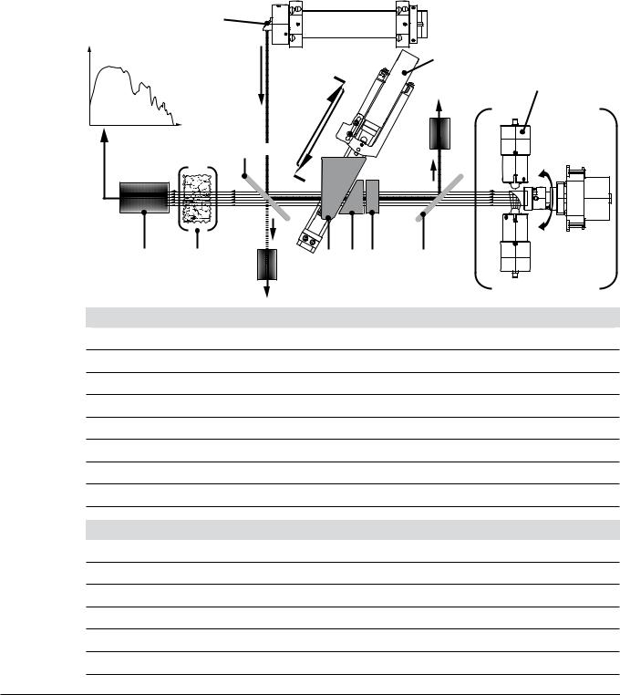
Reference laser control
The laser deliveres a constant, wavelength-stable beam of 633 nm. The laser beam a is coupled into the NIR beam b to pass the interferometer before being decoupled d and analysed by the “Laser feedback sensor” e. A fraction of the beam is splitted at the polarizer b and picked up by an intensity sensor c to monitor the laser beam quality. The position and movement-frequency of the wedge by the linear drive f causes an alternating relative phase shift of the laser light. Being reflected by the second polarizer d, the phase shift generates an alternating amplitude. This alternating amplitude is detected via the the “Laser sensor” e, giving precise information about velocity and (relative) position of the wedge. The feedback signal is used to control the velocity of the linear drive f as well as to set the sampling-points of the NIR interferogram.
a |
LASER – 633 nm |
|
f
Spare lamp
e
F + b 
H G |
E D C B + d |
c |
A |
Effective NIR light path
A NIR light source assembly with spare lamp and motorized parabolic reflector
BFirst polarizer
C Comparator (double refracting block)
D Stationary double refracting wedge
E Moving double refracting wedge
FSecond polarizer
GSample
HInterferogram detector
Reference laser signal path
aLaser output window
b Second polarizator (works as a beam splitter for the laser)
c Laser output-power sensor
dFirst polarizer
eLaser feedback detector
fLinear motor for wedge movement
19 |
NIRFlex N-500 Operation Manual, Version F |

4 Description of function
Data processing and interferogram analysis
The NIR light interacts with the sample G material in different ways, leaving a characteristical fingerprint on the interferogram. At liquids the light is mostly transmitted and at solids reflected. The remaining light is collected by the detector H. The built-in computer further processes the raw signal.
Process steps |
Result |
|
|
Signal preprocessing |
Interferogram |
|
|
Fourier transformation |
Raw spectrum |
|
|
Signal background correction |
Spectrum of sample |
|
|
Chemometric analysis of the spectral data |
Sample analysis |
|
|
Display of the result via NIRWare Operator on the attached monitor |
Sample analysis is displayed |
|
|
4..2 Measuring cells and their modes
The NIRFlex N-500 system is of modular design. The interferometer is located in the basic instrument. Different measuring cell modules for different kinds of sample materials can be easily attached to the basic intrument. To choose the best measuring cell for a specific range of samples the optical properties of the sample material must be know.
Measuring cell matrix
Sample characteristics |
Section |
Measuring cell |
Typical application |
(for NIR light) |
|
|
|
|
|
|
|
Diffuse reflection |
4.2.1 |
NIRFlex Solids; |
Predominantly non-translucent |
|
|
NIRFlex Fiber Optic Solids; |
materials such as most tablets, |
|
|
NIRFlex Fiber Optic SMA* |
cereals and powders |
|
|
|
|
Transmission |
4.2.3 |
NIRFlex Liquids; |
Translucent and transparent liquids |
|
|
NIRFlex Fiber Optic Liquids |
|
|
|
NIRFlex Fiber Optic SMA* |
|
|
|
|
|
Diffuse transmission |
4.2.4 |
NIRFlex Solids Transmittance |
Predominantly translucent solids |
|
|
|
such as some tables, crystal |
|
|
|
powders and other light conducting |
|
|
|
materials |
Transflectance |
4.2.5 |
NIRFlex Fiber Optic Solids / NIRFlex |
|
|
Solids with Transflectance Adapter; |
|
|
NIRFlex Fiber Optic SMA* |
Solids with weak diffuse reflection and low transmission rate characteristics
*Depending on the custom accessory and measurement setup
20 |
NIRFlex N-500 Operation Manual, Version F |
4 Description of function
4..2..1 Transflectance mode
Translucent and opaque liquids can be analyzed via transflectance mode. The light penetrates the liquid, is diffusely reflected by the reference plate and passes the sample a second time. The transflected rays contain the spectral information of the sample.
Factors that can influence the measurement:
•Not enough sample material available
•Air bubbles in the measurement path and under the transflectance cover
•Sample not homogeneous or representative
•Temperature of sample material
•Sample cup or transflectance cover inadequate (e.g. cup material and thickness, blind spots, dirt etc.)
NIRFlex Solids:
Sample cup / petri dish
Diffuse reflecting / reference plate
Small, defined gap for liquid samples
NIR light
Detector
NIRFlex Fiber Optic Solids / SMA:
Fiber optics (example)
Small gap for liquid samples
Diffuse reflecting / reference plate
21 |
NIRFlex N-500 Operation Manual, Version F |

4 Description of function
NOTE
•With special accessories, reflection-mode probes can be equipped for transflectance.
•The samples should either be measured at a constant temperature or the temperature influences must be considered during calibration.
•Recommended number of scans: Qualitative calibration: 4−16; quantitative calibration: 16−32
•Most liquid sample materials can be constantly analyzed with the help of a flow-cell adapter.
4..2..2 Diffuse reflection mode
Most non-translucent materials (e.g. solids such as powders, pellets and cereals) can be analyzed via diffuse reflection. The NIR light penetration is limited by the sample material. It interacts with the sample, is refracted and diffusely reflected into the sensor. The reflected rays contain the spectral information of the sample.


 Sample material


NIR light
Detector
Factors that can influence the measurement:
•Not enough sample material available
•Sample not homogenious or representative
•Humidity of sample material
•Temperature of sample material
•Sample cup inadeqate (e.g. cup material and thickness, blind spots, dirt etc.)
NOTE
•The samples should either be measured at a constant temperature or the temperature influences must be considered during calibration.
•Coarse grained samples should be milled before carrying out the measurement. Recommended number of scans: Qualitative calibration: 4−16; quantitative calibration: 16−32;
granules: 64.
22 |
NIRFlex N-500 Operation Manual, Version F |

4 Description of function
4..2..3 Transmission mode
NIR light is sent through a defined pathlength of sample material (e.g. in a cuvette). The transmitted light contains the spectral information. This is the preferred method for testing liquids.
pathlength
Cuvette
NIR light |
Detector |
4..2..4 Diffuse transmission mode
The diffuse transmission mode is a mixture of “diffuse reflection” and “transmission” mode.
The NIR light penetrates the sample:
•is refracted
•diffusely reflected
•diffusely transmitted
The transmitted rays contain the spectral information of the sample.
Sample |
Collecting lens |
NIR light |
Detector |
|
23 |
NIRFlex N-500 Operation Manual, Version F |

4 Description of function
4..3 Basic instrument
The basic instrument consists of the spectrometer unit with the interferometer, the lamp unit with two lamp modules, the laser unit and electronic boards. The Instrument Software (embedded software) controls the spectrometer and communicates with the PC running NIRWare and with the measuring cell. It controls all actors (stepper motor, heating, etc.) and sensors (light barrier, temperature sensor, etc.) in the measuring cell. The sensor is part of the measuring cell.
a b c
4
e |
g |
|
|
f |
a Main switch |
e Ethernet connection |
b Primary fuses |
f Interfaces for service intervals (USB 1, USB 2, KBD, MS, |
c Power supply socket |
VGA, COM) |
d Type plate with serial number |
g Ventilation filter |
4..3..1 Lamp unit
The lamp unit comprises two lamp modules:
•A primary lamp module, which is normally in use.
•A secondary lamp module, which is only in use during failure of the primary lamp module.
When the NIRWare software detects a lamp failure, it automatically switches to the secondary lamp module. Until the primary lamp module has been exchanged the spectrometer measures spectra with the secondary lamp module.
The operator will be reminded to exchange the primary lamp module, which he can easily do by himself, see section 7.4. The secondary lamp module can only be exchanged by service personnel. The hours of operation are logged separately for each lamp module. The lifetime of the lamps is about 6000 h each.
24 |
NIRFlex N-500 Operation Manual, Version F |

4 Description of function
4..3..2 Laser unit
The laser unit comprises:
•Laser tube
•High voltage power supply
The intensity of the laser light is continuously checked. When it falls below a certain threshold, the operator has to change the laser, see section 7.5. The hours of operation are logged.
The typical lifetime of a laser is about 20000 h.
4..3..3 Standard wheel
Standard wheel
Every NIRFlex N-500 is equipped with a standard wheel with standards that are used for the System Suitability Test (SST).
The standards within the wheel have the following functions:
•Wavelength standard (PMMA) to check the wavelength accuracy.
•Open beam for normal measurements.
•Five different grey standards to check the linearity.
The software is designed for the automatic use of the standard wheel, i.e. the operator does not have to start one of the above mentioned tests manually, to ensure proper measurement of the SST and NADIA.
4..4 NIRWare software suite
NIRWare is the interface program suite between the instrument and the operator. All program parts are hosted on an external PC. The PC communicates with the spectrometer via internal network adapter.
NOTE
•A second network interface at the PC is recommended to connect the NIRFlex N-500 to a local PC network, e.g. for data backup or to communicate with enterprise resource planning etc.
•It is recommended to turn off all power saving options. For Windows XP: In the Control Panel of the operating system open the dialog Power Options Properties and select Power schemes Always On.
25 |
NIRFlex N-500 Operation Manual, Version F |

4 Description of function
About the external PC
The external PC must run Windows® XP or Windows® 7 as operating system and meet the system requirements (see technical data, section 3.2.1). The NIRWare software suite must be installed successfully on the computer. The database might be installed on a network drive, to be accessible by different spectrometer.
4..4..1 Available NIRWare packages
Two predefined NIRWare packages are available for the NIRFlex N-500:
Available NIRWare packages
|
Basic |
Advanced |
|
|
|
NIRWare Operator |
x |
x |
|
|
|
NIRWare Management Console |
|
|
|
|
|
Application Designer |
x |
x |
|
|
|
Sample Manager |
x |
x |
|
|
|
Administrative Tools |
x |
x |
|
|
|
Security Designer |
x |
x |
|
|
|
Library Designer |
|
x |
|
|
|
Regulatory Kit |
|
x |
|
|
|
Each package includes the following program elements by default:
•Operator interface, to run routine analysis
•Administrative tools
•Report templates
•Comprehensive database with analysis data and other
The NIRWare Basic package offers the minimum requirements to use the NIRFlex N-500 FT-NIR system. This package is recommended for routine analyses with pre-calibrated applications or as satellite systems in a large application network.
The NIRWare Advanced package offers all components to comply with pharmaceutical requirements based on a lifecycle concept. It is recommended to complete this package with the NIRCal Chemometric Software, which enables the development of own calibrations. Together with the Library Designer a bunch of possibilities for identity control is available.
26 |
NIRFlex N-500 Operation Manual, Version F |

4 Description of function
4..5 About the software
The NIRWare software meets industrial standards in terms of inner structure combined with a comprehensive and intuitive, wizard guided user interface. It is also ideally suited for many applications in the pharmaceutical, food and feed industry.
Advanced software and system management is done with the NIRWare Management Console tool.
The NIRWare Management Console combines various software modules:
•NIRWare Application Designer to define NIRWare Operator applications
•NIRWare Sample Manager to administrate all samples and reference values
•NIRWare Administrative Tools for applications and calibrations interchange and other administrative tasks
•NIRWare Security Designer to define users and user groups according to custom security policies
Optional:
•NIRWare LIMS to import and export sample information and measurement data
•NIRWare Library Designer is a powerful software module for substance identity control using full spectral comparison. It is designed for the development of spectral libraries tailored to individual user requirements.
•NIRWare Regulatory Kit provides all components to comply with pharmaceutical regulations.
4..5..1 NIRWare Control System Service
The NIRWare Control System Service controls the complete system. It runs in the background as a service. Normally there is no user interaction necessary.
4..5..2 NIRWare software suite
The PC is running the NIRWare Software Suite. NIRWare is the interface between the instrument and the operator. All software tools are included, like Administrative Tools, report templates, elements to create new applications and to run routine analyses, and the database to save all results and data. The outstanding features of NIRWare are its logical structure, an industry-standard design and at the same time an easy to understand user interface.
The NIRWare Software Suite comprises the following modules:
•NIRWare Management Console combines various software modules:
–– NIRWare Application Designer defines the applications performed using NIRWare Operator
–– NIRWare Sampe Manager administers all samples and reference values
–– NIRWare Administrative Tools imports and exports applications and calibrations and is used for other administrative work
–– NIRWare Security Designer is used for the administration of users and user groups and for the definition of security policies
•Optional modules for the NIRWare Management Console:
–– NIRWare Library Designer is a powerful software module for identity control using full spectral comparison. It is designed for the development of spectral libraries tailored to individual user requirements.
–– NIRWare Regulatory Kit provides all components to comply with pharmaceutical regulations.
27 |
NIRFlex N-500 Operation Manual, Version F |

4 Description of function
4..5..3 NIRCal chemometric software
NIRCal is a modern chemometric software package for use with Buchi FT-NIR Spectrometers. It can be used for qualitative and quantitative applications. For method development a lot of comprehensive pretreatments are available. However, the software is easy to use even for novices. The Calibration Wizard guarantees the development of reproducible calibrations. Complex calibrations and interpretations are greatly simplified by the use of wizards, which automate standard procedures and help to develop calibrations.
4..6 Measuring cells with their add-ons and accessories
The modulated light coming from the interferometer interacts with the sample. The light is then detected in the measuring cell and the data is sent to the basic instrument.
The measuring cell has its own power supply and is galvanically isolated from the basic instrument. It can be swapped without switching off the basic instrument and is automatically identified (plug & play).
4..6..1 Operating panel
Each measuring cell is equipped with an operating panel:
a
b
c
a LED |
c STOP button |
b START button |
|
Operating panel of a measuring cell |
|
The START button is used to start a measurement without using a PC keyboard.
The STOP button is used to stop a measurement without using a PC keyboard.
An LED informs the user about the current instrument state:
Red: Instrument is in error state
Green: Instrument is ready to use
Green flashing: Instrument is busy measuring
Yellow: Power is on but the instrument is not yet initialized by the NIRWare software
For a description of the LEDs at the handle of the fiber optic, see sections 4.6.15 and 4.6.17.
28 |
NIRFlex N-500 Operation Manual, Version F |

4 Description of function
4..6..2 NIRFlex Solids
List of NIRFlex Solids add-ons
|
Spinner / Petri dish |
Vial add-on |
Tablet add-on |
XL add-on |
Flow cell |
|
add-on |
|
|
|
|
|
|
|
|
|
|
Max. number of samples per |
1 |
6 |
10 |
1 |
1 |
sequence |
|
|
|
|
|
|
|
|
|
|
|
Measurement based on |
x |
x |
x |
x |
- |
diffuse reflection |
|
|
|
|
|
|
|
|
|
|
|
Measurement based on |
x |
- |
- |
- |
x |
transflectance |
|
|
|
|
|
|
|
|
|
|
|
Measurement with petri |
x |
- |
- |
- |
- |
dishes |
|
|
|
|
|
|
|
|
|
|
|
Measurement with vials |
- |
x |
- |
- |
- |
|
|
|
|
|
|
Measurement of tablets |
- |
- |
x |
- |
- |
|
|
|
|
|
|
Measurement using small |
- |
- |
- |
x |
- |
plastic bags |
|
|
|
|
|
|
|
|
|
|
|
Internal reference |
x |
- |
- |
x |
x |
|
|
|
|
|
|
External Reference |
x |
x |
x |
x |
x |
|
|
|
|
|
|
Sample dimensions |
Spinner 34 mm |
Glass vials |
Tablets |
|
>0.3 ml |
|
Petri dish 100 mm |
10−15 mm |
5−10 mm |
|
|
|
|
|
|
|
|
|
|
|
|
|
|
The NIRFlex Solids is the ideal configuration to measure solid samples like powders, pastes and pellets in diffuse reflection mode. The measuring cell for solids allows the use of different add-ons for specific sample containers.
The software automatically detects the type of add-on in use as soon as the corresponding application is started in the NIRWare Operator.
For a description of the add-ons to be used with the NIRFlex Solids, see section 4.6.3 to 4.6.8.
29 |
NIRFlex N-500 Operation Manual, Version F |
 Loading...