


 Loading...
MD-600 Series
MD-621, MD-631
General-purpose AC Servomotor for Industrial Sewing Machines
Integral model
<<Product Manual>>
Contents
1.Outline 1
2.Features 1
3. Model configuration 2
4.Combinations with sewing machines 4
5.Components 4
6.Automatic presser lifter operations and treadle operations 5
7. DIP switch functions and selecting a pulley 5
8.Using the box built-in panel 6
1.Part names and panel key functions 6
2.Using the machine head setting mode 9
3.Initialization mode 13
4.Memory switch setting mode and parameter setting mode 14
5.Speed setting mode, I/O check mode and ROM ver. mode setting 15
9.Memory switch list 16
10.Parameter list 23
11.List of speed setting modes 30
12.List of input/output check modes 31
13.List of error displays 34
14.Special setting mode (high-speed setting mode) 35
15.Special setting mode (pulley diameter setting mode) 36
16.Special setting mode 38
17.List of special memory switches 41
18.Input/output assignment table for each sewing machine 43
19.Error display mode 45
20.Relation with F panel 46
21.Changing the solenoid voltage 46
22.Miscellaneous 46
23.Comparison of new and old functions with MD601, MD611 47
24.Spare parts list (MD-621, 631) 53
From the library of Superior Sewing Machine & Supply LLC - www.supsew.com
1. Outline
While the current MD601/611 Series is a dedicated motor for each sewing machine model, the general-purpose thread trimming motor MD621/MD631 with general-purpose functions is a model with integrated functions.
This motor can be mounted on the machine and used by reading in the sewing machine model name. This motor is applicable for lockstitch sewing machines, special applications, chain stitch sewing machines and overlock sewing machines. (Refer to the list of machine head setting modes for details on the usable sewing machines.) By adding the optional functions, expanded functions can be used with the sewing machine and peripheral devices. The motor power is 550W, and the different voltage specifications are the same as the conventional models.
2. Features
1.Mounting on lockstitch, special, thick fabric, chain stitch or overlock sewing machines
This motor can be set on each sewing machine with the machine head setting mode.
Using key operations on the box built-in panel, select the sewing machine model name from machine head setting mode.
When the model name is set, the sewing machine model's thread trimming timing, input/output assignment, rotation speed, motor forward rotation/reverse rotation and motor's optimum torque, etc., will be set automatically.
2. Input/output signal functions can be selected and functions can be set
The optional inputs and optional outputs can be set with the box built-in panel.
3.1Selecting the optional input/output functions
3.2Setting the optional output timing
3.3Setting the trigger (ON or OFF) conditions
3.4Setting the time
3.5Selecting the output operations (timer, momentary, alternating operation, etc.)
3.6Setting the input/output signal logic
Note) Refer to the Product Manual Technical Information II for details on setting these functions.
Refer to the Instruction Manual for the connector layout diagram.
3.The panel built into the control box has functions equivalent to the F-40 panel.
4.The F-20, F-40 or F-100 panels can be used as options.
The fabric end sensor II (connected to F panel), fabric end sensor IV, B sensor, bobbin thread detector, and standing work treadle can be used.
– 1 –
From the library of Superior Sewing Machine & Supply LLC - www.supsew.com

3. Model configuration
MD-6□1

 2: Single-phase 50/60 Hz common (Voltage 100V, 110V, 220V, 230V, 240V) 1 3: 3-phase 50/60 Hz common (Voltage 200V, 220V, 380V, 400V, 415V) 2
1: The 220V, 230V and 240V specifications are common by reinserting the connector internally.
2: The 380V, 400V and 415V specifications are common by reinserting the connector internally.
Product specification code (Export specifications)
137-6 1-711- |
|
|
|
|
|
|||||
|
|
|
|
|
Last digit (single-phase voltage) |
Last digit (3-phase voltage) |
||||
|
|
|
|
|
1: 110V |
|
Taiwan, Mexico |
1: 220V |
|
Taiwan, Mexico, |
|
|
|
|
|
|
|
||||
|
|
|
|
|
|
|
|
|
|
Hong Kong, Korea |
|
|
|
|
|
2: 110V |
OCR |
USA |
2: 220V |
OCR |
USA |
|
|
|
|
|
3: 110V |
SJT |
Canada |
3: 220V |
SJT |
Canada |
|
|
|
|
|
4: 230V |
|
Germany, UK, |
4: 400V |
|
Germany, UK, |
|
|
|
|
|
No switches |
France, Italy, Spain, |
No switches |
France, Italy, Spain, |
||
|
|
|
|
|
CE |
|
Portugal |
CE |
|
Portugal |
|
|
|
|
|
5: 220V |
|
Southeast Asia, etc. |
5: 380V |
|
China, Thailand, |
|
|
|
|
|
|
|
Middle East, Turkey, |
|
|
Vietnam, Zimbabwe |
|
|
|
|
|
|
|
Hong Kong, Brazil |
|
|
|
|
|
|
|
|
6: |
|
|
6: 380V |
OCR |
South Africa |
|
|
|
|
|
7: 230V |
|
Singapore |
7: |
|
|
|
|
|
|
|
8: 230V |
|
Greece, |
8: |
|
|
|
|
|
|
|
|
|
New Zealand |
|
|
|
|
|
|
|
|
9: |
|
|
9: |
|
|
|
|
|
|
|
0: 240V |
|
Australia, |
0: 415V |
|
Australia |
|
|
|
|
|
|
|
Southeast Asia |
|
|
|
|
|
|
|
|
Last two digits |
(general-purpose |
specifications, motor pulley diameter, |
|||
|
|
|
|
|
treadle type, packaging) |
|
|
|
||
|
|
|
|
|
G : Pulley ø105 treadle (forward 1st step, backward 2nd step) |
|||||
|
|
|
|
|
Shipped with no machine head setting |
|
|
|||
|
|
|
|
|
F : Pulley ø90 treadle (forward 1st step, backward 2nd step) |
|||||
|
|
|
|
|
||||||
|
|
|
|
|
Shipped with no machine head setting |
|
|
|||
|
|
|
B891 series specifications |
|
|
|
||||
|
|
|
|
|
|
|||||
-752-4 |
|
(sewing machine and set specifications, packaging) |
||||||||
|
|
|
|
|
||||||
B891 series specifications pulley ø80 treadle (forward 1st step, backward 2nd step) 3500rpm
Machine head set (Set to B891) With B891 synchronizer
Model indication on packaging cardboard box General-purpose specifications : MD6 1-1G B891 specifications : MD6 1-14
The motor pulley diameter is identified with G and F in the 11-digit specifications. (G indicates ø105 and F indicates ø90.)
There are two motor pulley diameters for the general-purpose specifications. Select the specifications according to the sewing machine model.
Motor pulley diameter ø105 |
B276 Covering series, SBL, overlock series |
Motor pulley diameter ø90 |
B776, B291, B942, B842, B737 |
Motor pulley diameter ø80 |
B891 series |
|
– 2 – |
From the library of Superior Sewing Machine & Supply LLC - www.supsew.com

(Note 1) The B891 series specifications do not have the outer panel F-40. The built-in panel is used.
If the outer panel is required, purchase it as an independent part. (F-40HB panel, panel installation plate) The model code is 137-207-712-16.
(Note 2) The motor pulley is an aluminum taper pulley. A commercially-available taper pulley can be used.
(Note 3) The motor pulley differs according to each sewing machine model. Refer to the separate list of machine head setting modes to select and use the appropriate motor pulley diameter. Use of a non-specified pulley will prevent the sewing machine from operating in the optimum state.
MD-6□1

 2: Single phase 50/60 Hz Voltage 100V 3: 3-phase 50/60 Hz Voltage 200V
Product specification code (Domestic specifications)
137-6 1-710-
Last digit and last two digits (general-purpose specifications, motor pulley diameter, treadle type, packaging)
G7: Pulley ø105 treadle (forward 1st step, backward 2nd step)
Shipped with no machine head setting
F7: Pulley ø90 treadle (forward 1st step, backward 2nd step)
Shipped with no machine head setting
-752-07 B891 series specifications (sewing machine and set specifications, packaging)
B891 series specifications pulley ø80 treadle (forward 1st step, backward 2nd step) 3500rpm
Machine head set (Set to B891) With B891 synchronizer
Model indication on packaging cardboard box General-purpose specifications : MD6 1-1 B891 specifications : MD6 1-1
The motor pulley diameter is identified with G and F in the 11-digit specifications. (G indicates ø105 and F indicates ø90.)
There are two motor pulley diameters for the general-purpose specifications. Select the specifications according to the sewing machine model.
Motor pulley diameter ø105 |
B276 Covering series, SBL, overlock series |
Motor pulley diameter ø90 |
B776, B291, B942, B842, B737 |
Motor pulley diameter ø80 |
B891 series |
(Note 1) The B891 series specifications do not have the outer panel F-40. The built-in panel is used.
If the outer panel is required, purchase it as an independent part. (F-40HB panel, panel installation plate) The model code is 137-207-712-06.
(Note 2) The motor pulley is an aluminum taper pulley. A commercially-available taper pulley can be used.
(Note 3) The motor pulley differs according to each sewing machine model. Refer to the separate list of machine head setting modes to select and use the appropriate motor pulley diameter. Use of a non-specified pulley will prevent the sewing machine from operating in the optimum state.
– 3 –
From the library of Superior Sewing Machine & Supply LLC - www.supsew.com

4. Combinations with sewing machines
4.1Combination with Brother sewing machine
(1)Single needle lockstitch sewing machine (forward rotation)
B737 (B201/B755), B791, B774, B722, B724, B748A, B798 (B728), B772A, B778A, B781, B852, B883
(2)Twin needle lockstitch sewing machine (forward rotation) B842, B845, B872, B875, B847, B848, B837, B877, B878
(3)Overlock sewing machine (reverse rotation)
(4)Post type sewing machine (forward rotation) C51, P73, P81
(5)Special sewing machines
Hem sewing machine, B776 (forward rotation)
Unison feed sewing machine, B891, B892, B894 (forward rotation) Covering sewing machine, B256, B276 (reverse rotation)
Chain stitch sewing machine, B291 (forward rotation), B942 (reverse rotation) Overlock sewing machine, SBL (reverse rotation)
4.2Built-in panel
Tacking and set length stitching can be set. (Functions equivalent to F-40)
The machine head can be set. The rotation speed, memory switch, parameters and input/output, etc., can be set.
4.3Operation panel (option)
F-20, F-40 or F-100 can be connected.
The fabric end sensor II, fabric end sensor IV, B sensor and bobbin thread sensor can be connected.
4.4Standing work pedal (option)
The variable speed pedal or two-speed pedal can be connected.
4.5Input/output
Solenoid output : 4 outputs (thread trimming, thread wiper, reverse rotation, presser lifter) +
|
|
4 option outputs |
Input signal |
: |
3 signals (safety switch, emergency stop switch, tacking prohibit signal) + |
|
|
12 option signals |
Output signal |
: |
8 option signals (open collector output) |
5. Components
|
MD621/631 |
MD601/611 |
|
Motor assembly |
550W |
400W standard, 550W special |
|
|
ø80, ø90, ø105 |
ø80, ø90, ø105 |
|
Pulley |
ø80 is for B891 series |
ø80 is for B891 series |
|
ø90 is standard (ø105) |
ø90, ø105 |
||
|
|||
|
ø105 is for Covering series, overlock |
ø105 is for Covering series, overlock |
|
|
Control PCB has been newly added |
Use not possible |
|
|
Power supply PCB |
← |
|
Control section |
Treadle unit has been newly installed |
Use not possible |
|
|
Transformer has been newly installed |
Only 30V cannot be used |
|
|
(30V, 24V) |
|
|
|
Built-in panel has been newly installed |
None |
|
|
Motor fixing frame |
← Color is different |
|
Box |
Box top (ADC) |
← Color is different |
|
Box bottom (plastic) |
← Color is different |
||
|
|||
|
Front lid |
Use not possible |
|
|
– 4 – |
|
From the library of Superior Sewing Machine & Supply LLC - www.supsew.com

6. Automatic presser lifter operations and treadle operations
If using a solenoid-type or pneumatic-type presser lifter device, make the following settings.
1.Set DIP switch 1-3 on the control PCB to ON.
ON: Needle starts moving after the presser lifter is lowered. (Includes delay time)
2.If you would like to use pressure variation at the forward 1st step to raise and lower the presser foot using the treadle
At the time of shipment, this is set to the forward 1st step, so use a screwdriver to press inside the hole at the bottom of the treadle lever on the treadle unit. The spring position at the forward 1st step will be changed automatically to the forward 2nd step. (The treadle can then be used without needing to be removed.)
Note: When using the forward 2nd step setting, be sure to set DIP switch 1-4 to ON. Because the forward step has been changed from 1st to 2nd, this will set a delay in the motor starting point when the treadle is pressed forward.
3.If using a commercially-available solenoid-type presser lifter device
Use a solenoid with a coil resistance of 5Ω or more. No warranty can be made for correct operation if a solenoid with a resistance of less than 5Ω is used.
If the presser foot is not held in place, set memory switches [37] and [38] to ON in memory switch mode.
4.If using a pneumatic-type presser lifter device
Change the power supply for the 6-pin plug. For the solenoid type, use (1) 40VDC, (4) SOL output, and for the pneumatic type, use (3) 40VDC, (4) SOL output. (Change the power supply between (1) and (3).)
If the presser foot is not held in place, set memory switches [37] and [38] to ON in memory switch mode.
Use a 30VDC valve as the air valve. If you use a 24VDC type, add a 3W – 5W, 220Ω resistor to the valve (to prevent overheating).
7.DIP switch functions and selecting a pulley
Note) Shaded areas indicate default settings. Other settings vary depending on destination and sewing machine specifications.
|
ON |
Presser foot is lowered when treadle is returned to neutral position |
|
DIPSW1-1 |
immediately after thread trimming. (Export specifications) |
||
OFF |
Presser foot is raised and knee switch has priority when treadle is returned to |
||
|
|||
|
neutral position immediately after thread trimming. (Domestic specifications) |
||
|
ON |
Motor pulley diameter Ø90 (except B891/B892/B894) |
|
DIPSW1-2 |
Motor pulley diameter Ø80 (for B891/B892/B894 machine head) |
||
OFF |
Motor pulley diameter Ø105 (except B891/B892/B894) |
||
|
|||
|
Motor pulley diameter Ø90 (for B891/B892/B894 machine head) |
||
DIPSW1-3 |
ON |
Automatic presser lifter device used (with delay time) |
|
OFF |
Automatic presser lifter device not used |
||
|
|||
DIPSW1-4 |
ON |
Treadle depression to forward 2nd step (default 1st). Forward depression |
|
|
voltage ON 2.5V |
||
|
OFF |
Treadle depression to forward 1st step. Forward depression ON voltage 2.0V |
DIP switch 1-1 is set to ON for export specifications and to OFF for domestic specifications.
Selecting the motor pulley (DIP switch 1-2 setting)
Motor pulley diameter (Three standard types: Ø80, Ø90 and Ø105)
Check that the motor pulley diameter matches the setting for DIP switch 1-2.
Note) For a single needle machine head with a maximum sewing speed of 4700 rpm or less, use a Ø90 pulley.
For a single needle machine head with a maximum sewing speed of 4800 rpm or more, use a Ø105 pulley.
For chain stitch sewing machines and overlock sewing machines, use a Ø105 pulley.
For the B891 series of unison feed sewing machines for heavy material, use a Ø80 pulley. (If the machine head type is set to B891 in machine head setting mode, the pulley diameter will be set automatically to Ø80. Therefore, make sure that DIP switch 1-2 is set to ON.)
– 5 –
From the library of Superior Sewing Machine & Supply LLC - www.supsew.com
8. Using the box built-in panel
1. Part names and panel key functions
When the power switch is turned ON, the display will appear as shown in the illustration.
1 to 4 are displayed in the pattern display section.
The icon function (ON/OFF) state, number of tacking stitches (A, B, C, D), the number of set length stitches (E, F) and the stitching speed are displayed at the ABCD display section.
In normal mode, the following operations are then possible.
If [ ] is displayed on the pattern's 7-segment display, or a [
 ] at the [ABCD] 7-segment's lower line, the mode is OFF.
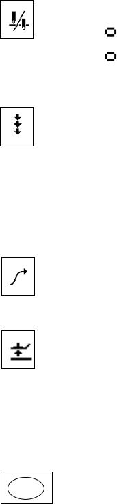
(1) Needle UP/DOWN key
The A [ ] key can be used to switch the needle stop position to UP or DOWN.
When |
|
is displayed : |
OFF (needle stops in DOWN position when |
|
|
|
treadle is at neutral) |
|
|
|
|
When |
|
is displayed : |
ON (needle stops in UP position when treadle |
|
|||
|
|
|
is at neutral) |
|
|
|
(2) Correction key
The B [ ] key can be used to turn correction sewing ON or OFF.
Set to ON if you would like to use the actuator switch for correction sewing when the sewing machine is stopped. Correction sewing (low speed) can then be carried out. This cannot be used after thread trimming when the needle stops in the UP position.
If the actuator switch is pressed while the sewing machine is operating, reverse feed will be carried out.
Note: If using a covering sewing machine with the machine head type set to B256 ("

 "), this key can be used to turn top covering thread trimming/wiping ON and OFF. When set to ON, top covering thread trimming/wiping is enabled, and when set to OFF, it is disabled.
(3) Slow start key
The C [ ] key can be used to turn the slow start ON or OFF.
Set to ON if you would like the slow start to be used at the sewing start (after thread trimming and needle UP stop).
(The first two stitches are sewn at slow speed.)
(4) Presser lifter key
The D [ ] key can be used to raise and lower the presser lifter (ON/OFF). Set to ON if you would like the presser lifter to be raised when the sewing machine stops. When set to ON, the presser foot is always raised when the sewing machine is stopped. This includes when the power is first turned ON, when the sewing machine stops in the needle DOWN position, after thread trimming is completed and when the sewing machine stops in the needle UP position.
This function operates in the same way as the knee switch (shorting/ opening the 1-pin plug of the presser foot 6-pin connector).
Changing the panel display mode
(5) Using the function (FUNC) key
When the FUNC key is pressed, the LEDs are turned ON and OFF in the FUNC following sequence: Sewing speed LED ON, ABCD (tacking number) LED
ON, EF (fixed length number) LED ON, all LEDs OFF.
– 6 –
From the library of Superior Sewing Machine & Supply LLC - www.supsew.com

(6) Sewing speed display mode
Press the FUNC key so that the sewing speed LED is ON.
The current setting value for the sewing speed appears in the "ABCD" display.
The A [ ] key can be used to set the thousands digit, and the B [ ] key can be used to set the hundreds digit.
(The setting range is within the inching speed setting and the maximum sewing speed limit.)
(7) Backtack stitch number display mode
Press the FUNC key again to turn the sewing speed LED OFF and the
ABCD LED ON. If the start tacking, end tacking or continuous tacking LED isON, the number of stitches set for that tacking will appear in the "ABCD"
display.
Press the A [ ] key to set the number in the A column. Press the B [ ] key to set the number in the B column. Press the C [ ] key to set the number in the C column. Press the D [ ] key to set the number in the D column. Each column can be set to a number between 0 and 9. When 9 is reached and the [ ] key is pressed again, the setting returns to 0.
(8) Fixed length stitch number display mode
For patterns 2 to 4, press the FUNC key again to turn the ABCD LED OFF  and the EF LED ON. The number of stitches set for F will appear in the AB columns, and the number of stitches set for E will appear in the CD columns.
Backtack display mode and key operations
(9) Start tacking key
When the start tacking key is pressed, the LED turns ON. The number of start tacking stitches which has been set (0 to 9) will appear in the AB columns.
Note: If using a covering sewing machine with the machine head type set to B256 ("

 "), this key will turn start condense stitch sewing ON and OFF. The number of start condense stitches which has been set (0 to 99) will appear in the AB columns.
(10) End tacking key
When the end tacking key is pressed, the LED turns ON. The number of end tacking stitches which has been set (0 to 9) will appear in the CD columns. (End tacking can be canceled before it is completed.)
Note: If using a covering sewing machine with the machine head type set to B256 ("

 "), this key will turn end condense stitch sewing ON and OFF. The number of end condense stitches which has been set (0 to 99) will appear in the CD columns.
(11) Continuous tacking key
When the continuous tacking key is pressed, the LED turns ON. The number of continuous tacking stitches which has been set (0 to 9) will appear in the ABCD columns. After each cycle has been completed, the thread is trimmed automatically.
(9) to (11) are not available with the B776/SBL.
– 7 –
From the library of Superior Sewing Machine & Supply LLC - www.supsew.com
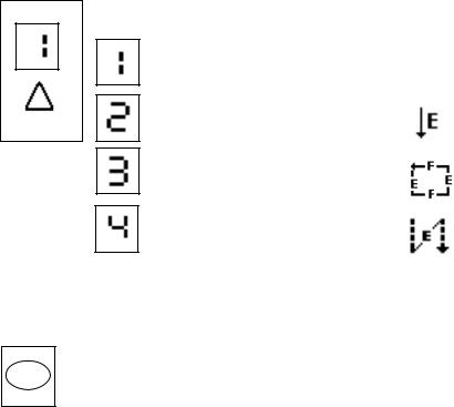
Pattern display mode and key operation
(12) Pattern setting and key operation
The sewing pattern can be set from 1 to 4. The pattern number increases by 1 each time the pattern key is pressed.
Manual mode
Fixed length sewing mode
Label attaching mode
Pleat sewing mode
Patterns (2) to (4) are not available with the B776/SBL.
Accepting settings
(13) Using the SET key
This key is used to accept settings and to end the setting procedure inmachine head setting mode, memory switch mode, parameter mode and
initialization mode.
It can also be used to accept settings and to end the setting procedure in input/output setting mode and special mode.
– 8 –
From the library of Superior Sewing Machine & Supply LLC - www.supsew.com
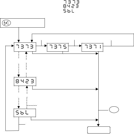
2. Using the machine head setting mode
This product is shipped with the general specifications, so the machine head model is not set. Thus, the machine head model must be set during setup.
Check the sewing machine model, and set the head with the following procedures.
Turn the power switch ON.
Is the built-in panel's power lamp (green) ON?
Is "

 " flashing at the built-in panel's A, B, C, D digits?
The motor will not start even if the treadle is pressed in this state. Call out and set the sewing machine model name in this state.
Setting the machine head |
|
||
" |
" will be flashing. |
" : Machine head type has not been set. |
|
|
|
Display No. " |
|
|
|
Display No. " |
" : Machine head is DB2-B737- 3. |
|
|
Display No. " |
" : Machine head is LT2-B842- 3. |
|
|
Display No. " |
" : Machine head is an SBL overlock. |
|
|
||
|
|
|
|


 Press the B [ ] key to show the next type.


 Press the C [ ] key to show the previous type.
D [ ] key |
D [ ] key |
D [ ] key |
||||||
|
|
|
|
|
|
|
|
|
|
|
|
|
|
|
|
|
|
|
|
|
|
|
|
|
|
|


 B [ ] key


 C [ ] key
D [ ] key |
D [ ] key |
D [ ] key |


 B [ ] key


 C [ ] key
B [ ] key
Press the
SET key to
complete the setting.
Sewing mode
Note) Set the machine head type in machine head setting mode.
Use the B [ ] key to increment the setting, and the C [ ] key to decrement the setting. Press the D [ ] key to set the sub-class.
Press the SET key to accept the setting. Machine head setting mode will then be exited.
Refer to "Machine head setting mode list" for the machine head types.
– 9 –
From the library of Superior Sewing Machine & Supply LLC - www.supsew.com
Checking, setting and changing the machine head
Display No. " |
" : Machine head is DB2-B737- 3. |
Display No. " |
" : Machine head is DB2-B842- 3. |
Display No. " |
" : Machine head is an SBL overlock. |
+ Power switch ON
D [ ] key |
D [ ] key |
D [ ] key |


 B [ ] key (Increment)


 C [ ] key (Decrement)


 B [ ] key
C [ ] key |
Press the |
SET key to
complete the setting.
B [ ] key
Sewing mode
Note) Set the machine head type in machine head setting mode.
Use the B [ ] and C [ ] keys to set the name, and use the D [ ] key to select the sub-class.
Press the SET key to accept the setting. Machine head setting mode will then be exited.
Refer to "Machine head setting mode list" on page 11 for the machine head types.
– 10 –
From the library of Superior Sewing Machine & Supply LLC - www.supsew.com
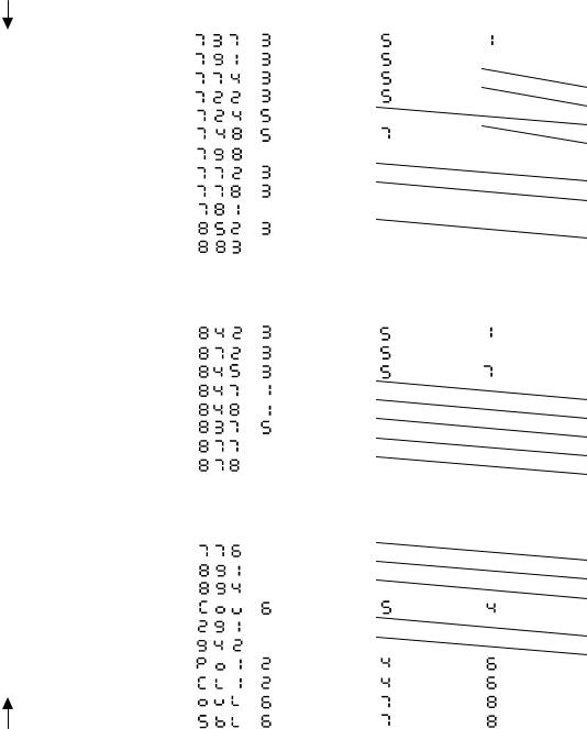
Machine head setting mode list
This table shows the machine head names, maximum sewing speeds and motor pulley diameters.
(1) Factory default setting (no machine head setting)
Machine head |
"ABC" |
"D" display |
Motor pulley |
|
display |
diameter |
|||
|
|
|||
No machine head setting |
– – – |
– |
|
(2) Single needle
Machine head |
"ABC" |
|
"D" display |
|
Motor pulley |
display |
|
|
diameter |
||
|
|
|
|
||
B737/B201/B755 |
|
4700rpm |
3500rpm |
4000rpm |
ø90/ø105 |
B791 |
|
4500rpm |
3500rpm |
|
ø90/ø105 |
B774 |
|
4500rpm |
3500rpm |
|
ø90/ø105 |
B722 |
|
4700rpm |
4000rpm |
|
ø90/ø105 |
B724 |
|
4000rpm |
|
|
ø90 |
B748A |
|
4000rpm |
3000rpm |
|
ø90 |
B798/B728 |
|
None 2000rpm |
|
|
ø90 |
B772A |
|
4700rpm |
|
|
ø90/ø105 |
B778A |
|
4700rpm |
|
|
ø90/ø105 |
B781 |
|
None 4000rpm |
|
|
ø90 |
B852/B853/B854 |
|
4500rpm |
|
|
ø90 |
B883 |
|
None 850rpm |
|
|
ø90 |
(3) Twin needle
Machine head |
"ABC" |
|
"D" display |
|
Motor pulley |
display |
|
|
diameter |
||
|
|
|
|
||
B842 |
|
4000rpm |
3500rpm |
4000rpm |
ø90 |
B872 |
|
3000rpm |
3000rpm |
|
ø90 |
B845/B875 |
|
3000rpm |
3000rpm |
3000rpm |
ø90 |
B847 |
|
4000rpm |
|
|
ø90 |
B848 |
|
3000rpm |
|
|
ø90 |
B837 |
|
3000rpm |
|
|
ø90 |
B877 |
|
None 3000rpm |
|
|
ø90 |
B878 |
|
None 2500rpm |
|
|
ø90 |
(4) Special, heavy material, chain stitch, overlock
Machine head |
"ABC" |
|
"D" display |
|
Motor pulley |
display |
|
|
diameter |
||
|
|
|
|
||
B776 |
|
None 4500rpm |
|
|
ø90 |
B891/B892 |
|
None 3500rpm |
|
|
ø80 |
B894 |
|
None 3500rpm |
|
|
ø80 |
B256/B276 |
|
6000rpm |
5000rpm |
4500rpm |
ø105 |
B291 |
|
None 4500rpm |
|
|
ø90 |
B942 |
|
None 4000rpm |
|
|
ø90 |
P73/P81 |
|
2200rpm |
2400rpm |
2600rpm |
ø90 |
C51 |
|
2200rpm |
2400rpm |
2600rpm |
ø90 |
Overlock |
|
6000rpm |
7000rpm |
8000rpm |
ø105 |
SBL |
|
6500rpm |
7000rpm |
8000rpm |
ø105 |
Note 1) Even if "
 " is used to clear all settings in initialization mode, machine head setting mode will retain the machine head setting which was active before all settings were cleared.
2)Refer to the Instruction Manual for checking methods after machine head setting mode is completed.
3)The machine head type displayed moves down the list each time the B [ ] key is pressed.
4)The machine head type displayed moves up the list each time the C [ ] key is pressed.
5)The motor pulley diameter shown is the outer diameter. Attach the appropriate pulley depending on the machine head type.
DIP switch 1-2 on the control PCB is used to select the pulley size. Set DIP switch 1-2 to match the size of the pulley installed.
– 11 –
From the library of Superior Sewing Machine & Supply LLC - www.supsew.com
Other machine sewing speeds
(1) Single needle
Machine head |
Inching |
Thread |
Slow |
Start/end tacking |
Improved |
|
speed |
trimming |
stopping |
||||
|
|
|
||||
B737/B201/B755 |
215rpm |
215rpm |
215rpm |
1800rpm |
1700rpm |
|
B791 |
↓ |
↓ |
↓ |
↓ |
↓ |
|
B774 |
↓ |
↓ |
↓ |
↓ |
↓ |
|
B722 |
↓ |
↓ |
↓ |
↓ |
↓ |
|
B724 |
↓ |
↓ |
500rpm |
1600rpm |
↓ |
|
B748 |
↓ |
↓ |
215rpm |
1200rpm |
↓ |
|
B798 |
↓ |
↓ |
↓ |
1000rpm |
↓ |
|
B772A |
↓ |
↓ |
↓ |
1800rpm |
↓ |
|
B778A |
↓ |
↓ |
↓ |
↓ |
↓ |
|
B781 |
↓ |
↓ |
↓ |
↓ |
↓ |
|
B852/B853/B854 |
↓ |
185rpm |
↓ |
1200rpm |
↓ |
|
B883 |
250rpm |
170rpm |
250rpm |
250rpm |
500rpm |
(2) Twin needle
Machine head |
Inching |
Thread |
Slow |
Start/end tacking |
Improved |
|
speed |
trimming |
stopping |
||||
|
|
|
||||
B842 |
250rpm |
185rpm |
250rpm |
1000rpm |
1500rpm |
|
B872 |
↓ |
↓ |
↓ |
↓ |
↓ |
|
B845/B875 |
↓ |
↓ |
↓ |
↓ |
↓ |
|
B847 |
↓ |
↓ |
↓ |
↓ |
↓ |
|
B848 |
↓ |
↓ |
↓ |
↓ |
↓ |
|
B837 |
↓ |
↓ |
↓ |
↓ |
↓ |
|
B877 |
↓ |
↓ |
↓ |
800rpm |
↓ |
|
B878 |
↓ |
↓ |
↓ |
↓ |
↓ |
(3) Special, heavy material, chain stitch, overlock
Machine head |
Inching |
Thread |
Slow |
Start/end tacking |
Improved |
|
speed |
trimming |
stopping |
||||
|
|
|
||||
B776 |
215rpm |
215rpm |
800rpm |
1800rpm |
1700rpm |
|
B891/B892 |
250rpm |
185rpm |
250rpm |
800rpm |
1500rpm |
|
B894 |
↓ |
↓ |
↓ |
↓ |
↓ |
|
B256/B276 |
215rpm |
215rpm |
215rpm |
1800rpm |
1700rpm |
|
B291 |
↓ |
↓ |
↓ |
↓ |
↓ |
|
B942 |
↓ |
↓ |
↓ |
↓ |
↓ |
|
P73/P81 |
250rpm |
185rpm |
250rpm |
1000rpm |
1500rpm |
|
C51 |
↓ |
↓ |
↓ |
↓ |
↓ |
|
Overlock |
215rpm |
215rpm |
215rpm |
1800rpm |
↓ |
|
SBL |
↓ |
↓ |
1500rpm |
↓ |
↓ |
– 12 –
From the library of Superior Sewing Machine & Supply LLC - www.supsew.com
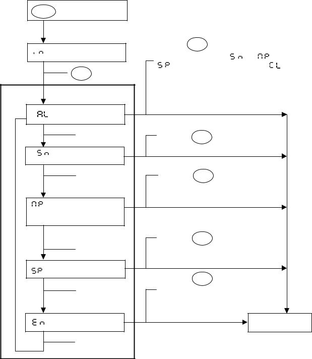
3. Initialization mode
Memory data is stored in the EEPROM. If this data is changed by mistake, you can re-initialize the data in initialization
Setting method
|
FUNC + Power switch ON |
|
|
|
|
|
|
||
[ |
] Initialization mode menu |
Press the |
SET key to start initializing, and |
||||||
carry out each step for [ |
] + [ |
] + |
|||||||
|
|
|
|||||||
|
|
|
[ |
]. When each step is finished, [ |
] will |
||||
|
SET |
key ON |
appear. The display is cleared when you go |
||||||
|
|
|
back to sewing mode. |
|
|
||||
|
Initialization menu |
|
|
|
|
|
|
||
[ |
] Clear all settings |
|
|
|
|
|
|
||
|
B [ ] |
|
Press the |
SET |
key to initialize. |
|
|||
[ |
] Initialize stitch |
|
|
|
|
|
|
||
|
number data |
|
|
|
|
|
|
||
|
|
] |
|
Press the |
SET |
key to initialize. |
|
||
|
B [ |
|
|
|
|
|
|
||
|
|
|
|
Data returns to the data set in |
|
||||
[ |
] Initialize memory |
|
machine head setting mode. |
|
|||||
|
|
|
|
|
|
||||
|
switch and |
|
|
|
|
|
|
||
|
parameters settings |
|
|
|
|
|
|
||
|
|
|
|
Press the |
SET |
key to initialize. |
|
||
|
B [ ] |
|
Data returns to the data set in |
|
|||||
|
|
|
|
machine head setting mode. |
|
||||
[ |
] Initialize speed data |
|
Press the |
SET key to quit the |
|
||||
|
|
|
|
|
|||||
|
|
] |
|
initialization mode. |
|
|
|||
|
B [ |
|
The sewing mode will be entered |
|
|||||
|
|
|
|
|
|||||
|
|
|
|
without the initialization taking place. |
|||||
[ |
] Exit mode |
|
|
|
|
|
Sewing mode |
||
|
B [ ] |
|
|
|
|
|
|
||
Note) Even if [
 ] all clear is executed in the initialization mode, the machine head setting mode will retain the model set before all clear was executed.
– 13 –
From the library of Superior Sewing Machine & Supply LLC - www.supsew.com
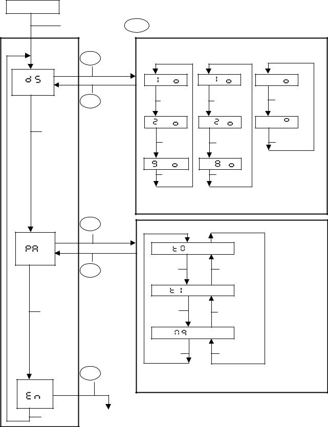
4. Memory switch setting mode and parameter setting mode
When stopped |
|
|
|
|
|
|
|
|
|
|
|
|
|
|
|
|
|
|
While pressing the |
FUNC key, turn the A [ ] key ON. |
|
|
|
|
|
||||||
|
Setting |
|
|
Memory switch setting mode |
|
|
|
|
|
|
|||||
|
mode 1 |
SET |
key ON |
|
|
|
|
|
|
|
|
|
|
|
|
|
|
|
|
|
|
|
|
|
|
|
|
|
|
||
[ |
] |
|
|
|
[ |
- |
] |
[ - |
] |
|
[ |
|
- |
] |
|
|
|
|
|
|
|
|
|
|
|
|
|
|
|||
|
|
|
SET |
key ON |
|
|
] |
|
|
] |
|
|
D [ ] |
||
|
|
|
|
|
A [ |
|
B [ |
|
|
|
|
|
|||
|
|
|
for 2 seconds |
|
|
|
|
|
|
|
|
|
|
|
|
|
|
|
or more to |
[ |
- |
] |
[ |
- |
] |
|
[ - |
] |
|||
|
B [ ] |
finish |
|
|
|
|
|
|
|
|
|
|
|
|
|
|
|
|
|
|
|
|
|
|
|
|
|
|
|
||
|
|
|
|
|
|
A [ ] |
|
B [ ] |
|
|
D [ |
|
|||
|
|
|
|
|
|
|
|
|
|
|
] |
||||
|
|
|
|
|
[ |
- |
] |
[ |
- |
] |
|
|
|
|
|
|
|
|
|
|
|
A [ ] |
|
B [ ] |
|
|
|
|
|
||
|
|
|
|
|
Use the A [ ] and B [ ] keys to set the memory |
||||||||||
|
|
|
|
|
switch number. |
|
|
|
|
|
|
|
|||
|
|
|
|
|
Use the D [ ] key to set to ON or OFF. |
|
|
||||||||
|
|
|
SET |
key ON |
Parameter setting mode |
|
|
|
|
|
|
||||
|
|
|
|
|
|
|
|
|
|
|
|||||
[ |
] |
|
|
|
|
[ |
|
] |
|
|
|
|
|
|
|
|
|
|
SET |
key ON |
|
A [ ] |
|
|
B [ |
|
] |
|
|
|
|
|
|
|
|
|
|
|
|
|
|
|
|
|
|||
|
|
|
for 2 seconds |
|
|
|
|
|
|
|
|
|
|
|
|
|
|
|
or more to |
|
[ |
] |
|
|
|
|
|
|
|
||
|
|
|
finish |
|
|
A [ ] |
|
|
|
|
|
|
|
|
|
|
|
] |
|
|
|
|
|
|
] |
|
|
|
|
||
|
B [ |
|
|
|
|
|
|
B [ |
|
|
|
|
|
||
|
|
|
|
|
|
[ |
|
] |
|
|
|
|
|
|
|
|
|
|
|
|
|
A [ ] |
|
B [ ] |
|
|
|
|
|||
|
|
|
SET |
key ON |
Use the A [ ] and B [ ] keys to set the parameter |
||||||||||
|
|
|
number. |
|
|
|
|
|
|
|
|
|
|||
|
|
|
|
|
|
|
|
|
|
|
|
|
|
||
|
|
|
|
|
Use the C [ ] and D [ ] keys to set to ON or OFF. |
||||||||||
[ |
] |
|
|
|
|
|
|
|
|
|
|
|
|
|
|
|
|
] |
Setting mode 1 exited |
|
|
|
|
|
|
|
|
|
|
||
|
B [ |
|
|
|
|
|
|
|
|
|
|
|
|
|
|
Note) Parameter setting mode cannot be entered until memory switch [01] is set to ON.
Refer to page 16 to 22 for the Memory switch list.
Refer to page 23 to 29 for the Parameter list.
–14 –
From the library of Superior Sewing Machine & Supply LLC - www.supsew.com

5. Speed setting mode, I/O check mode and ROM ver. mode setting
When stopped |
While pressing the |
|
Refer to page 29 for the List of speed setting modes. |
|||
|
|
|
FUNC |
|||
|
|
|
Refer to pages 30 to 32 for the List of input/output check modes. |
|||
|
|
key, turn the B [ ] |
|
|||
|
|
|
|
|
||
|
|
key ON. |
|
Speed setting mode |
||
|
Setting |
SET |
key ON |
Speed symbol display |
|
Setting value display |
|||||||||
|
mode 2 |
|
|
|
|||||||||||
|
|
|
|
|
|
|
|
|
FUNC key ON |
(Inching speed) |
|||||
|
|
|
|
|
|
|
|
|
|
|
|
||||
[ |
] |
|
|
|
|
|
[ |
] |
|
|
|
|
[ |
] |
|
|
|
|
|
|
|
A [ ] |
|
|
|
SET |
key ON |
Use [ ] key |
|||
|
|
|
|
|
|
|
|
|
to change |
||||||
|
|
|
|
SET |
key ON |
|
|
|
B [ |
|
] |
|
|
||
|
|
|
|
|
|
|
|
|
|
|
key ON |
(Thread trimming |
|||
|
|
|
|
for 2 seconds |
|
|
|
|
|
|
FUNC |
||||
|
|
|
|
|
|
|
|
|
|
speed) |
|
||||
|
|
|
|
or more to |
|
[ |
] |
|
|
|
|
[ |
] |
||
|
|
|
|
finish |
|
|
|
|
|
|
|
SET |
key ON |
Use [ ] key |
|
|
|
|
|
|
|
|
|
|
|
|
|
||||
|
B [ |
|
] |
|
|
A [ ] |
|
|
|
|
|
to change |
|||
|
|
|
|
|
|
|
|
|
|
FUNC |
key ON |
(Improved stoping |
|||
|
|
|
|
|
|
|
|
|
B [ |
|
] |
||||
|
|
|
|
|
|
|
|
|
|
|
speed) |
|
|||
|
|
|
|
|
|
|
|
|
|
|
|
|
|
||
|
|
|
|
|
|
|
[ |
|
] |
|
|
|
key ON |
[ |
] |
|
|
|
|
|
|
|
|
|
|
|
|
SET |
Use [ ] key |
||
|
|
|
|
|
|
A [ |
|
] |
|
|
|
|
|
to change |
|
|
|
|
|
|
|
|
|
|
|
|
|
|
|
||
|
|
|
|
|
|
|
|
|
B [ ] |
|
|
|
|
||
|
|
|
|
|
|
Use the A [ ] and B [ ] keys to select the speed for setting. |
|
|
|||||||
|
|
|
|
|
|
Use the A to D [ ] keys to set the speed. |
|
|
|
||||||
|
|
|
|
SET |
key ON |
I/O check mode |
|
|
|
|
|
|
|||
|
|
|
|
|
|
|
|
|
|
|
|
||||
[ |
] |
|
|
|
|
|
|
|
|
Input signal check mode |
|
|
|||
|
|
|
|
[ |
|
. ] |
Use the A [ ] and B [ ] keys to select the |
||||||||
|
|
|
|
|
|
|
|
|
|
|
signal. |
|
|
|
|
|
|
|
|
|
key ON |
|
|
|
|
CD columns show if signal is OFF or ON. |
|||||
|
|
|
|
SET |
|
|
|
FUNC |
key ON |
|
|
|
|
||
|
|
|
|
|
|
|
|
|
|
|
|
|
|
|
Analog voltage check mode |
|
|
|
|
|
|
|
|
|
[ |
] |
|
Use the B [ ] key to select the analog signal |
|||
|
|
|
|
|
|
|
|
|
|
|
|
|
|
|
number. |
|
|
|
|
|
|
|
|
|
|
|
|
|
|
|
Use the A [ ] key to change the display mode. |
|
|
|
|
|
|
|
|
|
|
|
|
|
|
|
|
|
|
|
B [ ] |
|
|
|
|
|
|
|
|
|
CD columns shows voltage value. |
||
|
|
|
|
|
|
|
|
|
FUNC |
|
key ON |
||||
|
|
|
|
|
|
|
|
|
|
|
|
|
|||
|
|
|
|
|
|
|
|
|
|
|
|
|
|
|
Output check mode |
|
|
|
|
|
|
|
|
|
|
[ |
. ] |
|
Use the A [ ] and B [ ] keys to select the |
||
|
|
|
|
|
|
|
|
|
|
signal. |
|||||
|
|
|
|
|
|
|
|
|
|
|
|
|
|
|
Use the D [ ] key to set to ON or OFF. |
|
|
|
|
|
|
|
|
|
|
|
|
|
|
|
|
|
|
|
|
|
|
|
|
|
|
|
|
FUNC |
key ON |
||
|
|
|
|
|
SET |
key ON |
|
|
|
|
|
|
|
|
|
|
|
|
|
|
|
|
|
|
|
|
|||||
|
|
|
|
|
|
|
|
|
|
|
|
|
|
|
|
|
|
|
|
|
|
|
|
|
|
|
|
|
|
|
ROM version display mode |
|
[ |
] |
|
|
|
|
|
|
[ . ] |
|
|
||||
|
|
|
|
|
|
|
|
|
Ver. . |
||||||
|
|
|
|
|
|
|
|
||||||||
|
|
|
|
|
SET |
key ON |
|
|
|
|
|
|
|
|
|
|
|
|
|
|
|
|
|
|
|
|
|
|
|||
|
|
|
|
|
|
|
|
|
|
|
|
|
|||
|
|
|
|
|
|
|
|
|
|
|
|||||
|
|
|
B [ ] |
|
|
SET |
key ON |
|
|
||||||
|
|
|
|
|
|
|
|
|
|
|
|
|
|
|
|
|
[ |
] |
|
|
|
|
|
|
|
|
|
|
|
|
|
|
|
|
|
|
|
|
|
|
|
|
|
||||
|
|
|
|
|
|
|
|
|
|
|
|
|
|||
|
|
|
|
|
|
|
|
|
|
|
|
|
|
|
|
|
|
|
B [ ] |
|
|
Setting mode 2 exited |
|||||||||
|
|
|
|
|
|||||||||||
– 15 –
From the library of Superior Sewing Machine & Supply LLC - www.supsew.com
Loading...