


 Loading...
MD-600 Series
AC Servomotor for Industrial Sewing Machines
SERVICE MANUAL
MD-602 MD-612
(Single-Phase Power Specifications)
(Three-Phase Power Specifications)
Contents
SAFETY INSTRUCTIONS |
|
||
SAFETY INDICATIONS AND THEIR MEANINGS ................................................................... |
i |
||
CAUTIONS WITH REGARD TO SAFETY ................................................................................ |
ii |
||
WARNING LABEL .................................................................................................................... |
iii |
||
Outline |
|
|
|
1. |
Outline ............................................................................................................................... |
1 |
|
2. |
Operation panel and options .......................................................................................... |
2 |
|
3. |
Model configuration ........................................................................................................ |
3 |
|
4. |
Explanation of the name plate ........................................................................................ |
4 |
|
Instruction |
|
||
5. |
Installation ........................................................................................................................ |
5 |
|
|
5.1 |
Installing the motor to the work table ................................................................... |
5 |
|
5.2 |
Attatching the belt .................................................................................................. |
5 |
|
5.3 |
Installing the belt cover .......................................................................................... |
6 |
|
5.4 |
Connecting the connecting rod ............................................................................. |
6 |
|
5.5 |
Adjusting the belt cover safety mechanisms ....................................................... |
6 |
|
5.6 |
Connecting the cords .............................................................................................. |
7 |
|
5.7 |
Installing the head lamp ......................................................................................... |
9 |
|
5.8 |
Connecting the external operational panel .......................................................... |
9 |
6. |
Adjusting the treadle unit ............................................................................................... |
10 |
|
|
6.1 |
Operating the treadle .............................................................................................. |
10 |
|
6.2 |
Adjusting the treadle .............................................................................................. |
12 |
|
6.3 |
When using the automatic pressor foot lifter device ........................................... |
12 |
7. |
Using the control box ...................................................................................................... |
13 |
|
|
7.1 |
Before turning on the power switch ...................................................................... |
13 |
|
7.2 |
Power switch and the power indicator ................................................................. |
13 |
|
7.3 |
Setting the sewing speed ....................................................................................... |
13 |
|
7.4 |
Control box DIP switch setting procedure ............................................................ |
14 |
|
7.5 |
Description of functions ......................................................................................... |
15 |
|
7.6 |
Periodic checks ........................................................................................................ |
17 |
8. |
Connecting options ......................................................................................................... |
18 |
|
|
8.1 |
Connecting the pedal for standing operations ..................................................... |
18 |
|
8.2 |
Connecting the material edge sensor ................................................................... |
20 |
9. |
Using the operation panel F-40 ...................................................................................... |
21 |
|
Maintenance work |
|
||
10. |
Changing the head settings ............................................................................................ |
23 |
|
|
10.1 |
Setting the motor pulley size and DIP switches for the head ............................. |
23 |
|
10.2 |
Setting the DIP switch maximum speed setting for the head ............................. |
23 |
|
10.3 |
Setting the control box head setting for the head ............................................... |
24 |
|
10.4 |
Setting the control box speed setting for the head ............................................. |
25 |
11. |
Changing the function settings ...................................................................................... |
26 |
|
|
11.1 |
Example for changing the memory switch setting .............................................. |
26 |
|
11.2 |
Example for changing the parameter setting ....................................................... |
26 |
12. |
Adjustments ..................................................................................................................... |
27 |
|
|
12.1 |
Synchronizer Model DB2-B737, B748, B774, B791 ............................................... |
27 |
13. |
Troubleshooting guide .................................................................................................... |
28 |
|
|
13.1 |
Error display and details ........................................................................................ |
30 |
|
13.2 |
Control box troubleshooting guide ....................................................................... |
31 |
|
13.3 |
Checking the machine solenoids ........................................................................... |
33 |
|
13.4 |
Checking the motor ................................................................................................ |
33 |
14. |
VR1 & VR2 setting of treadle unit .................................................................................. |
34 |
|
Technical Material |
|
||
15. |
Explanation of each mode .............................................................................................. |
36 |
|
|
15.1 |
Initialization mode .................................................................................................. |
36 |
|
15.2 |
Head setting mode .................................................................................................. |
37 |
|
15.3 |
Memory switch setting mode and parameter setting mode, etc. ....................... |
38 |
|
15.4 |
Stitching speed setting mode ................................................................................ |
40 |
16. |
Operational instructions ................................................................................................. |
41 |
|
|
16.1 |
When the power SW is ON .................................................................................... |
41 |
|
16.2 |
When the power SW is OFF ................................................................................... |
41 |
|
16.3 |
Operation of the pedal ............................................................................................ |
41 |
|
16.4 |
While running .......................................................................................................... |
41 |
17. |
Memory switch list .......................................................................................................... |
42 |
|
18. |
Parameter list ................................................................................................................... |
47 |
|
19. |
Panel display table ........................................................................................................... |
51 |
|
20. |
How to remove the control box ..................................................................................... |
52 |
|
Control box block diagram ..................................................................................................... |
53 |
||
Control PCB assembly diagram ............................................................................................. |
54 |
||
Control PCB circuit diagram (1/3) (2/3) (3/3) .......................................................................... |
55 |
||
Power PCB assembly diagram (1-110/120) ........................................................................... |
58 |
||
Power PCB circuit diagram (1-110/120) (1/2) ......................................................................... |
59 |
||
Power PCB assembly diagram (1-220/230-240) .................................................................... |
60 |
||
Power PCB circuit diagram (1-220/230-240) (1/2) .................................................................. |
61 |
||
Power PCB assembly diagram (3-220) .................................................................................. |
62 |
||
Power PCB circuit diagram (3-220) (1/2) ................................................................................ |
63 |
||
Power PCB assembly diagram (1-230(CE)) ........................................................................... |
64 |
||
Power PCB circuit diagram (1-230(CE)) (1/2) ......................................................................... |
65 |
||
Power PCB circuit diagram (2/2) ............................................................................................ |
66 |
||
Panel PCB assembly diagram ................................................................................................ |
67 |
||
Panel PCB circuit diagram ...................................................................................................... |
68 |
||
Treadle PCB assembly diagram, circuit diagram .................................................................. |
69 |
||

Thank you for purchasing this Brother general-purpose sewing machine motor. Before using the motor, please be sure to read the Safety Instructions and the explanations of how to use the motor which are contained in this manual.
Furthermore, because we are continually improving our products as a result of continuing research, the specifications for the product which you have purchased may differ slightly from those listed in this manual.
SAFETY INSTRUCTIONS
1. SAFETY INDICATIONS AND THEIR MEANINGS
This instruction manual and the indications and symbols that are used on the machine itself are provided in order to ensure safe operation of this machine and to prevent accidents and injury to yourself or other people.
The meanings of these indications and symbols are given below.
Indications
WARNING |
Failure to observe the instruction which appears after this indication while using the motor |
will result in death or severe injury to the user. |
|
|
|
CAUTION |
Failure to observe the instructions which appear after this indication while using the motor |
may result in slight to moderate injury to the user, or physical damage. |
|
|
|
Symbols
The symbols which are used in this manual and their meanings are shown below.
This symbol is used to indicate the danger of electric shocks.
This symbol is used to indicate general cautions that should be observed.
This symbol is used to indicate that the ground connection must be made.
This symbol is used to indicate general actions which you must do.
i |
MD-602, 612 |
2. CAUTIONS WITH REGARD TO SAFETY
Following is a compilation of all the warnings and cautions which appear throughout this manual.
 WARNING
Wait at least 5 minutes after turning off the power switch before opening the cover of the control box. Touching areas where high voltages are present can result in severe injury.
 CAUTION
Do not use the motor near sources of strong electrical interference. If the motor is installed in a location which is close to sources of strong electrical interference such as high-frequency welders, it may cause problems with correct operation of the sewing machine.
Disconnect the power cord plug from the wall outlet before installing the motor.
The motor and control box weigh approximately 13 kg. Take care not to drop them on your feet when installing or removing them from the work table.
Be sure to tighten the nuts securely.
If they are not tightened properly, it could cause the sewing machine to vibrate or shift its position while sewing.
Turn off the power switch and wait for the power indicator on the panel display to turn off before connecting and disconnecting any of the connectors.
Turn off the power switch before inserting or removing the AC power cord plug.
Be sure to connect the power supply to a secure ground. If the ground is not securely connected, electric shocks may result.
Use a lamp which is rated at 6 V AC and 20 W or less as the head lamp.
If a lamp with a higher rating than this is used, it could cause the lamp wires and the transformer to overheat and burn out.
Confirm that the power supply matches the motor and the control box specifications before turning on the power switch. The motor, control box or sewing machine could be damaged if the supply voltage is too high.
Do not clamp the cords inside the control box when closing the control box cover.
Turn off the power switch before connecting the cords, otherwise damage to the control box, synchronizer, operation panel or material edge sensor may result.
Any fluctuations in the power supply voltage should be within ± 10% of the rated voltage for the motor.
Voltage fluctuations which are greater than this may cause problems with correct operation of the sewing machine.
Use a power supply with a capacity which is in excess of the motor power capacity.
Insufficient power supply capacity may cause problems with correct operation of the sewing machine.
The ambient temperature should be within the range of 5° C to 35° C during use.
Temperatures which are lower or higher than this may cause problems with correct operation of the sewing machine.
The relative humidity should be within the range of 45% to 85% during use, and no dew formation should occur in any devices.
Excessively dry or humid environments and dew formation may cause problems with correct operation of the sewing machine.
Avoid exposure to direct sunlight during use.
Exposure to direct sunlight may cause problems with correct operation of the sewing machine.
In the event of an electrical storm, turn off the power and disconnect the power cord from the wall outlet. Lightning may cause problems with correct operation of the sewing machine.
MD-602, 612 |
ii |
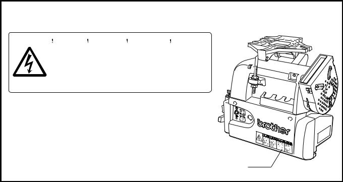
3. WARNING LABEL
The warning label shown below is affixed to the cover of the control box. Please follow the instructions on the label at all times when using the motor. If the label has been removed or is difficult to read, please contact your nearest Brother dealer.
|
|
|
|
|
|
|
|
|
|
|
|
|
|
|
|
|
|
|
|
|
|
Hazardous voltage |
Hochspannung |
Un voltage non adapt |
Un voltaje inadecuado |
||
|
will cause injury. |
verletzungsgefahr! |
provoque des blessures. |
puede provocar las |
||
|
Turn off main |
Bitte schalten sie den |
Eteindrel’interrupteur et |
heridas. |
||
|
Apagar el interruptor |
|||||
|
switch and wait 5 |
hauptschalter aus und |
attendre 5 minutes |
|||
|
minutes before |
warten sie 5 minuten, |
avantd’ ouvrir le capot |
principal y esperar 5 |
||
|
opening this cover. |
bevor sie diese |
|
minutos antes de abrir |
||
|
|
abdeckung ffnen. |
|
esta cubierta. |
||
|
|
|
|
|
|
|
Warning label
iii |
MD-602, 612 |
1. Outline
1.1 Features
•Thread trimming motor MD602/MD612 is a low-priced version of the MD601/611.
•Start tacking (2 to 9 stitches) and end tacking (2 to 9 stitches) are possible even without the operation panel (option).
•Voltage specifications for the single-phase 100V system, single-phase 200V system and 3-phase 200V system are available.
•The rated output is 400W.
•The motor torque has been greatly increased compared to the MD601/611.
1.2 Combination with Brother sewing machines
1. Single needle lockstitch machines (forward rotation)
B737, (B201) B791, B774, B722, B724, B748A, B798, B728, B772A, B778A, B781, B852, B853, B854, B883
2.Twin needle lockstitch machines (forward rotation)
B842, B872, B845, B875, B847, B848, B837, B877, B878
3.Overlock machine (reverse rotation)
(Note) The motor connections do not need to be changed to enable reverse rotation.
4. Post-type sewing machine (forward rotation)
P73, P81, C51
1.3 Options
•Operation panel F-20, F-40, F-100
•Material edge sensor II, material edge sensor IV, B sensor, bobbing thread detector
•Standing work pedal (variable speed pedal, 2-speed pedal)
1.4 Input/output
• Solenoid output: Four outputs (thread trimming, thread wiper, reverse run, presser foot lift) + one output for options
1.5 Miscellaneous
•Lamp terminal block and fuse mounted on control PCB.
•Only high-speeds are set with the head setting mode.
•Incompatible with magnetic synchronizer.
MD-602, 612 |
1 |
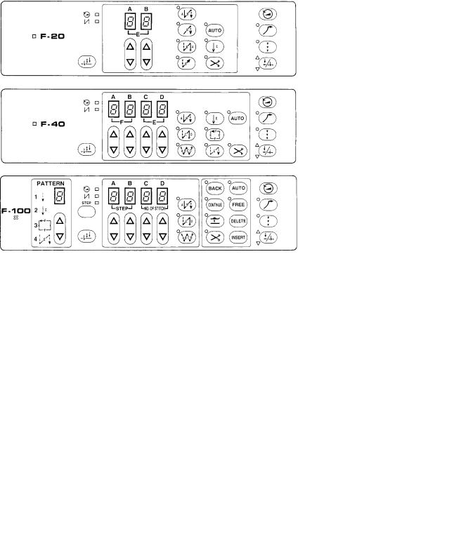
2. Operation panel and options
Attachable operation panel |
F-20 (X-20) |
|
F-40 (X-40) |
|
F-100 (X-100) |
Attachable options |
Standing work pedal |
|
Material edge sensor (Connect to S2 operation panel and use) |
(Note 1) A built-in type panel for B737 and an external type (twin needle, etc.) F-panels are available.
(Note 2) The X-panels can be used with the MD600 Series, but these panels do not have the stitching speed switch
[  ].
].
(Note 3) The E-panel for the MD800 series cannot be used with the MD600 Series.
Assembly cord for standing work
Standing treadle 40 variable speed #6
Standing treadle two speed
Operation panel
Sewing machine |
Installation |
Type |
Code no. of |
model |
type |
|
operation panel |
|
|
F-20 |
137-207-711-11 |
B737MK II |
built-in |
F-40 |
137-207-712-11 |
|
|
F-100 |
137-207-713-11 |
|
|
BF-20 |
137-207-811-11 |
B201 |
built-in |
BF-40 |
137-207-812-11 |
|
|
BF-100 |
137-207-813-11 |
Operation panel |
|
F-20 |
137-207-711-10 |
(without install |
attached |
F-40 |
137-207-712-10 |
plate) |
|
F-100 |
137-207-713-10 |
|
|
|
|
J80081-040 |
#8 |
J80380-040 |
|
|
J80630-001 |
Foot plug |
J02824-001 |
2 |
MD-602, 612 |
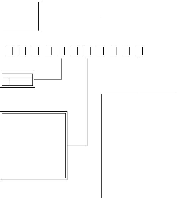
3. Model configuration
●Japanese / English;
Name Plate, Warning Label Instruction Manual
Panel type
|
BF panel |
F panel |
0 |
BF-0 |
F-0 |
1 |
None |
None |
2 |
BF-20 |
F-20 |
3 |
BF-40 |
F-40 |
4 |
BF-100 |
F-100 |
|
|
|
|
|
|
|
|
|
● C; With one forward and one |
||||||
|
|
|
|
|
|
|
|
|
|||||||
|
|
Panel |
Japanese/ |
Treadle |
|
back step |
|
|
|
||||||
|
|
type |
English |
type |
|
|
|
|
|||||||
|
|
|
D; With two forward and two |
||||||||||||
|
0 |
|
Japanese |
|
|
|
|||||||||
|
|
C |
|
back steps |
|
|
|
||||||||
|
|
External |
|
|
|
|
|
|
|
|
|
|
|
||
|
1 |
|
|
|
|
|
|
|
|
|
|
|
|||
|
|
|
|
|
|
|
|
|
|
|
|
|
|
||
|
|
(HB) |
English |
|
|
|
|
|
|
|
|
|
|
||
|
5 |
|
|
|
|
D |
|
|
|
Maximum |
|
|
|||
|
|
|
|
|
|
|
|
rotation speed |
|
|
|||||
|
|
|
|
|
|
|
|
|
|
|
|
|
|||
|
7 |
|
Japanese |
|
|
|
|
|
0 |
|
1000 rpm |
|
|
||
|
Built-in |
C |
|
|
|
1 |
|
2000 rpm |
|
|
|||||
|
|
|
|
|
|
|
|
|
|
|
|||||
|
|
|
|
|
|
|
|
|
|
|
|
|
|||
|
3 |
|
|
|
|
|
|
3 |
|
3000 rpm |
|
|
|||
|
|
|
|
|
|
|
|
|
|
|
|
||||
|
(BI) |
|
|
|
|
|
|
|
|
|
|
|
|
|
|
|
English |
|
|
|
|
|
4 |
|
3500 rpm |
|
|
||||
|
|
|
|
|
|
|
|
|
|
||||||
|
|
|
|
|
|
|
|
|
|
|
|||||
|
8 |
|
|
|
|
D |
|
|
|
5 |
|
4000 rpm |
|
|
|
|
|
|
|
|
|
|
|
|
|
|
6 |
|
4500 rpm |
|
|
|
|
|
|
|
|
|
|
||||||||
|
|
|
|
|
|
|
|
|
|
7 |
|
5000 rpm |
|
|
|
|
|
|
|
|
|
|
|
|
|
8 |
|
6000 rpm |
|
|
|
|
|
|
|
|
|
|
|
|
|
9 |
|
8000 rpm |
|
|
|
|
|
|
|
|
|
|
|
|
|
|
|
|
|
||
|
|
|
|
|
|
|
|
|
|
|
A |
|
2200 rpm |
|
|
|
|
|
|
|
|
|
|
|
|
|
B |
|
2400 rpm |
|
|
|
|
|
|
|
|
|
|
|
|
|
C |
|
2600 rpm |
|
|
|
|
|
|
|
|
|
|
|
|
|
D |
|
6500rpm |
|
|
|
|
|
|
|
|
|
|
|
|
|
|
|
|
|
|
|
|
|
|
|
|
|
|
|
|
|
|
|
|
|
|
1 |
3 |
7 |
6 |
0 |
2 |
7 |
3 |
3 |
5 |
5 |
Single/3-phase
0Single-phase
13-phase
Compatible head
|
Single needle |
|
Twin needle |
||
0 |
|
B774 |
E |
|
B842 |
1 |
|
B748A |
F |
|
B872 |
2 |
|
B798/728 |
G |
|
B845/875 |
3 |
|
B722 |
H |
|
B847 |
4 |
|
B724 |
J |
|
B837 |
5 |
|
B201 |
K |
|
B877 |
6 |
|
B791 |
L |
|
B878 |
7 |
|
B737 |
M |
|
P73/P81 |
8 |
|
B852/853/854 |
N |
|
C51 |
9 |
|
B883 |
P |
|
B848 |
A |
|
Overlock |
|
|
|
B |
|
B772A |
|
|
|
C |
|
B778A |
|
|
|
D |
|
B781 |
|
|
|
For single-phase
|
|
Voltage |
Switch |
Destination |
|
0 |
240V |
SAA compatible part |
Australia |
|
1 |
110V |
Standard part |
General |
|
2 |
110V |
With OCR |
USA |
|
3 |
110V |
SJT |
Canada |
|
4 |
230V |
None |
Europe |
|
5 |
220V |
Standard part |
General |
|
6 |
230V |
Standard part |
Greece |
|
7 |
230V |
Standard part |
General |
|
8 |
230V |
SAA compatible part |
New Zealand |
|
9 |
100V |
Domestic specifications |
Japan |
|
A |
240V |
Standard part |
General |
|
B |
110V |
SJT + OCR |
Canada |
|
C |
220V |
With OCR |
General |
|
D |
220V |
SJT + OCR |
Canada |
|
E |
220V |
FOR B883 |
General |
For 3-phase |
|
|
||
|
|
|
|
|
|
|
Voltage |
Switch |
Destination |
|
0 |
200V |
Domestic specifications |
Japan |
|
1 |
220V |
Standard part |
|
|
2 |
220V |
With OCR |
USA |
|
3 |
220V |
With SJT |
Canada |
|
B |
220V |
With SJT & OCR |
Canada |
MD-602, 612 |
3 |
4. Explanation of the name plate
Control box name plate
MD-6*2*-* CONTROL BOX TYPE B qwert
NO. yuio!0!1!2!3!4
Motor name plate
MD-60A
AC SERVO MOTOR NO. yuio!0!1!2!3!4
y |
production |
|
date |
A |
January |
B |
February |
C |
March |
D |
April |
E |
May |
F |
June |
G |
July |
H |
August |
J |
September |
K |
October |
L |
November |
M |
December |
|
|
|
|
|
|
|
|
|
|
|
|
|
|
|
|
|
|
|
|
|
|
|
|
|
|
|
|
|
|
|
|
|
****** PHASE |
|
|
|
|
|
|
|
|
|
|
|
|
|
|
|
|
|
|
|
|
|
|||||||
|
|
OUT PUT 400W |
|
|
|
|
|
|
|
|
|
|
|
|
|
|
|
|
|
|
|
|
||||||||
|
|
VOLTS |
********* |
|
|
|
|
|
|
|
|
|
|
|
|
|
|
|
|
|
|
|
|
|
|
|
||||
|
|
|
|
|
|
|
|
|
|
|
|
|
|
|
|
|
|
|
|
|
|
|
|
|
||||||
|
|
HERTZ |
50/60 |
|
|
|
|
|
|
|
|
|
|
|
|
|
|
|
|
|
|
|
|
|
|
|
||||
|
|
|
|
FOR MD-60A |
|
|
|
|
|
|
|
|
|
|
|
|
|
|
|
|
|
|
|
|
||||||
|
|
|
|
|
|
MADE IN JAPAN |
|
|
|
|
|
|
|
|
|
|
|
|
|
|
|
|
|
|
|
|
||||
|
|
BROTHER INDUSTRIES, LTD. |
|
|
|
|
|
|
|
|
|
|
|
|
display |
|
|
|||||||||||||
|
|
|
phase |
|
voltage |
|
|
|
|
|
|
|
|
|
|
|
||||||||||||||
|
|
|
|
|
|
|
|
|
|
|
|
|
|
|
|
|
|
|
|
|
|
|
|
|||||||
|
|
|
|
|
|
|
|
|
|
|
|
|
|
phase |
|
|
voltage |
|
|
|||||||||||
|
|
|
|
|
|
|
|
|
|
|
|
|
|
|
|
|
|
|
|
|
|
|
|
|
||||||
|
|
|
|
|
|
|
|
|
|
|
|
|
|
|
|
|
|
|
|
|
|
|
|
|
|
|
||||
|
|
|
|
|
|
|
|
|
|
|
|
single |
|
110V |
|
SINGLE |
|
|
|
|
|
|
110 |
|
||||||
|
|
|
|
|
|
|
|
|
|
|
|
single |
|
220V |
|
SINGLE |
|
|
230 |
|
240 |
|
||||||||
|
|
|
|
|
|
|
|
|
|
|
|
|
|
|
220 |
|||||||||||||||
OUT PUT |
|
400W |
|
single |
|
230V |
|
SINGLE |
220 |
|
|
|
240 |
|
||||||||||||||||
|
|
|
|
|
|
230 |
|
|||||||||||||||||||||||
R.P.M. |
3500 |
|
|
|
single |
|
230V CE |
|
SINGLE |
|
|
|
|
|
|
230 |
|
|||||||||||||
|
|
|
|
|
|
|
|
|
|
|
|
|||||||||||||||||||
SUPPLIED FROM CONTROL BOX |
|
|
|
|
|
|
|
|
|
|
||||||||||||||||||||
|
single |
|
240V |
|
SINGLE |
220 |
230 |
|
|
|
||||||||||||||||||||
MD-602/612 |
|
|
|
|
|
|
|
|
|
240 |
|
|||||||||||||||||||
|
|
|
|
|
|
MADE IN JAPAN |
|
three |
|
220V |
|
THREE |
|
|
|
|
|
|
220 |
|
||||||||||
|
|
|
BROTHER INDUSTRIES, LTD. |
|
|
|
|
|
|
|
|
|
|
|||||||||||||||||
|
|
|
|
|
|
|
|
|
|
|
|
|
|
|
|
|
|
|
|
|
|
|
|
|
|
|
|
|
||
|
|
|
|
|
|
|
|
|
|
|
|
|
|
|
|
|
|
|
|
|
|
|
|
|
|
|
|
|
|
|
|
|
|
|
|
|
|
|
|
|
|
|
q |
|
Treadle type |
|
|
|
e |
|
|
maximum |
|||||||||
|
|
|
|
|
|
|
|
|
|
|
|
C |
|
One forward and |
|
|
|
speed (rpm) |
||||||||||||
|
|
ui |
|
year (2 digits) |
|
|
|
|
one back step |
|
|
0 |
|
1000 |
|
|||||||||||||||
|
|
|
|
|
|
|
|
|
|
|
|
D |
|
Two forward and |
|
|
1 |
|
2000 |
|
||||||||||
|
|
|
|
|
|
|
|
|
|
|
|
|
|
|
||||||||||||||||
|
|
|
|
|
|
|
|
|
|
|
|
|
|
two back step |
|
|
2 |
|
2500 |
|
||||||||||
|
|
o |
|
|
factory |
|
|
|
|
|
|
|
|
|
|
|
|
|
|
|
|
|||||||||
|
|
|
|
|
|
|
|
|
|
|
|
|
|
|
|
|
|
|
||||||||||||
|
|
|
|
|
|
|
|
|
|
|
|
|
|
|
|
|
|
3 |
|
3000 |
|
|||||||||
|
|
|
|
|
|
|
|
|
|
|
|
|
|
|
|
|
|
|
|
|
|
|
|
|
|
|||||
|
9 |
|
|
|
Kariya |
|
|
|
|
|
|
|
|
|
|
|
|
|
|
|
||||||||||
|
|
|
|
|
|
w |
|
|
Pulley size |
|
|
|
4 |
|
3500 |
|
||||||||||||||
|
|
|
|
|
|
|
|
|
|
|
|
|
|
|
|
|
|
|
||||||||||||
|
|
|
|
|
|
|
|
|
|
|
|
|
|
|
|
|
|
|||||||||||||
|
|
|
|
|
|
|
|
|
|
|
|
|
|
|
|
|
|
|
|
|
|
|
|
|
|
|||||
|
|
|
|
|
|
|
|
|
|
|
3 |
|
|
|
φ |
90 |
|
|
|
|
|
5 |
|
4000 |
|
|||||
|
|
|
|
|
|
|
|
4 |
|
|
|
φ |
105 |
|
|
|
|
|
|
|
|
|
|
|
|
|||||
|
!0 |
|
modification No. |
|
|
|
|
|
|
6 |
|
4500 |
|
|||||||||||||||||
|
|
|
|
|
|
|
|
|
|
|
|
|
|
|
|
|
|
|
|
|
|
|
|
7 |
|
5000 |
|
|||
|
|
|
|
|
|
|
|
|
|
|
|
t |
|
standard |
|
|
|
|
|
8 |
|
6000 |
|
|||||||
|
!1!2!3!4 |
serial No. |
|
|
|
|
|
|
|
|||||||||||||||||||||
|
|
0 |
|
None |
|
|
|
|
|
|
|
9 |
|
8000 |
|
|||||||||||||||
|
|
|
|
|
|
|
|
|
|
|
|
|
|
|
|
|
|
|
|
|
||||||||||
|
|
|
|
|
|
|
|
|
|
|
|
|
|
|
|
|
|
|
||||||||||||
|
|
|
|
|
|
|
|
|
|
|
|
A |
|
Australia |
|
|
|
|
|
A |
|
2200 |
|
|||||||
|
|
|
|
|
|
|
|
|
|
|
|
E |
|
CE |
|
|
|
|
|
|
|
|
|
B |
|
2400 |
|
|||
|
|
|
|
|
|
|
|
|
|
|
|
|
|
|
|
|
|
|
|
|
|
|
|
C |
|
2600 |
|
|||
|
|
|
|
|
|
|
|
|
|
|
|
|
|
|
|
|
|
|
|
|
|
|
|
D |
|
6500 |
|
|||
|
|
|
|
|
|
|
|
|
|
|
|
|
|
|
|
|
|
|
|
|
|
|
|
|
|
|
|
|
|
|
r |
Machine Head |
Model No. |
r |
Machine Head |
Model No. |
* |
phase |
(Single needle) |
(Twin needle) |
0 |
single |
||||
0 |
B774 |
MD-6*2-1 |
E |
B842 |
MD-6*2-1 |
1 |
three |
1 |
B748A |
MD-6*2-1 |
F |
B872 |
MD-6*2-1 |
|
|
2 |
B798/728 |
MD-6*2-1 |
G |
B845/875 |
MD-6*2-1 |
|
|
3 |
B722 |
MD-6*2-1 |
E |
B847 |
MD-6*2-1 |
|
|
4 |
B724 |
MD-6*2-1 |
J |
B837 |
MD-6*2-1 |
|
|
5 |
B201 (B755) |
MD-6*2-1 |
K |
B877 |
MD-6*2-15 |
|
|
6 |
B791 |
MD-6*2-1 |
L |
B878 |
MD-6*2-15 |
|
|
7 |
B737 |
MD-6*2-1 |
M |
P73/P81 |
MD-6*2-9 |
|
|
8 |
B852/853/854 |
MD-6*2-1 |
N |
C51 |
MD-6*2-9 |
|
|
9 |
B883 |
MD-6*2-5 |
P |
B848 |
MD-6*2-1 |
|
|
A |
OVERLOCK |
MD-6*2R-1 |
|
|
|
|
|
B |
B772A |
MD-6*2-1 |
|
|
|
|
|
C |
B778A |
MD-6*2-1 |
|
|
|
|
|
D |
B781 |
MD-6*2-1 |
|
|
|
|
|
4 |
|
|
|
MD-602, 612 |
|
|
|
5. Installation
 CAUTION
Do not use the motor near sources of strong electrical interference. If the motor is installed in a location which is close to sources of strong electrical interference such as high-frequency welders, it may cause problems with correct operation of the sewing machine.
Disconnect the power cord plug from the wall outlet before installing the motor.
The motor and control box weigh approximately 13 kg. Take care not to drop them on your feet when installing them to the work table.
Be sure to tighten the nuts securely.
If they are not tightened properly, it could cause the sewing machine to vibrate or shift its position while sewing.
5.1 Installing the motor to the work table
w q
e r t
y
3-φ 8.5
q
e
u
66
57 159
Hazardous voltage |
Hochspannung |
Un voltage non adapté |
Un voltaje inadecuado |
will cause injury. |
verletzungsgefahr! |
provoque des blessures. |
puede provocar las |
Turn off main |
Bitte schalten sie den |
Eteindrel'interrupteur et |
heridas. |
switch and wait 5 |
hauptschalter aus und |
attendre 5 minutes |
Apagar el interruptor |
minutes before |
warten sie 5 minuten, |
avantd' ouvrir le capot |
principal y esperar 5 |
opening this cover. |
bevor sie diese |
|
minutos antes de abrir |
|
abdeckung öffnen. |
|
esta cubierta. |
|
|
|
|
1.Insert the bolts w into the holes in the work table q and then secure the motor u to the work table q by tightening the motor mounting brackets e to the work table q with the flat washers r, spring washers t and nuts y as shown in the illustration.
2.The positions of the work table q holes are shown in the illustration.
5.2 Attaching the belt
e
Tilt back
q
10 – 14 mm of deflection
r
w
1.Tilt back the machine head and place the belt q onto the motor pulley w and the machine pulley e.
2.Turn the two nuts r to adjust the deflection in the V- belt q when the center of the belt is pushed.
The recommended values are:
1.For single-needle sewing machines and overlock machines, the deflection should be 10 – 14 mm when the belt is pushed with a force of 5 N (500 g).
2.For twin needle sewing machines, the deflection should be 10 – 20 mm when the belt is pushed with
a force of 10 N (1 kg).
Note:
While using the sewing machine, the belt will conform to the pulley and cause the belt tension to loosen. If the belt tension is too loose, the following problems can occur.
1.The stopping position may shift.
2.An abnormal noise may be heard due to belt slippage.
3.The belt may become too loose and contact the cover.
4.When sewing heavy materials, the belt may slip on the pulley and the sewing machine may stop.
MD-602, 612 |
5 |
5.3 Installing the belt cover
q |
1. |
Secure the belt cover q to the motor e with the two |
|
screws w as shown in the illustration. At this time, po- |
|
|
|
sition the belt cover q so that it does not touch the belt. |
e |
2. |
A belt casting prevention guide and finger guide are |
|
|
provided on the belt cover. Refer to “5.5 Adjusting the |
|
|
belt cover safety mechanisms” on this page. |
w
w
5.4 Connecting the connecting rod
r |
• Pass the connecting rod joint q through hole A in the |
|
e |
treadle lever w, and tighten it with the spring washer |
|
e and nut r. |
||
|
||
|
• Adjust the position of the machine treadle plate so that |
|
|
the connecting rod is perpendicular to the treadle plate. |
|
q |
Note: |
|
The treadle pressure is adjusted to the position of hole |
||
w |
A at the time of shipment from the factory. Refer to “6. |
|
A |
Adjusting the treadle unit”. |
|
|
5.5 Adjusting the belt cover safety mechanisms
Forward rotation
|
w |
|
e |
q |
|
r |
|
|
Mark for 105 mm- |
|
|
diameter pulley |
|
|
Mark for 90 mm- |
|
|
diameter pulley |
|
|
Mark for 80 mm- |
Mark for 80 mm- |
|
diameter pulley Mark for |
||
diameter pulley |
||
90 mm- |
Mark for 105 mm- |
|
diameter |
diameter pulley |
|
pulley |
|
Reverse rotation (Overlock machines)
e r
5.5.1Adjusting the belt casting prevention guide
1.Loosen the screw q.
2.A mark showing the pulley size is stamped on the belt cover. (The available inner diameters are 90 mm, 105
mm and 80 mm.)
Adjust the position of the belt casting prevention cover w in accordance with the pulley size. Align the projection position with the mark. (For 80 mm diameter pulleys, install the belt casting prevention cover w in the reverse direction.)
3.After adjusting, tighten the screw q.
Note:
This safety guide will prevent the belt from coming off even when the machine head is tilted back.
5.5.2Adjusting the finger guard
1.Loosen the screw e.
2.Install the finger guard so that it is on the belt winding side.
3.A mark showing the pulley size is stamped on the belt cover. (The available inner diameters are 80 mm, 90 mm and 105 mm.)
Adjust the position of the finger guard r in accordance with the pulley size. Align the center of the screw with the mark.
4.After adjusting, tighten the screw e.
Note:
The finger guard is a safety mechanism that prevents
fingers from being caught in the belt.
Change the position of the finger guard r to match the direction of rotation of the motor pulley.
6 |
MD-602, 612 |

5.6 Connecting the cords
CAUTION
Turn off the power switch and wait for the power indicator on the panel display to turn off before connecting and disconnecting any of the connectors.
Turn off the power switch before inserting or removing the AC power cord plug.
Be sure to connect the power supply to a secure ground. If the ground is not securely connected, electric shocks may result.
5.6.1 Connecting the power cord, power switch and ground cord
|
Power switch |
Ground symbol |
Power cord |
|
Mounting bracket grounding screw
Ground
minutes before |
warten sie 5 minuten, |
avantd' ouvrir le capot |
principal y esperar 5 |
Green/yellow |
Hazardous voltage |
Hochspannung |
Un voltage non adapté |
Un voltaje inadecuado |
|
will cause injury. |
verletzungsgefahr! |
provoque des blessures. |
puede provocar las |
|
Turn off main |
Bitte schalten sie den |
Eteindrel'interrupteur et |
heridas. |
|
switch and wait 5 |
hauptschalter aus und |
attendre 5 minutes |
Apagar el interruptor |
|
opening this cover. |
bevor sie diese |
|
minutos antes de abrir |
|
|
abdeckung öffnen. |
|
esta cubierta. |
|
Sewing machine oil pan |
Ground cord |
5.6.2 Connecting the sewing machine and control box
12-pin plug |
6-pin plug |
q
|
|
|
|
|
|
|
|
|
|
|
|
|
|
|
|
|
|
|
|
Hazardous voltage |
Hochspannung |
Un voltage non adapté |
Un voltaje inadecuado |
|
|
|
|
|
|
|
|
|
|
|
|
|
|
|
will cause injury. |
verletzungsgefahr! |
provoque des blessures. |
puede provocar las |
|
|
|
|
|
|
|
|
|
|
|
|
|
|
|
Turn off main |
Bitte schalten sie den |
Eteindrel'interrupteur et |
heridas. |
|
|
|
|
|
|
|
|
|
|
|
|
|
|
|
switch and wait 5 |
hauptschalter aus und |
attendre 5 minutes |
Apagar el interruptor |
|
|
|
|
|
|
|
|
|
|
|
|
|
|
|
minutes before |
warten sie 5 minuten, |
avantd' ouvrir le capot |
principal y esperar 5 |
|
|
|
|
|
|
|
|
|
|
|
|
|
|
|
opening this cover. |
bevor sie diese |
|
minutos antes de abrir |
|
|
|
|
|
|
|
|
|
|
|
|
|
|
|
|
abdeckung öffnen. |
|
esta cubierta. |
|
|
|
|
|
|
|
|
|
|
|
|
|
|
|
|
|
|
|
|
|
|
|
|
|
|
|
|
|
|
|
|
|
|
|
|
|
|
|
|
|
|
|
|
|
|
|
|
|
|
|
|
|
|
|
|
|
|
|
|
|
|
|
|
|
|
|
|
|
|
|
|
|
|
|
|
|
|
|
|
|
|
|
|
|
|
|
|
|
|
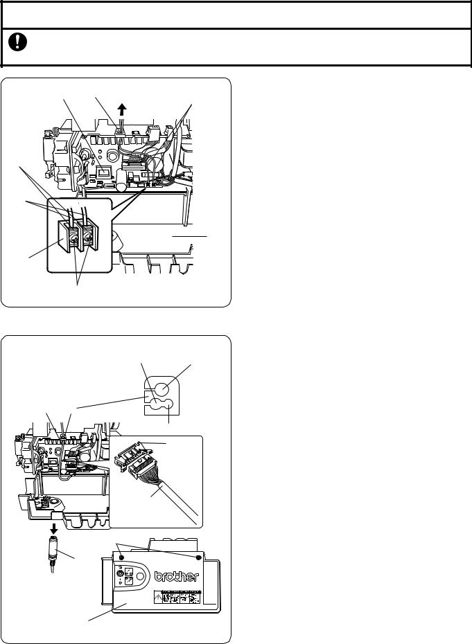
w
e
• Loosen the two screws q, and then gently pull the |
e Synchronizer cord |
|
cover w toward you to open it. |
||
|
||
• Connect the 12-pin plug and the 6-pin plug. |
|
|
• Close the cover w (be careful not to clamp the cord) |
|
|
and tighten the two screws q. |
|
|
• Connect the synchronizer cord e. |
|
MD-602, 612 |
7 |
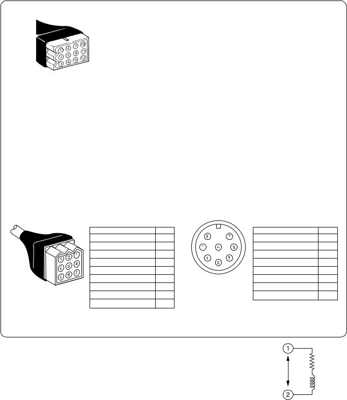
For machine solenoid |
For presser foot lifter |
12-pin plug
6-pin plug
• 12-pin plug terminal |
|
|
• 6-pin plug terminal |
|
12-pin plug |
No. |
|
6-pin plug |
No. |
Thread trimming solenoid |
r·t |
|
Presser lifter solenoid |
q·r |
Thread wiping solenoid |
u·i |
|
40 V power supply |
e |
Quick reverse solenoid |
!0·!1 |
|
Knee switch |
w·t |
Quick reverse switch |
o·!2 |
|
Ground |
y |
Option output |
q·w |
|
|
|
Ground |
e |
|
|
|
Spare |
y |
|
|
|
For standing pedal (option) |
|
|
For synchronizer |
|
9-pin plug |
• 9-pin plug terminal |
|
• 8-pin plug terminal |
|
|
9-pin plug |
No. |
8-pin plug |
No. |
|
High-speed switch |
w |
Ground |
q |
|
Low-speed switch |
y |
+5 V |
w |
|
Thread trimming switch |
e |
Needle down signal |
e |
|
Presser foot lift switch |
u |
0 V |
r |
|
+8 V |
q |
NONP |
t |
|
VSP |
i |
Needle up signal |
y |
|
0 V |
r |
Encoder |
u |
|
Ground |
o |
Ground |
i |
|
Spare |
t |
|
|
Note:
The puller output is output from the option output during machine operation with the settings made at shipment from the factory.
Note the following points when connecting to the option output terminals.
a.Connect a solenoid or air valve with a resistance of 10 Ω or greater.
b.The voltage between the terminals should be equivalent to 40 V DC. When connecting an air valve, connect a resistor in series so that the rated voltage is obtained.
c.Never short circuit the output terminals.
Note:
Resistor
Approx.
40 V
Air valve
If using an automatic presser foot lifter, set the DIP switch SW1-3 on the circuit board to ON. (Refer to “7.5.2 Other DIP switch functions”.)
8 |
MD-602, 612 |
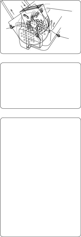
5.7 Installing the head lamp
CAUTION
Use a lamp which is rated at 6 V AC and 20 W or less as the head lamp.
If a lamp with a higher rating than this is used, it could cause the lamp wires and the transformer to overheat and burn out.
|
|
|
|
1. |
Open the control box cover q. |
CPU |
y |
Lamp |
Lamp cords |
2. |
Loosen the screws e of the terminal block w, insert the |
t |
|
lamp cords t into the clamps r as far as they will go, |
|||
|
|
|
|||
|
|
|
|
|
and then tighten the screws e. |
|
|
|
|
|
Note: |
|
|
|
|
|
Do not tighten the screws e too tightly, as this may |
|
|
|
|
|
damage the terminal block w. |
|
|
|
|
3. |
Pass the lamp cords t through the rubber plug y. |
r |
|
|
|
|
Refer to the illustration of the rubber plug y in “5.8 |
|
|
|
|
Connecting the external operation panel” at below-left |
|
|
|
|
|
|
on this page at this time. |
|
|
|
|
4. |
Close the control box cover q. |
t
q
w
e
5.8 Connecting the external operation panel
|
For external |
For option |
operation panel |
u y
For lamp cords
r
t
w
q
1.The F-20, F-40 and F-100 operation panels can be used.
2.Disconnect the synchronizer cord q.
3.Loosen the screw w, and then gently pull the cover e toward you to open it.
4.After opening the pawl of the circuit board connector r, align the ▼ mark on the operation panel connector t with the ▼ mark on the circuit board connector r, and securely insert operation panel connector t until the pawl locks.
5.Fit the rubber plug y onto the operation panel cord u as shown in the illustration, and then install the control box while being careful not to damage the cord u. (Break the membrane of the rubber plug y.)
6.Close the cover e and secure it with the screw w. Be careful not to clamp any of the cords with the cover.
7.Connect the synchronizer cord q.
e
Note:
When an external operation panel is installed, the backtacking function of the control circuit board will be disabled, so use the external operation panel to carry out backtacking.
MD-602, 612 |
9 |

6. Adjusting the treadle unit
6.1 Operating the treadle
•There are two types of treadles, one with one forward and one rear stage and one with two forward and two rear stages. These are provided according to the destination of the machine.
6.1.1For treadles with one forward and one rear stage
CAUTION
Take your foot off the treadle before turning on the power switch.
Neutral
Low speed
High speed
q
w
e
r Thread trimming
1.The treadle is at the neutral position q when the treadle is not pressed.
2.When the treadle is gently depressed to position w, low-speed sewing is carried out. If it is then depressed as far as e, high-speed sewing is carried out.
3.When the treadle is pressed forward and then back to the neutral position q, the needle will stop below the needle plate (when needle down stop mode has been set).
4.When the treadle is depressed backwards to position r (or when the treadle is pressed backward to position r and is then returned to neutral position q), the thread trimmer operates, and then the needle will be raised and stop above the needle plate.
5.If using with the synchronizer cord disconnected
•When the treadle is pressed forward and then back to the neutral position q, the machine will stop regardless of the needle position.
•Thread trimming will not be carried out even if the treadle is pressed backed to position r. (The sewing machine does not operate.)
6. If an automatic presser foot lifter is being used
•The presser foot will rise when the treadle is pressed backwards. If the knee switch is pressed, the pressure foot will not raise with the treadle operation, so raise and lower the presser foot with the knee switch.
•When the treadle is pressed backwards and the thread is trimmed, the sewing machine will stop, and the presser
foot will rise. To lower the presser foot, press the treadle backwards and then return it to the neutral position q. The presser foot can also be lowered using the knee switch. If the treadle is pressed forward, the sewing machine will operate after the presser foot lowers.
Note:
The presser foot can be raised and lowered by returning the treadle only from when the power switch is turned on to when the knee switch is operated.
10 |
MD-602, 612 |
6.1.2For treadles with two forward and two rear stages
CAUTION
Take your foot off the treadle before turning on the power switch.
Neutral
Presser foot lowered
Low speed
High speed
q
y
w
e
t Presser foot raised
r Thread trimming
1.The treadle is at the neutral position q when the treadle is not pressed.
2.When the treadle is gently depressed to position w, low-speed sewing is carried out. If it is then depressed as far as e, high-speed sewing is carried out.
3.When the treadle is pressed forward and then back to the neutral position q, the needle will stop below the needle plate (when needle down stop mode has been set).
4.When the treadle is depressed backwards to position r (or when the treadle is pressed backward to position r and is then returned to neutral position q), the thread trimmer operates, and then the needle will be raised and stop above the needle plate.
5.If using with the synchronizer cord disconnected
•When the needle is pressed forward and then back to the neutral position q, the machine will stop regardless of the needle position.
•Thread trimming will not be carried out even if the treadle is pressed backed to position r. (The sewing machine does not operate.)
6. If an automatic presser foot lifter is being used
•The presser foot will rise when the treadle is gently pressed back to the backward position t.
•The presser foot will lower when the treadle is returned to the neutral position q.
•The presser foot will lower if the treadle is gently pressed to the position y while the presser foot is raised.
MD-602, 612 |
11 |
6.2 Adjusting the treadle
CAUTION
Turn off the power switch before starting work, otherwise the motor may operate, which could result in injury.
r
e q
w
a b c
Fig A |
Fig B |
t y
6.2.1Adjusting the treadle pressure
•If the machine starts running at a low speed when your foot is simply resting on the treadle, or if the treadle pressure is too weak, adjust the position (a to c) at which the treadle spring q is hooked onto the treadle lever w.
Note:
The treadle pressure will increase from position a to position c.
6.2.2Adjusting the treadle return pressure
•Loosen the nut e and turn the bolt r. The treadle return pressure becomes heavier as the bolt r is tightened, and becomes lighter as the bolt r is loosened.
6.2.3Adjusting the treadle stroke
•Remove the nut t, and then move the connecting rod joint y from the position in figure A to the position in figure B. The treadle stroke will increase by approx. 1.25 times.
Note:
This adjustment will also affect the treadle pressure and the treadle return pressure, so these settings should be readjusted if necessary.
q |
|
|
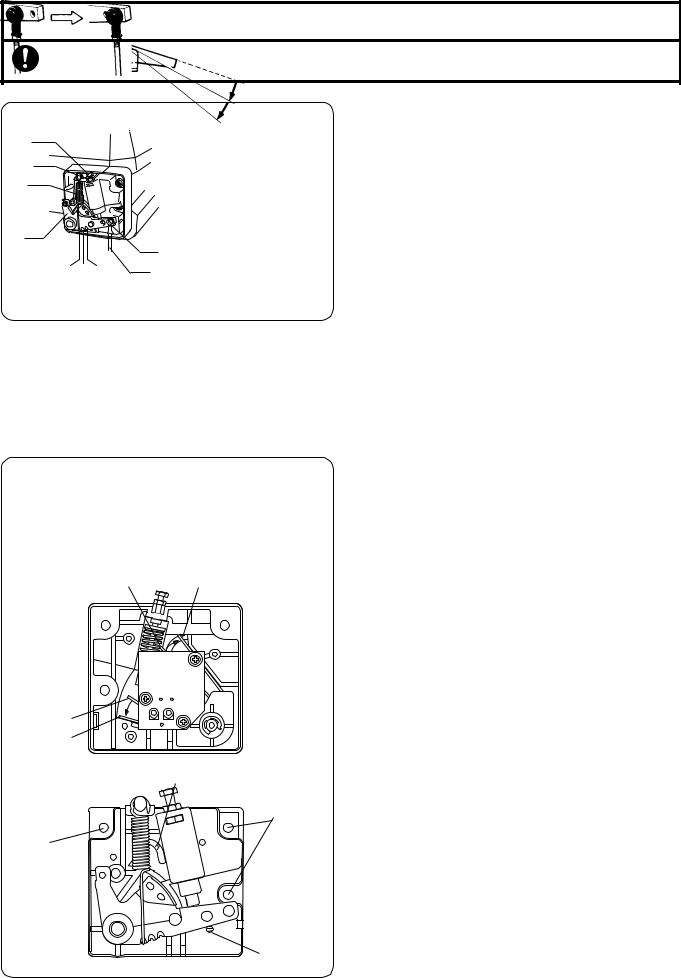
6.3 When using the automatic presser foot lifter |
||
|
|
|
device |
||
w |
|
|
|
||
|
|
|
|
||
|
|
|
1. |
When the treadle is depressed to position r, the |
|
|
|
|
|
presser foot is raised. |
|
|
|
|
2. |
If you would like the treadle pressure to be lighter when |
|
|
|
|
|
it is depressed forward from the 2nd step to the 1st |
|
|
|
|
|
step, change the position of the spring from F to E. |
|
Treadle unit |
C |
|
r |
If you would like the pedal return to be from the 2nd |
|
D |
step to the 1st step at this time, change the spring po- |
||||
|
|||||
|
|
|
• |
sition from C to D. |
|
|
|
|
When changing the spring positions from F to E and |
||
from C to D, you must remove the three screws q of the treadle unit and disconnect the treadle unit from the control box before changing the spring positions.
F
E
A
q
q
B
12 |
MD-602, 612 |
7. Using the control box
 CAUTION
Confirm that the power supply matches the motor and the control box specifications before turning on the power switch. The motor, control box or sewing machine could be damaged if the supply voltage is too high.
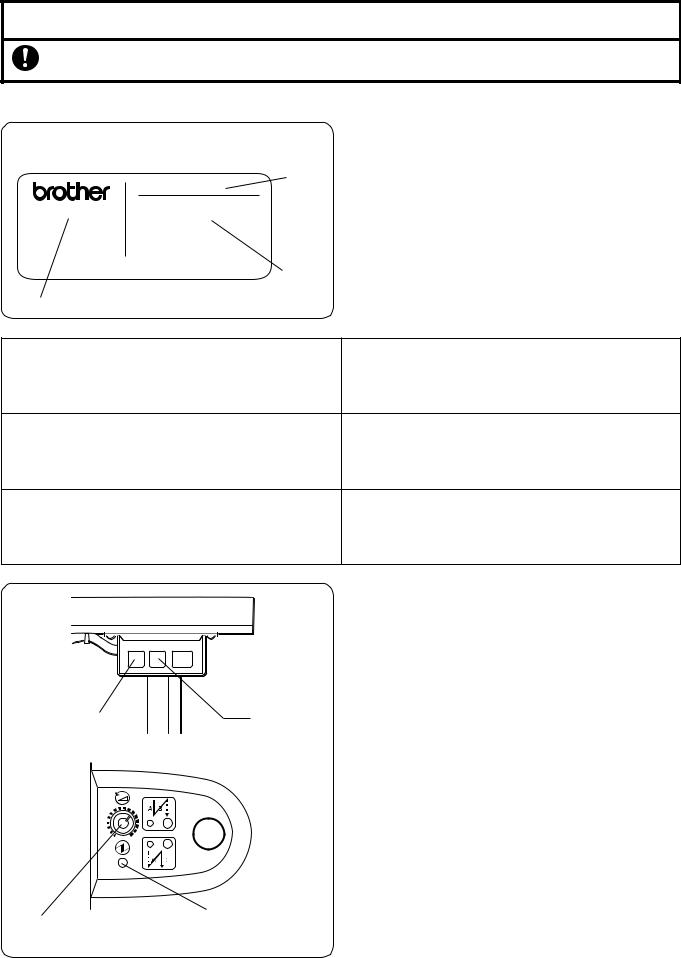
7.1 Before turning on the power switch
Control box rating plate (Example: Single-phase 220 V specifications)
MD-602-1
C O N T R O L B O X
T Y P E B C 4 6 7 0
N O . B 0 1 9 A 1 1 0 1
q Model
S I N G L E P H A S E
O U T P U T |
4 0 0 |
W |
||
V O LT S |
|
|
2 4 0 |
|
2 2 0 |
2 3 0 |
|||
H E R T Z |
|
5 |
0 / |
6 0 |
F O R M D - 6 0 A
MADE IN JAPAN BROTHER INDUSTRIES, LTD.
w
Power supply phase
e
Power supply voltage
•Check the power supply and the control box specifications.
1. Model q
MD-602 (for single-phase power supply) MD-612 (for three-phase power supply)
The model should match the power supply phase w.
2.The power supply voltage e indicated is an AC voltage.
3.The power supply frequency can be either 50 Hz or 60 Hz.
1. Are all connectors connected correctly? |
Refer to “5.6 Connecting the cords”. |
|
• |
Synchronizer connector |
|
• |
Sewing machine connector |
|
• |
Ground cord |
|
2.Is the sewing machine cord touching the V-belt? Is the belt tension correct?
Refer to “5.1 Installing the motor to the work table” and “5.2 Attaching the belt”.
3.Does the sewing machine operate when turned gently by hand?
7.2 Power switch and power indicator
• When the power ON switch q is pressed, the power
|
|
|
|
|
|
|
|
|
indicator (green) e lights and the power turns on. |
|
|
|
|
|
|
|
|
|
• When the power OFF switch w is pressed, the power |
|
|
|
|
|
|
|
|
|
indicator (green) e turns off and the power switches |
|
|
|
|
|
|
|
|
|
off. |
|
|
|
|
|
|
|
|
|
7.3 Setting the sewing speed |
w |
|
|
|
|
q |
• Turn the speed adjustment knob r on the front of the |
|||
|
|
|
|
|
|
|
|
|
control box clockwise to increase the sewing machine |
|
|
|
|
|
|
|
|
|
speed (the speed corresponding to the treadle depres- |
|
|
|
|
|
|
|
|
|
sion amount), and turn it counterclockwise to reduce |
|
|
|
|
|
|
|
|
|
the speed. |
|
|
|
|
|
|
|
|
|
• The maximum sewing speed that can be set is the sew- |
|
|
|
|
|
|
|
|
|
ing speed which is determined by DIP switch settings. |
|
|
|
|
|
|
|
|
|
Refer to “7.5.2.1 DIP switch 1 functions”. The minimum |
|
|
|
|
|
|
|
|
|
|
|
|
|
|
|
|
|
|
|
|
|
|
|
|
|
|
|
|
|
sewing speed is the sewing speed when the treadle is |
|
|
|
|
|
|
|
|
|
at the low-speed sewing position. |
|
|
|
|
|
|
|
|
|
|
|
|
|
|
|
|
|
|
|
|
e Power indicator
r Speed adjustment knob
MD-602, 612 |
13 |
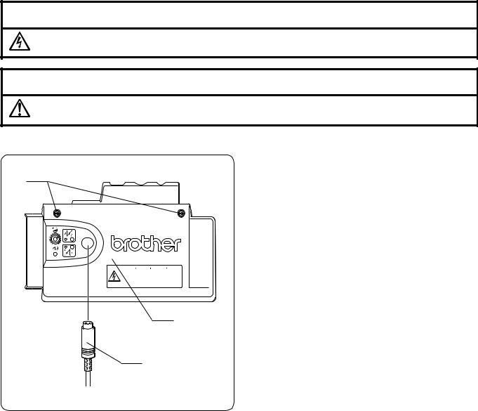
7.4 Control box DIP switch setting procedure
WARNING
Wait at least 5 minutes after turning off the power switch before opening the cover of the control box. Touching areas where high voltages are present can result in severe injury.
CAUTION
Do not clamp the cords inside the control box when closing the control box cover.
•Make sure that the DIP switches are set correctly, otherwise incorrect operation may result.
•Disconnect the synchronizer cord q.
•Loosen the two screws w, and then gently pull the
w |
cover e toward you to open it. |
|
• Set the DIP switches. |
||
|
Refer to the tables for details of DIP switch functions.
• Close the cover e (be careful not to clamp the cord) and tighten the two screws w.
• Connect the synchronizer cord q.
|
|
|
|
|
|
|
|
|
|
|
|
|
|
|
|
|
|
|
|
|
|
|
|
|
|
|
|
|
|
|
|
|
|
|
|
|
|
|
|
|
|
|
|
|
|
|
|
|
|
Hazardous voltage |
Hochspannung |
Un voltage non adapté |
Un voltaje inadecuado |
|
|
|
|
|
will cause injury. |
verletzungsgefahr! |
provoque des blessures. |
puede provocar las |
|
|
|
|
|
Turn off main |
Bitte schalten sie den |
Eteindrel'interrupteur et |
heridas. |
|
|
|
|
|
switch and wait 5 |
hauptschalter aus und |
attendre 5 minutes |
Apagar el interruptor |
|
|
|
|
|
minutes before |
warten sie 5 minuten, |
avantd' ouvrir le capot |
principal y esperar 5 |
|
|
|
|
|
opening this cover. |
bevor sie diese |
|
minutos antes de abrir |
|
|
|
|
|
|
abdeckung öffnen. |
|
esta cubierta. |
e
q
14 |
MD-602, 612 |
7.5 Description of functions
• The control panel is provided with the following functions.
|
· · · Can be used |
|
|
|
|
· · · Cannot be used |
|
|
|
|
|
|
|
|
Function |
No panel |
F-20 |
F-40 |
F-100 |
|
|
|
|
|
Maximum sewing speed setting |
|
|
|
|
|
|
|
|
|
Start backtacking speed setting |
|
|
|
|
|
|
|
|
|
Needle stop position |
|
|
|
|
|
|
|
|
|
Automatic thread trimming (thread trimming after Fixed stitch sewing) |
|
|
|
|
|
|
|
|
|
Slow start |
|
|
|
|
|
|
|
|
|
Correction sewing |
|
|
|
|
|
|
|
|
|
Highest needle position stop |
|
|
|
|
|
|
|
|
|
Start backtacking using control box (N) (2 – 9 stitches) |
|
|
|
|
|
|
|
|
|
End backtacking using control box (N) (2 – 9 stitches) |
|
|
|
|
|
|
|
|
|
Start backtacking using panel (N) (0 – 9 stitches) |
|
|
|
|
|
|
|
|
|
End backtacking using panel (N) (0 – 9 stitches) |
|
|
|
|
|
|
|
|
|
Start backtacking (V) |
|
|
|
|
|
|
|
|
|
End backtacking (V) |
|
|
|
|
|
|
|
|
|
Continuous backtacking |
|
|
|
|
|
|
|
|
|
Fixed stitch sewing |
|
|
|
|
|
|
|
|
|
Name label sewing |
|
|
|
|
|
|
|
|
|
Pleat presser sewing |
|
|
|
|
|
|
|
|
|
Automatic sewing |
|
|
|
|
|
|
|
|
|
Continuous sewing (100 stitches or more) |
|
|
|
|
|
|
|
|
|
Reverse device operation using panel |
|
|
|
|
|
|
|
|
|
Presser foot lifting operation when stopped using panel |
|
|
|
|
|
|
|
|
|
Program entry |
|
|
|
|
|
|
|
|
|
For details, refer to the instruction manual for the respective operation panel.
7.5.1Backtacking function using the control box when no operation panel is installed
7.5.1.1Start backtacking function
|
|
|
|
|
When the start backtack key q is pressed, the start backtack |
|
|
|
|
|
LED e lights and start backtacking can be carried out. |
|
|
|
|
|
When the start backtack key q is pressed once more, the |
e Start backtack LED |
|
|
q Start backtack key |
start backtack LED e switches off and start backtacking can |
|
|
|
|
|
no longer be carried out. |
|
|
|
|
|
|
|
|
|
|
|
|
The start backtack key q can only be used to turn start |
|
|
|
|
|
backtacking on and off after thread trimming is complete. |
|
|
|
|
|
7.5.1.2 End backtacking function |
|
|
|
|
|
When the end backtack key w is pressed, the end backtack |
|
|
|
|
|
LED r lights and end backtacking can be carried out. |
|
|
|
|
|
|
|
|
|
|
|
When the end backtack key w is pressed once more, the |
|
|
|
|
|
|
|
|
|
|
|
end backtack LED r switches off and end backtacking can |
|
|
|
|
|
no longer be carried out. |
|
|
|
|
|
The end backtack key w can be used to turn end |
|
|
|
|
|
backtacking on and off at any time. |
|
|
|
|
|
|
r End backtack LED |
w End backtack key |
MD-602, 612 |
15 |
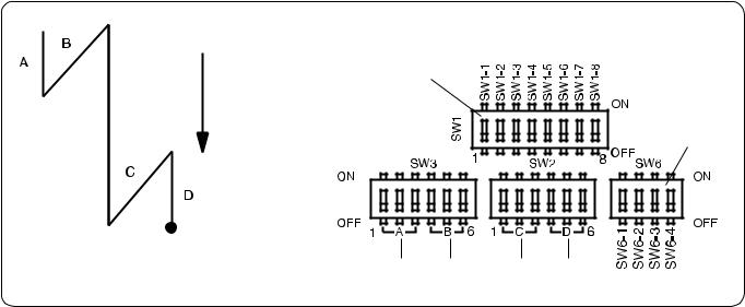
7.5.1.3 Setting the number of backtack stitches
Control circuit board DIP switches
o
!0
t y u i
Display |
|
|
|
A |
|
|
|
|
|
|
B |
|
|
|
|
|
|
C |
|
|
|
|
|
|
D |
|
|
|
|
|
|
|
|
|
|
|
|
|
|
|
|
|
|
|
|
|
|
|
|
|
|
|
|
|
|
|
|
DIPSW No. |
|
|
|
|
|
|
SW3 |
|
|
|
|
|
|
|
|
|
|
|
SW2 |
|
|
|
|
|
||||
|
|
|
|
|
|
|
|
|
|
|
|
|
|
|
|
|
|
|
|
|
|
|
|
|
|
|
|
|
No. of stitches |
1 |
2 |
|
3 |
4 |
5 |
|
6 |
1 |
2 |
|
3 |
4 |
5 |
|
6 |
||||||||||||
|
|
|
|
|
|
|
|
|
|
|
|
|
|
|
|
|
|
|
|
|
|
|
|
|
|
|
|
|
2 |
OFF |
|
OFF |
OFF |
OFF |
|
OFF |
OFF |
OFF |
|
OFF |
OFF |
OFF |
OFF |
OFF |
|||||||||||||
|
|
|
|
|
|
|
|
|
|
|
|
|
|
|
|
|
|
|
|
|
|
|
|
|
|
|
|
|
3 |
ON |
|
OFF |
OFF |
ON |
OFF |
OFF |
ON |
OFF |
OFF |
ON |
OFF |
OFF |
|||||||||||||||
|
|
|
|
|
|
|
|
|
|
|
|
|
|
|
|
|
|
|
|
|
|
|
|
|
|
|
|
|
4 |
OFF |
|
ON |
OFF |
OFF |
|
ON |
OFF |
OFF |
|
ON |
OFF |
OFF |
|
ON |
OFF |
||||||||||||
|
|
|
|
|
|
|
|
|
|
|
|
|
|
|
|
|
|
|
|
|
|
|
|
|
|
|
|
|
5 |
ON |
|
ON |
OFF |
ON |
|
ON |
OFF |
ON |
|
ON |
OFF |
ON |
|
ON |
OFF |
||||||||||||
|
|
|
|
|
|
|
|
|
|
|
|
|
|
|
|
|
|
|
|
|
|
|
|
|
|
|
|
|
6 |
OFF |
|
OFF |
ON |
OFF |
OFF |
ON |
OFF |
OFF |
ON |
OFF |
OFF |
ON |
|||||||||||||||
|
|
|
|
|
|
|
|
|
|
|
|
|
|
|
|
|
|
|
|
|
|
|
|
|
|
|
|
|
7 |
ON |
|
OFF |
ON |
ON |
|
OFF |
ON |
ON |
|
OFF |
ON |
ON |
OFF |
ON |
|||||||||||||
|
|
|
|
|
|
|
|
|
|
|
|
|
|
|
|
|
|
|
|
|
|
|
|
|
|
|
|
|
8 |
OFF |
|
ON |
ON |
OFF |
|
ON |
ON |
OFF |
|
ON |
ON |
OFF |
|
ON |
ON |
||||||||||||
|
|
|
|
|
|
|
|
|
|
|
|
|
|
|
|
|
|
|
|
|
|
|
|
|
|
|
|
|
9 |
ON |
|
ON |
ON |
ON |
|
ON |
ON |
ON |
|
ON |
ON |
ON |
|
ON |
ON |
||||||||||||
|
|
|
|
|
|
|
|
|
|
|
|
|
|
|
|
|
|
|
|
|
|
|
|
|
|
|
|
|
•Setting the number of start backtack stitches
Use switches t of DIP switch 3 to set the number of start backtacking stitches A. Use switches y of DIP switch 3 to set the number of start backtacking stitches B.
•Setting the number of end backtack stitches
Use switches u of DIP switch 2 to set the number of end backtacking stitches C. Use switches i of DIP switch 2 to set the number of end backtacking stitches D.
Note:
At the time of shipment from the factory, DIP switches A, B, C and D are all set to OFF. As a result, the number of stitches is set to 2 for each of A, B, C and D.
When using an operation panel, backtacking functions using the control box are all disabled.
16 |
MD-602, 612 |
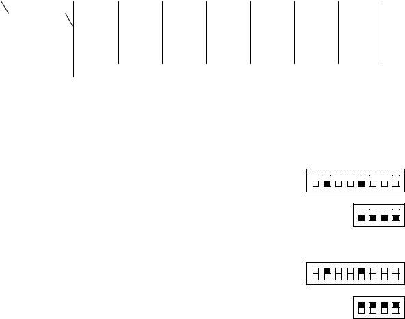
7.5.2 Other DIP switch functions
7.5.2.1DIP switch 1 o functions
SW1-1 |
|
ON |
|
Presser foot is lowered when treadle is returned to neutral position immediately after thread trimming. (Export specifications) |
||||||||||||||||||||||||||||||||||||||||||||||||||||||||||||||||||||||||||||||||||||||||||||||||||||||||||||||||||||||
|
|
|
|
|
|
|
|
|
|
|
|
|
|
|
|
|
|
|
|
|
|
|
|
|
|
|
|
|
|
|
|
|
|
|
|
|
|
|
|
|
|
|
|
|
|
|
|
|
|
|
|
|
|
|
|
|
|
|
|
|
|
|
|
|
|
|
|
|
|
|
|
|
|
|
|
|
|
|
|
|
|
|
|
|
|
|
|
|
|
|
|
|
|
|
|
|
|
|
|
|
|
|
|
|
|
|
|
|
|
|
|
|
|
|
|
|
|
|
|
|
||
OFF |
|
Presser foot is raised when treadle is returned to neutral position immediately after thread trimming. (Domestic Japan specifications) |
||||||||||||||||||||||||||||||||||||||||||||||||||||||||||||||||||||||||||||||||||||||||||||||||||||||||||||||||||||||||
|
|
|
||||||||||||||||||||||||||||||||||||||||||||||||||||||||||||||||||||||||||||||||||||||||||||||||||||||||||||||||||||||||
|
|
|
|
|
|
|
|
|
|
|
|
|
|
|
|
|
|
|
|
|
|
|
|
|
|
|
|
|
|
|
|
|
|
|
|
|
|
|
|
|
|
|
|
|
|
|
|
|
|
|
|
|
|
|
|
|
|
|
|
|
|
|
|
|
|
|
|
|
|
|
|
|
|
|
|
|
|
|
|
|
||||||||||||||||||||||||||||||||||||||||||
SW1-2 |
|
ON |
|
Motor pulley diameter 90 mm |
|
|
|
|
|
|
|
|
|
|
|
|
|
|
|
|
|
|
|
|
|
|
|
|
|
|
|
|
|
|
|
|
|
|
|
|
|
|
|
|
|
|
|
|
|
|
|
|
|
|
|
|
|
|
|
|
|
|
|
|
|
|
|
|
|
|
|
|
|
|
|
|
|
|
|
|||||||||||||||||||||||||||||||||||||||||||
|
|
|
|
|
|
|
|
|
|
|
|
|
|
|
|
|
|
|
|
|
|
|
|
|
|
|
|
|
|
|
|
|
|
|
|
|
|
|
|
|
|
|
|
|
|
|
|
|
|
|
|
|
|
|
|
|
|
|
|
|
|
|
|
|
|
|
|
|
|
|
|
|
|
|
|
|
|
|
|
|
|
|
|
|
|
|
|
|
|
|
|
|
|
|
|
|
|
|
|
|
|
|
|
|
|
|
|
|
|
|
|
|
|
|
|
|
|
|
|
|
||
OFF |
|
Motor pulley diameter 105 mm |
|
|
|
|
|
|
|
|
|
|
|
|
|
|
|
|
|
|
|
|
|
|
|
|
|
|
|
|
|
|
|
|
|
|
|
|
|
|
|
|
|
|
|
|
|
|
|
|
|
|
|
|
|
|
|
|
|
|
|
|
|
|
|
|
|
|
|
|
|
|
|
|
|
|
|
|||||||||||||||||||||||||||||||||||||||||||||
|
|
|
|
|
|
|
|
|
|
|
|
|
|
|
|
|
|
|
|
|
|
|
|
|
|
|
|
|
|
|
|
|
|
|
|
|
|
|
|
|
|
|
|
|
|
|
|
|
|
|
|
|
|
|
|
|
|
|
|
|
|
|
|
|
|
|
|
|
|
|
|
|
|
|
|
|
|
|||||||||||||||||||||||||||||||||||||||||||||
|
|
|
|
|
|
|
|
|
|
|
|
|
|
|
|
|
|
|
|
|
|
|
|
|
|
|
|
|
|
|
|
|
|
|
|
|
|
|
|
|
|
|
|
|
|
|
|
|
|
|
|
|
|
|
|
|
|
|
|
|
|
|
|
|
|
|
|
|
||||||||||||||||||||||||||||||||||||||||||||||||||||||
SW1-3 |
|
ON |
|
Automatic presser foot lifter device used |
|
|
|
|
|
|
|
|
|
|
|
|
|
|
|
|
|
|
|
|
|
|
|
|
|
|
|
|
|
|
|
|
|
|
|
|
|
|
|
|
|
|
|
|
|
|
|
|
|
|
|
|
|
|
|
|
|
|
|
|
|
|
|
|||||||||||||||||||||||||||||||||||||||||||||||||||||||
|
|
|
|
|
|
|
|
|
|
|
|
|
|
|
|
|
|
|
|
|
|
|
|
|
|
|
|
|
|
|
|
|
|
|
|
|
|
|
|
|
|
|
|
|
|
|
|
|
|
|
|
|
|
|
|
|
|
|
|
|
|
|
|
|
|
|
|
|
|
|
|
|
|
|
|
|
|
|
|
|
|
|
|
|
|
|
|
|
|
|
|
|
|
|
|
|
|
|
|
|
|
|
|
|
|
|
|
|
|
|
|
|
|
|
|
|
|
|
|
|
||
OFF |
|
Automatic presser foot lifter device not used |
|
|
|
|
|
|
|
|
|
|
|
|
|
|
|
|
|
|
|
|
|
|
|
|
|
|
|
|
|
|
|
|
|
|
|
|
|
|
|
|
|
|
|
|
|
|
|
|
|
|
|
|
|
|
|
|
|
|
|
|
|
|
|
|||||||||||||||||||||||||||||||||||||||||||||||||||||||||
|
|
|
|
|
|
|
|
|
|
|
|
|
|
|
|
|
|
|
|
|
|
|
|
|
|
|
|
|
|
|
|
|
|
|
|
|
|
|
|
|
|
|
|
|
|
|
|
|
|
|
|
|
|
|
|
|
|
|
|
|
|
|
|
|
|
|||||||||||||||||||||||||||||||||||||||||||||||||||||||||
|
|
|
|
|
|
|
|
|
|
|
|
|
|
|
|
|
|
|
|
|
|
|
|
|
|
|
|
|
|
|
|
|
|
|
|
|
|
|
|
|
|
|||||||||||||||||||||||||||||||||||||||||||||||||||||||||||||||||||||||||||||||||
SW1-4 |
|
ON |
|
Stopping position when treadle is at neutral is needle up stop position. |
|
|
|
|
|
|
|
|
|
|
|
|
|
|
|
|
|
|
|
|
|
|
|
|
|
|
|
|
|
|
|
|
|
|
|
|
||||||||||||||||||||||||||||||||||||||||||||||||||||||||||||||||||||||||||||||||||
|
|
|
|
|
|
|
|
|
|
|
|
|
|
|
|
|
|
|
|
|
|
|
|
|
|
|
|
|
|
|
|
|
|
|
|
|
|
|
|
|
|
|
|
|
|
|
|
|
|
|
|
|
|
|
|
|
|
|
|
|
|
|
|
|
|
|
|
|
|
|
|
|
|
|
|
|
|
|
|
|
|
|
|
|
|
|
|
|
|
|
|
|
|
|
|
|
|
|
|
|
|
|
|
|
|
|
|
|
|
|
|
|
|
|
|
|
|
|
|
|
||
OFF |
|
Stopping position when treadle is at neutral is needle down stop position. |
|
|
|
|
|
|
|
|
|
|
|
|
|
|
|
|
|
|
|
|
|
|
|
|
|
|
|
|||||||||||||||||||||||||||||||||||||||||||||||||||||||||||||||||||||||||||||||||||||||||||||
|
|
|
|
|
|
|
|
|
|
|
|
|
|
|
|
|
|
|
|
|
|
|
|
|
|
|
|
|
|
|||||||||||||||||||||||||||||||||||||||||||||||||||||||||||||||||||||||||||||||||||||||||||||
|
|
|
|
|
|
|
|
|
|
|
|
|
|
|
|
|
|
|
|
|
|
|
|
|
|
|
|
|
|
|
|
|
|
|
|
|
|
|
|
|
|
|
|
|
|
|
|
|
|
|
|
|
|
|
|
|
|
|
|
|
|
|
|
|
|
|
|
|
|
|
|
|
|
|
|
|
|
|
|
|
|
|
|
|
|
|
|
|
|
|
|
|
|
|
|
|
|
|
|
|
|
|
|
|||||||||||||||||||
SW1-5 |
|
ON |
|
Twin needle |
|
|
|
|
|
|
|
|
|
|
|
|
|
|
|
|
|
|
|
|
|
|
|
|
|
|
|
|
|
|
|
|
|
|
|
|
|
|
|
|
|
|
|
|
|
|
|
|
|
|
|
|
|
|
|
|
|
|
|
|
|
|
|
|
|
|
|
|
|
|
|
|
|
|
|
|
|
|
|
|
|
|
|
|
|
|
|
|
|
|
|
|
|
|
|
|
|
|
||||||||||||||||||||
|
|
|
|
|
|
|
|
|
|
|
|
|
|
|
|
|
|
|
|
|
|
|
|
|
|
|
|
|
|
|
|
|
|
|
|
|
|
|
|
|
|
|
|
|
|
|
|
|
|
|
|
|
|
|
|
|
|
|
|
|
|
|
|
|
|
|
|
|
|
|
|
|
|
|
|
|
|
|
|
|
|
|
|
|
|
|
|
|
|
|
|
|
|
|
|
|
|
|
|
|
|
|
|
|
|
|
|
|
|
|
|
|
|
|
|
|
|
|
|
|
||
OFF |
|
Single needle |
|
|
|
|
|
|
|
|
|
|
|
|
|
|
|
|
|
|
|
|
|
|
|
|
|
|
|
|
|
|
|
|
|
|
|
|
|
|
|
|
|
|
|
|
|
|
|
|
|
|
|
|
|
|
|
|
|
|
|
|
|
|
|
|
|
|
|
|
|
|
|
|
|
|
|
|
|
|
|
|
|
|
|
|
|
|
|
|
|
|
|
|
|
|
|
|
|
|
||||||||||||||||||||||
|
|
|
|
|
|
|
|
|
|
|
|
|
|
|
|
|
|
|
|
|
|
|
|
|
|
|
|
|
|
|
|
|
|
|
|
|
|
|
|
|
|
|
|
|
|
|
|
|
|
|
|
|
|
|
|
|
|
|
|
|
|
|
|
|
|
|
|
|
|
|
|
|
|
|
|
|
|
|
|
|
|
|
|
|
|
|
|
|
|
|
|
|
|
|
|
|
|
|
|
|
||||||||||||||||||||||
|
|
|
|
|
|
|
|
|
|
|
|
|
|
|
|
|
|
|
|
|
|
|
|
|
|
|
|
|
|
|
|
|
|
|
|
|
|
|
|
|
|
|
|
|
|
|
|
|
|
|
|
|
|
|
|
|
|
|
|
|
|
|
|
|
|
|
|
|
|
|
|
|
|
|
|
|
|
|
|
|
|
|
|
|
|
|
|
|
|
|
|
|
||||||||||||||||||||||||||||||
SW1-6 |
|
ON |
|
Limit speed setting 1 |
|
|
|
|
|
|
|
|
|
|
|
|
|
|
|
|
|
|
|
|
|
|
|
|
|
|
|
|
|
|
|
|
|
|
|
|
|
|
|
|
|
|
|
|
|
|
|
|
|
|
|
|
|
|
|
|
|
|
|
|
|
|
|
|
|
|
|
|
|
|
|
|
|
|
|
|
|
|
|
|
|
|
|
|
|
|
|
|||||||||||||||||||||||||||||||
|
|
|
|
|
|
|
|
|
|
|
|
|
|
|
|
|
|
|
|
|
|
|
|
|
|
|
|
|
|
|
|
|
|
|
|
|
|
|
|
|
|
|
|
|
|
|
|
|
|
|
|
|
|
|
|
|
|
|
|
|
|
|
|
|
|
|
|
|
|
|
|
|
|
|
|
|
|
|
|
|
|
|
|
|
|
|
|
|
|
|
|
|
|
|
|
|
|
|
|
|
|
|
|
|
|
|
|
|
|
|
|
|
|
|
|
|
|
|
|
|
||
OFF |
|
|
|
|
|
|
|
|
|
|
|
|
|
|
|
|
|
|
|
|
|
|
|
|
|
|
|
|
|
|
|
|
|
|
|
|
|
|
|
|
|
|
|
|
|
|
|
|
|
|
|
|
|
|
|
|
|
|
|
|
|
|
|
|
|
|
|
|
|
|
|
|
|
|
|
|
|
|
|
|
|
|
|
|
|
|
|
|
|
|
|
|
|
|
|
|
|
|
|
|
|
|
|
|
|
|
|
|
|
|
|
|
|
|
||||||||
|
|
|
|
|
|
|
|
|
|
|
|
|
|
|
|
|
|
|
|
|
|
|
|
|
|
|
|
|
|
|
|
|
|
|
|
|
|
|
|
|
|
|
|
|
|
|
|
|
|
|
|
|
|
|
|
|
|
|
|
|
|
|
|
|
|
|
|
|
|
|
|
|
|
|
|
|
|
|
|
|
|
|
|
|
|
|
|
|
|
|
|
|
|
|
|
|
|
|
|
|
|
|
|
|
|
|
|
|
|
|
|
|
|
|
|
|||||||
|
|
|
|
|
|
|
|
|
|
|
|
|
|
|
|
|
|
|
|
|
|
|
|
|
|
|
|
|
|
|
|
|
|
|
|
|
|
|
|
|
|
|
|
|
|
|
|
|
|
|
|
|
|
|
|
|
|
|
|
|
|
|
|
|
|
|
|
|
|
|
|
|
|
|
|
|
|
|
|
|
|
|
|
|
|
|
|
|
|
|
|
|
||||||||||||||||||||||||||||||
SW1-7 |
|
ON |
|
Limit speed setting 2 |
|
|
|
|
|
|
|
|
|
|
|
|
|
|
|
|
|
|
|
|
|
|
|
|
|
|
|
|
|
|
|
|
|
|
|
|
|
|
|
|
|
|
|
|
|
|
|
|
|
|
|
|
|
|
|
|
|
|
|
|
|
|
|
|
|
|
|
|
|
|
|
|
|
|
|
|
|
|
|
|
|
|
|
|
|
|
|
|||||||||||||||||||||||||||||||
|
|
|
|
|
|
|
|
|
|
|
|
|
|
|
|
|
|
|
|
|
|
|
|
|
|
|
|
|
|
|
|
|
|
|
|
|
|
|
|
|
|
|
|
|
|
|
|
|
|
|
|
|
|
|
|
|
|
|
|
|
|
|
|
|
|
|
|
|
|
|
|
|
|
|
|
|
|
|
|
|
|
|
|
|
|
|
|
|
|
|
|
|
|
|
|
|
|
|
|
|
|
|
|
|
|
|
|
|
|
|
|
|
|
|
|
|
|
|
|
|
||
OFF |
|
|
|
|
|
|
|
|
|
|
|
|
|
|
|
|
|
|
|
|
|
|
|
|
|
|
|
|
|
|
|
|
|
|
|
|
|
|
|
|
|
|
|
|
|
|
|
|
|
|
|
|
|
|
|
|
|
|
|
|
|
|
|
|
|
|
|
|
|
|
|
|
|
|
|
|
|
|
|
|
|
|
|
|
|
|
|
|
|
|
|
|
|
|
|
|
|
|
|
|
|
|
|
|
|
|
|
|
|
|
|
|
|
|
||||||||
|
|
|
|
|
|
|
|
|
|
|
|
|
|
|
|
|
|
|
|
|
|
|
|
|
|
|
|
|
|
|
|
|
|
|
|
|
|
|
|
|
|
|
|
|
|
|
|
|
|
|
|
|
|
|
|
|
|
|
|
|
|
|
|
|
|
|
|
|
|
|
|
|
|
|
|
|
|
|
|
|
|
|
|
|
|
|
|
|
|
|
|
|
|
|
|
|
|
|
|
|
|
|
|
|
|
|
|
|
|
|
|
|
|
|
|
|||||||
|
|
|
|
|
|
|
|
|
|
|
|
|
|
|
|
|
|
|
|
|
|
|
|
|
|
|
|
|
|
|
|
|
|
|
|
|
|
|
|
|
|
|
|
|
|
|
|
|
|
|
|
|
|
|
|
|
|
|
|
|
|
|
|
|
|
|
|
|
|
|
|
|
|
|
|
|
|
|
|
|
|
|
|
|
|
|
|
|
|
|
|
|
||||||||||||||||||||||||||||||
SW1-8 |
|
ON |
|
Limit speed setting 3 |
|
|
|
|
|
|
|
|
|
|
|
|
|
|
|
|
|
|
|
|
|
|
|
|
|
|
|
|
|
|
|
|
|
|
|
|
|
|
|
|
|
|
|
|
|
|
|
|
|
|
|
|
|
|
|
|
|
|
|
|
|
|
|
|
|
|
|
|
|
|
|
|
|
|
|
|
|
|
|
|
|
|
|
|
|
|
|
|||||||||||||||||||||||||||||||
|
|
|
|
|
|
|
|
|
|
|
|
|
|
|
|
|
|
|
|
|
|
|
|
|
|
|
|
|
|
|
|
|
|
|
|
|
|
|
|
|
|
|
|
|
|
|
|
|
|
|
|
|
|
|
|
|
|
|
|
|
|
|
|
|
|
|
|
|
|
|
|
|
|
|
|
|
|
|
|
|
|
|
|
|
|
|
|
|
|
|
|
|
|
|
|
|
|
|
|
|
|
|
|
|
|
|
|
|
|
|
|
|
|
|
|
|
|
|
|
|
||
OFF |
|
|
|
|
|
|
|
|
|
|
|
|
|
|
|
|
|
|
|
|
|
|
|
|
|
|
|
|
|
|
|
|
|
|
|
|
|
|
|
|
|
|
|
|
|
|
|
|
|
|
|
|
|
|
|
|
|
|
|
|
|
|
|
|
|
|
|
|
|
|
|
|
|
|
|
|
|
|
|
|
|
|
|
|
|
|
|
|
|
|
|
|
|
|
|
|
|
|
|
|
|
|
|
|
|
|
|
|
|
|
|
|
|
|
||||||||
|
|
|
|
|
|
|
|
|
|
|
|
|
|
|
|
|
|
|
|
|
|
|
|
|
|
|
|
|
|
|
|
|
|
|
|
|
|
|
|
|
|
|
|
|
|
|
|
|
|
|
|
|
|
|
|
|
|
|
|
|
|
|
|
|
|
|
|
|
|
|
|
|
|
|
|
|
|
|
|
|
|
|
|
|
|
|
|
|
|
|
|
|
|
|
|
|
|
|
|
|
|
|
|
|
|
|
|
|
|
|
|
|
|
|
|
|||||||
|
|
|
|
|
|
|||||||||||||||||||||||||||||||||||||||||||||||||||||||||||||||||||||||||||||||||||||||||||||||||||||||||||||||||||||
Setting for limit speed (sewing machine’s maximum sewing speed) ( |
|
) is for overlock machines |
||||||||||||||||||||||||||||||||||||||||||||||||||||||||||||||||||||||||||||||||||||||||||||||||||||||||||||||||||||||||
|
|
|
|
|
|
|
|
|
|
|
|
|
|
|
|
|
|
|
|
|
|
|
|
|
|
|
|
|
|
|
||||||||||||||||||||||||||||||||||||||||||||||||||||||||||||||||||||||||||||||||||||||||||||
|
Speed (rpm) |
1,000 |
|
2,000 |
2,500 |
3,000 |
3,500 |
|
4,000 |
|
|
|
|
4,500 |
4,700 |
|
|
|
|
|
|
|
|
|
|
|
|
|
|
|
||||||||||||||||||||||||||||||||||||||||||||||||||||||||||||||||||||||||||||||||||||||||||||
|
DIP switch |
|
|
|
(5,000) |
|
(5,500) |
(6,000) |
(6,500) |
(7,000) |
(7,500) |
|
|
|
(8,000) |
(8,500) |
|
|
|
|
|
|
|
|
|
|
|
|
|
|
||||||||||||||||||||||||||||||||||||||||||||||||||||||||||||||||||||||||||||||||||||||||||||
|
|
|
|
|
|
|
|
|
|
|
|
|
|
|
|
|
|
|
|
|
|
|
|
|
|
|
|
|
|
|
|
|
|
|
|
|
|
|
|
|
|
|
|
|
|
|
|
|
|
|
|
|
|
|
|
|
|
|
|
|
|
|
|
|
|
|
|
|
|
|
|
|
|
|
|
|
|
|
|
|
|
|
|
|
|
|
|
|
|
|
|
|
|
|
|
|
|
|
|
|
|
|
|
|
|
|
|
|
|
|
|
|
|
|
|
|
|
|
|
|
|
|
|
SW1-6 |
|
|
|
|
|
|
|
|
OFF |
|
|
|
|
|
ON |
|
|
|
|
|
|
OFF |
|
|
|
|
|
|
ON |
|
|
|
|
|
|
OFF |
|
|
|
|
|
|
ON |
|
|
|
OFF |
|
|
|
|
|
|
ON |
|
||||||||||||||||||||||||||||||||||||||||||||||||||||||||||||||||||
|
|
|
|
|
|
|
|
|
|
|
|
|
|
|
|
|
|
|
|
|
|
|
|
|
|
|
|
|
|
|
|
|
|
|
|
|
|
|
|
|
|
|
|
|
|
|
|
|
|
|
|
|
|
|
|
|
|
|
|
|
|
|
|
|
|
|
|
|
|
|
|
|
|
|
|
|
|
|
|
|
|
|
|
|
|
|
|
|
|
|
|
|
|
|
|
|
|
|
|
|
|
|
|
|
|
|
|
|
|
|
|
|
|
|
|
|
|
|
|
|
|
|
|
SW1-7 |
|
|
|
|
|
|
|
|
OFF |
|
|
|
|
|
OFF |
|
|
|
|
|
|
ON |
|
|
|
|
|
|
ON |
|
|
|
|
|
|
OFF |
|
|
|
|
|
|
OFF |
|
|
|
ON |
|
|
|
|
|
|
ON |
|
||||||||||||||||||||||||||||||||||||||||||||||||||||||||||||||||||
|
|
|
|
|
|
|
|
|
|
|
|
|
|
|
|
|
|
|
|
|
|
|
|
|
|
|
|
|
|
|
|
|
|
|
|
|
|
|
|
|
|
|
|
|
|
|
|
|
|
|
|
|
|
|
|
|
|
|
|
|
|
|
|
|
|
|
|
|
|
|
|
|
|
|
|
|
|
|
|
|
|
|
|
|
|
|
|
|
|
|
|
|
|
|
|
|
|
|
|
|
|
|
|
|
|
|
|
|
|
|
|
|
|
|
|
|
|
|
|
|
|
|
|
SW1-8 |
|
|
|
|
|
|
|
|
OFF |
|
|
|
|
|
OFF |
|
|
|
|
|
|
OFF |
|
|
|
|
|
|
OFF |
|
|
|
|
|
|
ON |
|
|
|
|
|
|
ON |
|
|
|
ON |
|
|
|
|
|
|
ON |
|
||||||||||||||||||||||||||||||||||||||||||||||||||||||||||||||||||
|
|
|
|
|
|
|
|
|
|
|
|
|
|
|
|
|
|
|
|
|
|
|
|
|
|
|
|
|
|
|
|
|
|
|
|
|
|
|
|
|
|
|
|
|
|
|
|
|
|
|
|
|
|
|
|
|
|
|
|
|
|
|
|
|
|
|
|
|
|
|
|
|
|
|
|
|
|
|
|
|
|
|
|
|
|
|
|
|
|
|
|
|
|
|
|
|
|
|
|
|
|
|
|
|
|
|
|
|
|
|
|
|
|
|
||||||||
Pulley diameter |
|
|
105 mm for single-needle machines and overlock machines (90 mm for twin-needle machines) |
|
||||||||||||||||||||||||||||||||||||||||||||||||||||||||||||||||||||||||||||||||||||||||||||||||||||||||||||||||||||||
|
|
|
|
|
|
|
|
|
|
|
|
|
|
|
|
|
|
|
|
|
|
|
|
|
|
|
|
|
|
|
|
|
|
|
|
|
|
|
|
|
|
|
|
|
|
|
|
|
|
|
|
|
|
|
|
|
|
|
|
|
|
|
|
|
|
|
|
|
|
|
|
|
|
|
|
|
|
|
|
|
|
|
|
|
|
|
|
|
|
|
|
|
|
|
|
|
|
|
|
|
|
|
|
|
|
|
|
|
|
|
|
|
|
|
|
|
|
|
|
|
|
|
Note:
When an operation panel has been connected, the operation panel setting has priority, regardless of the setting for DIP switch 1-4.
Only the maximum sewing speed can be changed using the DIP switch 1-5 setting.
Refer to “7.5.2.2 DIP switch 6 !0functions” on this page for other speed selection settings.
7.5.2.2 DIP switch 6 !0functions
DIP switch |
|
|
Setting speed |
|
|
|
|
|
|
SW6-1 |
Low speed |
ON |
250 rpm |
|
(inching speed) |
OFF |
215 rpm |
||
|
||||
|
|
|
|
|
SW6-2 |
Thread trimming |
ON |
185 rpm |
|
speed |
OFF |
215 rpm |
||
|
||||
|
|
|
|
|
SW6-3 |
Backtacking speed |
ON |
1,000 rpm |
|
|
|
|||
OFF |
1,800 rpm |
|||
|
|
|||
|
|
|
|
|
SW6-4 |
Improved stopping |
ON |
1,500 rpm |
|
speed |
OFF |
1,700 rpm |
||
|
||||
|
|
|
|
Note:
DIP switches 1 – 2, 1 – 5 and 6 (1 – 4) are set to match the optimum sewing speed for the machine head, and so should not be changed. If using the motor after changing over the machine head, check that the above settings match the specifications of the machine head.
7.6 Periodic checks
Single-needle machine and overlock machines setting
High
SW1
-1 -2 -3 -4
SW6

Twin-needle machine setting
High
SW1
-1 -2 -3 -4
SW6

•Clean the dust out of the dust cover at periodic intervals. If the dust cover becomes blocked, there is the danger that the motor may overheat.
•If not using the motor for long periods, turn off the power and disconnect the motor from the power supply.
MD-602, 612 |
17 |
Loading...