


MD-6020 |
-fi,EijljtP.,ij~ |
|
|
INSTRUCTION MANUAL |
|
Single-phase power specifications |
MANUAL DE INSTRUCCIONES |
|
$4SEI!illl. |
||
|
||
Especiflcaciones de alimentaci6n de fase unica |
|
|
MD-6120 |
|
|
Three-phase power specifications |
|
|
:4SEI!iill~ |
|
|
Especificacion~s de alimentaci6n de tres fases |
|
|
|
|
|
|
|
AC SERVOMOTOR
Please read this instruction manual before using the machine.
Please keep this instruction manual within easy reach for quick reference.
SERVOMOTOR DE AC
Por favor lea este manual de instrucciones antes de usar Ia maquina.
Por favor guarde este manual de instrucciones al alcance de Ia mano para una rapida referencia.
From the library of: Superior Sewing Machine & Supply LLC

AC SERVOMOTOR
MD-6020 MD-6120
Single-phase power specifications
Three-phase power specifications
CONTENTS
SAFETY INSTRUCTIONS ................................ |
|
||
1. SAFETY INDICATIONS AND THEIR |
|
||
|
MEANINGS ................................................... |
|
|
2. CAUTIONS WITH REGARD TO |
|
||
|
SAFETY.......................................................... |
|
ii |
3. |
WARNING I..ABEL ........................................ |
ii |
|
1. SPECIFICATIONS ......................................... |
|
||
2. |
UNDERSTANDING THE RATING PLATE ...... |
1 |
|
3. |
INSTALI..ATION ............................................. |
2 |
|
|
3-1. Installing the motor to the work |
|
|
|
table......................................................... |
|
2 |
|
3-2. Attaching the belt................................... |
2 |
|
|
3-3. Installing the belt cover......................... |
3 |
|
|
3-4. Connecting the connecting rod ............ |
3 |
|
|
3-5. Adjusting the belt cover safety |
|
|
|
mechanisms ............................................ |
3 |
|
|
3-5-1. |
Adjusting the belt casting |
|
|
|
prevention guide......................... |
3 |
|
3-5-2. |
Adjusting the finger guard......... |
3 |
|
3-6. Connecting the cords............................. |
4 |
|
|
3-6-1. |
Connecting the power cord, |
|
|
|
power switch and ground |
|
|
|
cord............................................... |
4 |
|
3-6-2. |
Connecting the sewing machine |
|
|
|
and control box ........................... |
4,5 |
|
3-7. Installing the head lamp........................ |
6 |
|
|
3·8. Connecting the external operation |
|
|
|
panel........................................................ |
|
6 |
4. ADJUSTING THE TREADLE UNIT .......... |
7 |
||
|
4-1. Operating the treadle............................. |
7 |
|
|
4-1-1. For treadles with one forward |
|
|
|
|
and one rear stage...................... |
7 |
|
4-1-2. For treadles with two forward |
|
|
|
|
and two rear stages.................... |
7 |
4-2. |
Adjusting the treadle ............................. |
|
8 |
|
|
4-2-1. |
Adjusting the treadle pressure |
.. 8 |
|
|
4-2-2. |
Adjusting the treadle return |
|
|
|
|
pressure....................................... |
|
8 |
|
4-2-3. |
Adjusting the treadle stroke ...... |
8 |
|
4-3. When using the automatic presser foot |
||||
|
lifter device ............................................. |
|
8 |
|
5. USING THE CONTROL BOX .................... |
9 |
|||
5-1. Power switch and power indicator....... |
9 |
|||
5-2. |
Setting the sewing speed ...................... |
9 |
||
5-3. Control box DIP switch setting |
|
|||
|
procedure................................................ |
|
9 |
|
5-4. |
Description of functions ........................ |
10 |
||
|
5-4-1. |
Backtacking function using |
|
|
|
|
the control box when no |
|
|
|
|
operation panel is installed ....... |
10 |
|
|
5-4-2. |
Other DIP switch functions ........ |
11 |
|
5-5. |
Periodic checks ....................................... |
|
11 |
|
6. CONNECTING OPTIONS |
........................... |
12 |
||
6-1. Connecting the pedal for standing |
12 |
|||
|
operations ............................... |
................ |
||
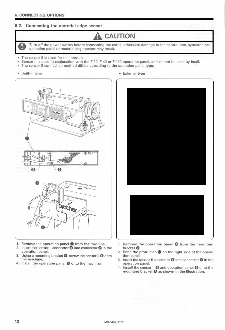
6-2. Connecting the material edge sensor .. 13 |
||||
7. TROUBLESHOOTING ................................. |
|
14 |
||
7-1. |
Error display and their meanings ......... |
14 |
||
8. USING THE OPERATION PANEL F-40 ... |
15 |
|||
8-1. Changing the machine head |
|
|||
|
settings ......................... |
·........................... |
15 |
|
|
8-1-1. Setting procedure ....................... |
15 |
||
|
8-1-2. |
Initializing the machine head |
|
|
|
|
setting value ................................ |
|
15 |
|
8-1-3. |
Machine head setting mode |
|
|
|
|
list ............................................. |
|
15,16 |
|
8-1-4. |
Other machine sewing |
|
|
|
|
speeds .......................................... |
|
16 |
8-2. Setting the sewing speed to match |
17 |
|||
|
the machine head ................................... |
|
||
From the library of: SuperiorMD-6020,Sewing6120 Machine & Supply LLC

Thank you for purchasing this Brother general-purpose sewing machine motor. Before using the motor, please be sure to read the Safety Instructions and the explanations of how to use the motor which are contained in this manual.
Furthermore, because we are continually improving our products as a result of continuing research, the specifications for the product which you have purchased may differ slightly from those listed in this manual.
SAFETY INSTRUCTIONS
1. SAFETY INDICATIONS AND THEIR MEANINGS
This instruction manual and the indications and symbols that are used on the machine itself are provided in order to ensure safe operation of this machine and to prevent accidents and injury to yourself or other people.
The meanings of these indications and symbols are given below.
Indications
A WARNING |
Failure to observe the instruction which appears after this indication while using the motor |
will result in death or severe injury to the user. |
|
|
|
A CAUTION |
Failure to observe the instructions which appear after this indication while using the motor |
may result in slight to moderate injury to the user, or physical damage. |
|
|
|
Symbols
The symbols which are used in this manual and their meanings are shown below.
~This symbol is used to indicate the danger of ~lectric shocks.
Lh |
This symbol is used to indicate general cautions that should be observed. |
•This symbol is used to indicate that the ground connection must be made.
0 |
This symbol is used to indicate general actions which you must do. |
|
2. CAUTIONS WITH REGARD TO SAFETY
Following is a compilation of all the warnings and cautions which appear throughout this manual.
A WARNING
A Wait at least 5 minutes after turning off the power switch before opening the cover of the control box. Touching areas ~ where high voltages are present can result in severe injury.
A CAUTION
~
Lll
0
Do not use the motor near sources of strong electrical interference. If the motor is installed in a location which is close to sources of strong electrical interference such as high-frequency welders, it may cause problems with correct operation of the sewing machine.
Disconnect the power cord plug from the wall outlet before installing the motor.
The motor and control box weigh approximately 12 kg. Take care not to drop them on your feet when installing or removing them from the work table.
Be sure to tighten the nuts securely.
If they are not tightened properly, it could cause the sewing machine to vibrate or shift its position while sewing.
From the library of: SuperiorMDSewing-6020, 6120 Machine & Supply LLC

A CAUTION
0
0
•
Turn off the power switch and wait for the power indicator on the panel display to turn off before connecting and disconnecting any of the connectors.
Turn off the power switch before inserting or removing the AC power cord plug.
Be sure to connect the power supply to a secure ground. If the ground is not securely connected, electric shocks may result.
0 |
Use a lamp which is rated at 6 V AC and 20 W or less as the head lamp. |
|
|
|
If a lamp with a higher rating than this is used, it could cause the lamp wires and the transformer to overheat and burn |
|
out. |
0
~
0
0
0
0
0
Confirm that the power supply matches the motor and the control box specifications before turning on the power switch. The motor, control box or sewing machine could be damaged if the supply voltage is too high.
Do not clamp the cords inside the control box when closing the control box cover.
Turn off the power switch before connecting the cords, otherwise damage to the control box, synchronizer, operation panel or material edge sensor may result.
Any fluctuations in the power supply voltage should be within ±1 0% of the rated voltage for the motor.
Voltage fluctuations which are greater than this may cause problems with correct operation of the sewing machine.
Use a power supply with a capacity which is in excess of the motor power capacity.
Insufficient power supply capacity may cause problems with correct operation of the sewing machine.
The ambient temperature should be within the range of soc to 35°C during use.
Temperatures which are lower or higher than this may cause problems with correct operation of the sewing machine.
The relative humidity should be within the range of 45% to 85% during use, and no dew formation should occur in any devices.
Excessively dry or humid environments and dew formation may cause problems with correct operation of the sewing machine.
0
0
Avoid exposure to direct sunlight during use.
Exposure to direct sunlight may cause problems with correct operation of the sewing machine.
In the event of an electrical storm, turn off the power and disconnect the power cord from the wall outlet. Lightning may cause problems with correct operation of the sewing machine.
3. WARNING LABEL
The warning label shown below is affixed to the cover of the control box. Please follow the instructions on the label at all times when using the motor. If the label has been removed or is difficult to read, please contact your nearest Brother dealer.
|
|
|
|
|
|
|
|
|
|
|
|
|
|
|
|
|
|
|
A DANGER AGEFAHR |
A DANGER |
A PELIGRO |
|
|
|
|
|
Hazardous voltage |
Hochspannung |
Un voltage non adapte |
Un voltaje inadecuado |
|
|
|
|
will cause injury. |
verletzungsgefaM |
provoque des blessures. |
puede provocar las |
|
|
|
|
Tum off main |
Bitte schalten sie den |
Eteindrel'interrupteuret |
heridas. |
|
|
|
|
Apagar el interrupter |
|
|||
|
|
|
switch and wait 5 |
hauptschalter ailS und |
attendre 5minutes |
|
|
|
|
|
minutes before |
warten sie 5minuten, |
avantd'ouvrir le capot |
principal yesperar 5 |
|
|
|
|
opening this cover. |
bevor sie diese |
|
minutos antes de abrir |
|
|
|
|
|
abdeckung offnen. |
|
esta cubierta. |
|
|
|
|
|
|
|
|
|
|
|
|
|
|
|
|
|
|
|
|
|
|
|
|
|
Warning label --- . /
From the library of: Superior Sewing Machine & Supply LLC |
ii |
MD-6020, 6120 |

1.SPECIFICATIONS
2.UNDERSTANDING THE RATING PLATE
1.SPECIFICATIONS
p~ |
|
Single-phase 110 V, |
Single-phase 220 V/230 V/240 V/ |
|
3-phase 220 V, |
|||||||
|
|
50/60Hz |
|
I |
CE-compliant 230 V, 50/60Hz |
|
50/60Hz |
|||||
|
|
|
|
|
MD-6020 |
|
MD-6120 |
|||||
|
|
Model |
|
|
|
|
|
M-60C |
|
|||
|
|
Type |
|
|
|
|
Induction motor |
|
||||
Motor |
Rated output |
|
|
|
|
|
400W |
|
||||
|
|
Rated speed |
|
|
|
|
1 |
|
|
|
||
|
|
|
|
|
|
3,500 min· |
|
|||||
|
|
Insulation class |
|
|
|
|
|
Type E |
|
|||
|
|
Voltage |
|
110 v |
|
I |
220 V/230 V/240 VICE-compliant 230 V |
|
|
220 v |
||
|
|
Speed control range |
|
|
Up to 5,000 rpm (Overlocking: Max. 8,500 rpm) |
|
||||||
|
|
(machine shaft) |
|
|
|
|||||||
|
|
|
|
|
|
|
|
|
|
|
||
|
|
|
|
|
|
|
|
|
|
|||
|
|
Solenoid resistance |
|
|
|
|
10 Q or more |
|
||||
Control |
Allowable voltage fluctuation |
|
|
|
|
±10% |
|
|
|
|||
box |
|
Operating temperature |
|
|
|
|
5°C- 35°C |
|
||||
|
|
Operating humidity |
|
|
|
45% - 80% R.H. (no condensation) |
|
|||||
|
|
Storage temperature/humidity |
|
|
|
|
-20°C - 60°C, 25% - 90% R.H. |
|
||||
|
|
Weight |
|
|
|
|
12 kg (Main unit) |
|
||||
|
|
|
|
|
|
|
|
|
|
|
|
|
|
|
Dimensions |
|
|
343 (W) x 324 (H) x 195 (D) mm (Main unit) |
|
||||||
|
|
|
|
|
|
|
|
|
|
|
|
|
2. UNDERSTANDING THE RATING PLATE
Example: Control box (Single-phase 220 V specifications)
brother |
OUT PUT |
400 W |
||
|
SINGLE PHASE |
|||
MD-6020 |
|
VOLTS |
rnQJ 230 240 |
|
184-4239-BO |
|
HERTZ |
|
50/60 |
CONTROL BOX |
|
FOR |
|
M-60C |
NO. 0029A 1101 |
|
BROTHER INDUSTRIES, LTD |
||
|
|
|
MADE IN JAPAN |
|
Example: Motor (Single-phase 220 V
specifications)
|
|
brother |
R.P.M |
3500 |
|
|
|
|
OUT PUT |
400 W |
|
|
|
M-60C |
SUPPLIED FROM CONTROL BOX |
||
|
|
AC SERVO MOTOR |
|||
|
|
MD-6020/6120 |
|
||
|
|
NO. 0029A 1101 |
BROTHER INDUSTRIES, LTD |
||
|
|
|
MADE IN JAPAN |
||
|
|
|
|
|
|
|
|
|
|
|
|
|
|
|
|
|
|
|
Phase |
Voltage (V) |
Phase display |
Voltage display method |
|||||
Product code explanation |
|
Single |
110 |
SINGLE |
|
|
110 |
|
|
||||||
|
Single |
220 |
SINGLE |
12201 |
230 |
240 |
|
|
|||||||
|
|
|
|
|
|
|
|
|
|||||||
|
|
|
|
|
|
|
Single |
230 |
SINGLE |
220 |
12301 |
240 |
|
|
|
MD - 6020!------, |
|
|
|
||||||||||||
|
|
|
Single |
CE-compliant 230 |
SINGLE |
|
|
230 |
|
|
|||||
|
|
|
|
|
|
||||||||||
DD-~DDD-?D |
|
|
|
|
Single |
240 |
SINGLE |
220 |
230 |
~ |
|
|
|||
|
|
|
|
|
|
||||||||||
|
|
|
|
Three |
220 |
THREE |
|
|
220 |
|
|
||||
|
|
|
|
|
|
|
|
|
|
|
|
|
|
|
|
|
,, |
|
|
|
|
|
|
|
|
|
|
|
|
|
|
|
|
|
|
|
|
|
|
|
|
|
|
|
|
|
|
|
|
|
|
|
|
|
|
|
|
|
|
|
|
|
|
|
|
||
|
|
|
|
|
|
|
|
|
|
|
|
|
|
|
|
|
|
|
|
|
|
|
|
||
|
|
Applicable machine heads |
|
|
|
|
|
|
Power supply |
|
|
|
Maximum machine |
||||||||||||
|
Single-needle |
Pulley |
|
Twin-needle |
Pulley |
|
|
6020 |
Single-phase |
|
|
|
|
head speed |
|||||||||||
1 |
|
7370 |
cp |
75 |
|
B |
|
8420 |
|
cp 77 |
|
|
|
6120 |
Three-phase |
|
|
|
1 |
(850 rpm) 1000 rpm |
|||||
2 |
|
2010 |
cp |
75 |
|
c |
|
8770 |
|
cp 77 |
|
|
|
|
|
|
|
|
2 |
2,000 rpm |
|||||
|
|
|
|
|
|
|
|
|
|
|
|
|
|
|
|
|
|
|
|
|
3 |
2,200 rpm |
|||
3 |
|
7220 |
cp |
75 |
|
D |
|
C51 0 |
cp 102 |
|
|
|
|
|
|
|
|
|
|
||||||
|
|
|
|
|
|
|
|
|
|
|
|
|
|
|
|
|
|
|
|
|
|
4 |
2,400 rpm |
||
4 |
|
7240 |
cp |
75 |
|
E |
|
P73 0/P81 0 |
cp 80 |
|
|
|
|
|
|
|
|
|
|
||||||
|
|
|
|
|
|
|
|
|
|
|
|
|
|
|
|
|
|
|
|
5 |
2,500 rpm |
||||
5 |
|
7480 |
cp 75 |
K |
|
8720 |
|
cp 77 |
|
|
|
|
|
|
|
|
|
|
|||||||
6 |
|
7910 |
cp |
75 |
|
L |
|
845 01875 0 |
cp 77 |
|
|
|
|
|
|
|
|
|
|
6 |
2,600 rpm |
||||
|
|
|
|
|
|
|
|
|
|
|
|
|
|
|
|
|
|
forward step, one |
|
7 |
3,000 rpm |
||||
7 |
|
798 On28 0 |
cp |
75 |
|
M |
|
8470 |
|
cp 77 |
|
|
|
|
One |
|
|
||||||||
|
|
|
|
|
|
|
|
|
|
|
|
|
|
|
|
|
backward step |
|
|
8 |
3,500 rpm |
||||
8 |
|
852 0/853 0/ |
cp |
77 |
|
N |
|
8480 |
|
cp 77 |
|
|
|
|
|
|
|||||||||
|
|
|
|
|
|
|
Two forward steps, two |
|
|
9 |
4,000 rpm |
||||||||||||||
|
|
8540 |
|
|
|
p |
|
8370 |
|
cp 77 |
|
|
4 |
|
|
|
|||||||||
|
|
|
|
|
|
|
|
|
|
|
|
|
|
|
|
backward steps |
|
|
A |
4,500 rpm |
|||||
9 |
|
8830 |
cp 77 |
R |
|
8780 |
|
cp 77 |
|
|
|
|
|
||||||||||||
|
|
|
One forward step, one |
||||||||||||||||||||||
|
|
|
|
|
|
|
|
|
|
|
|
|
|
|
|
|
|
|
B |
5,000 rpm |
|||||
A |
|
Overlocker |
cp |
55 |
|
|
|
|
|
|
|
|
|
|
|
|
|
|
|||||||
|
|
|
|
|
|
|
|
|
|
|
|
|
|
|
7 |
|
backward step |
|
|
C |
5,500 rpm |
||||
F |
|
7740 |
cp |
75 |
|
|
|
|
|
|
|
|
|
|
|
|
|
||||||||
|
|
|
|
|
|
|
|
|
|
|
|
|
With standing pedal plug |
|
|
||||||||||
|
|
|
|
|
|
|
|
|
|
|
|
|
|
|
|
|
|
|
D |
6,000 rpm |
|||||
G |
|
7720 |
cp |
75 |
|
|
|
|
|
|
|
|
|
|
|
|
|
|
|||||||
|
|
|
|
|
|
|
|
|
|
|
|
|
Two forward steps, two |
|
|
||||||||||
|
|
|
|
|
|
|
|
|
|
|
|
|
|
|
|
|
|
|
E |
6,500 rpm |
|||||
H |
|
7780 |
cp 75 |
|
|
|
|
|
|
|
|
|
|
|
|
|
|||||||||
|
|
|
|
|
|
|
|
|
|
A |
|
backward steps |
|
|
|||||||||||
|
|
|
|
|
|
|
|
|
|
|
|
|
|
|
|
|
|
F |
7,000 rpm |
||||||
|
|
Motor pulley; cp |
105 |
|
|
|
|
|
Motor pulley; cp |
90 |
|
|
|
|
With standing pedal plug |
|
|
||||||||
|
|
|
|
|
|
|
|
|
|
|
|
|
|
|
|
|
|
|
|
|
|
|
G |
7,500 rpm |
|
* |
Each pulley size indicates the measured size from the outside of the belt when the belt |
|
|
||||||||||||||||||||||
|
|
H |
8,000 rpm |
||||||||||||||||||||||
|
is attached to the pulley. |
|
|
|
|
|
|
|
|
|
|
|
|
|
|
|
|
|
|||||||
* |
Contact Brother if using the motor with any machine heads not mentioned above. |
|
|
J |
8,500 rpm |
||||||||||||||||||||
1 |
|
From the library of: Superior Sewing Machine & Supply |
LLC |
||||||||||||||||||||||
|
|
|
|
|
|
|
|
|
|
|
|
M0-6020, 6120 |
|
|
|
|
|
|
|
|
|
|
|||
|
3. INSTALLATION |
|
|
3. INSTALLATION |
|
|
|
|
A CAUTION |
0 |
Do not use the motor near sources of strong electrical interference. If the motor is installed in a location which |
is close to sources of strong electrical interference such as high-frequency welders, it may cause problems with |
|
0 |
correct operation of the sewing machine. |
Disconnect the power cord plug from the wall outlet before installing the motor. |
|
£ The motor and control box weigh approximately 12 kg. Take care not to drop them on your feet when installing ~ them to the work table.
0 |
Be sure to tighten the nuts securely. |
If they are not tightened properly, it could cause the sewing machine to vibrate or shift its position while sewing. |
3-1. Installing the motor to the work table
3-418.5
..
159
1.Insert the bolts f) into the holes in the work table 8 and then secure the motor 8 to the work table 8 by tightening the motor mounting brackets 8 to the work table 8 with the flat washers 8, spring washers 0 and nuts 0 as shown in the illustration.
2.The positions of the work table 8 holes are shown in the illustration.
3-2. Attaching the belt
1. Tilt back the machine head and place the belt 8 onto the motor pulley f) and the machine pulley 8.
2. Turn the two nuts 8 to adjust the deflection in the V- belt 8 when the center of the belt is pushed.
The recommended values are:
1. For single-needle sewing machines and overlock machines, the deflection should be 10-14 mm when the belt is pushed with a force of 5 N (500 g).
2. For twin needle sewing machines, the deflection should be 1020 mm when the belt is pushed with a force of 10 N (1 kg).
Note:
While using the sewing machine, the belt will conform to the pulley and cause the belt tension to loosen. If the belt tension is too loose, the following problems can occur.
1. The stopping position may shift.
2. An abnormal noise may be heard due to belt slippage.
3. The belt may become too loose and contact the cover.
4. When sewing heavy materials, the belt may slip on the pulley and the sewing machine may stop.
From the library of: Superior Sewing Machine & Supply LLC |
2 |
MD-6020, 6120 |

3. INSTALLATION
3-3. Installing the belt cover
1. Secure the belt cover 0 to the motor 8 with the two screws f) as shown in the illustration. At this time, position the belt cover 0 so that it does not touch the belt.
2. A belt casting prevention guide and finger guide are
provided on the belt cover. Refer to "3-5. Adjusting the belt cover safety mechanisms" on this page.
3-4. Connecting the connecting rod
• Pass the connecting rod joint 0 through hole A in the treadle lever f), and tighten it with the spring washer 8and nut8.
• Adjust the position of the machine treadle plate so that the connecting rod is perpendicular to the treadle plate. Note:
The treadle pressure is adjusted to the position of hole A at the time of shipment from the factory. Refer to "4. Adjusting the treadle unit" on page 7.
3-5. Adjusting the belt cover safety mechanisms
Forward rotation
Mark for 105 mmdiameter pulley
Mark for 90 mmdiameter pulley
Mark for 80 mm
diameter pulley Mark or
9~ mmMark for 105 mm-
deameter diameter pulley pulley
Reverse rotation (Overlock machines)
3·5-1. Adjusting the belt casting prevention guide
1.Loosen the screw 0.
2.A mark showing the pulley size is stamped on the belt cover. (The available inner diameters are 90 mm, 105
mm and 80 mm.)
Adjust the position of the belt casting prevention cover f) in accordance with the pulley size. Align the projection position with the mark. (For 80 mm diameter pulleys, install the belt casting prevention cover f) in the reverse direction.)
3.After adjusting, tighten the screw 0. Note:
This safety guide will prevent the belt from coming off even when the machine head is tilted back.
3-5-2. Adjusting the finger guard
1.Loosen the screw 8.
2.Install the finger guard so that it is on the belt winding side.
3.A mark showing the pulley size is stamped on the belt cover. (The available inner diameters are 80 mm, 90 mm and 105 mm.)
Adjust the position of the finger guard 8 in accordance with the pulley size. Align the center of the screw with the mark.
4.After adjusting, tighten the screw 8. Note:
The finger guard is a safety mechanism that prevents
fingers from being caught in the belt.
Change the position of the finger guard 8 to match the direction of rotation of the motor pulley.
3 |
From the library of: Superior Sewing Machine & Supply LLC |
MD-6020, 6120 |

3. INSTALLATION
3-6. Connecting the cords
|
|
A CAUTION |
|
|
0 |
Turn off the power switch and wait for the power indicator on the panel display to turn off before connecting |
|
|
and disconnecting any of the connectors. |
|
|
|
0 Turn off the power switch before inserting or removing the AC power cord plug. |
|
|
|
|
Be sure to connect the power supply to a secure ground. If the ground is not securely connected, electric shocks |
|
3-•6-1. Connectingmay result.the power cord, power switch and ground cord |
|
||
|
|||
|
|
u |
|
Mounting bracket grounding screw
Ground
Green/yellow
Sewing machine oil pan
3-6-2. Connecting the sewing machine and control box
12-pin plug |
6-pin plug |
|
t |
• Loosen the two screws 0, and then gently pull the |
0 Synchronizer coi |
cover 8 toward you to open it. |
•Connect the 12-pin plug and the 6-pin plug.
•Close the cover 8 {be careful not to clamp the cord) and tighten the two screws 0.
•Connect the synchronizer cord 8.
From the library of: Superior Sewing Machine & Supply LLC |
4 |
MD-6020, 6120 |


|
|
|
|
|
|
|
3. INSTALLATION |
|
|
|
|
|
|
|
|
|
|
3-7. Installing the head lamp |
|
|
||||||
|
|
|
|
|
|
|
|
|
|
|
|
A CAUTION |
|
||||
0 |
Use a lamp which is rated at 6 V AC and 20 W or less as the head lamp. |
|
||||||
If a lamp with a higher rating than this is used, it could cause the lamp wires and the transformer to overheat |
|
|||||||
|
|
|
and burn out. |
|
|
|||
|
|
|
|
|
|
|
|
|
|
|
|
|
|
|
1. Open the control box cover 0. (Refer to page 4.) |
||
|
|
|
|
|
||||
|
|
|
|
2. |
Loosen the screws 0 of the terminal block 8, insert the |
|||
|
|
|
|
|
|
|
lamp cords 0 into the clamps 8 as far as they will go, |
|
|
|
|
|
|
|
|
and then tighten the screws 0. |
|
|
|
|
|
|
|
|
Note: |
|
|
|
|
|
|
|
|
Do not tighten the screws 0 too tightly, as this may |
|
|
|
|
|
|
|
|
damage the terminal block 8. |
|
|
|
|
|
3. |
Pass the lamp cords 0 through the rubber plug 0. |
|||
|
|
|
|
|
|
|
Refer to the illustration of the rubber plug 0 in "3-8. |
|
|
|
|
|
|
|
|
Connecting the external operation panel" at below-left |
|
|
|
|
|
|
|
|
on this page at this time. |
|
|
|
|
|
4. |
Close the control box cover 0. |
|||
|
|
|
|
|
|
|
|
|
|
|
|
|
|
|
|
|
|
3-8. Connecting the external operation panel
|
For external |
For option |
operation panel |
1. The F-20, F-40 and F-1 00 operation panels can be used.
2.Disconnect the synchronizer cord 0.
3.Loosen the screw 8, and then gently pull the cover 0 toward you to open it.
4.After opening the pawl of the circuit board connector 8, align the 'Y mark on the operation panel connector
0 with the 'Y mark on the circuit board connector 8, and securely insert operation panel connector 0 until the pawl locks.
5.Fit the rubber plug 0 onto the operation panel cord 8 as shown in the illustration, and then install the con-
trol box while being careful not to damage the cord 8. (Break the membrane of the rubber plug 0.)
6.Close the cover 0 and secure it with the screw 8. Be careful not to clamp any of the cords with the cover.
7.Connect the synchronizer cord 0.
Note:
When an external operation panel is installed, the backtacking function of the control circuit board will be disabled, so use the external operation panel to carry out backtacking.
From the library of: Superior Sewing Machine & Supply LLC |
6 |
MD-6020, 6120 |
4.ADJUSTING THE TREADLE UNIT
4.ADJUSTING THE TREADLE UNIT
4-1. Operating the treadle
•There are two types of treadles, one with one forward and one rear stage and one with two forward and two rear stages. These are provided according to the destination of the machine.
4-1-1. For treadles with one forward and one rear stage
1. The treadle is at the neutral position 0
|
|
|
|
|
when the treadle is not pressed. |
|
|
|
|
|
2. When the treadle is gently depressed |
|
|
|
|
|
to position f), low-speed sewing is car- |
|
|
|
|
|
ried out. If it is then depressed as far |
|
|
|
|
|
as e, high-speed sewing is carried out. |
|
|
|
|
|
3. When the treadle is pressed forward |
|
|
|
|
|
and then back to the neutral position |
|
|
|
|
|
0, the needle will stop below the |
|
|
|
|
|
needle plate (when needle down stop |
|
|
|
|
|
mode has been set). |
|
|
Thread trimming |
|
|
|
|
|
|
|||
|
|
|
treadle is pressed backward to position 8 and |
||
4. |
When the treadle is depressed backwards to position 8 (or when the |
||||
|
|
is then returned to neutral position 0), the thread trimmer operates, and then the needle will be raised and stop |
|||
|
|
above the needle plate. |
|||
5. If using with the synchronizer cord disconnected |
|||||
|
• |
When the treadle is pressed forward and then back to the neutral position 0, the machine will stop regardless of |
|||
|
|
the needle position. |
|||
|
• |
Thread trimming will not be carried out even if the treadle is pressed backed to position 8. (The sewing machine |
|||
|
|
does not operate.) |
|||
6. |
If an automatic presser foot lifter is being used |
||||
•The presser foot will rise when the treadle is pressed backwards. If the knee switch is pressed, the pressure foot will not raise with the treadle operation, so raise and lower the presser foot with the knee switch.
•When the treadle is pressed backwards and the thread is trimmed, the sewing machine will stop, and the presser foot will rise. To lower the presser foot, press the treadle backwards and then return it to the neutral position 0. The presser foot can also be lowered using the knee switch. If the treadle is pressed forward, the sewing machine will
operate after the presser foot lowers. Note:
The presser foot can be raised and lowered by returning the treadle only from when the power switch is turned on to when the knee switch is operated.
4-1-2. For treadles with two forward and two rear stages
1. The treadle is at the neutral position 0 when the treadle is not pressed.
2. When the treadle is gently depressed to position f), low-speed sewing is carried out. If it is then depressed as far as e, high-speed sewing is carried out.
3. When the treadle is pressed forward and then back to the neutral position 0, the needle will stop below the needle plate (when needle down stop mode has been set).
|
|
Thread trimming |
|
|
|
|
|
4. |
When the treadle is depressed backwards to position 8 (or when the |
treadle is pressed backward to position 8 and |
|
|
|
is then returned to neutral position 0), the thread trimmer operates, and then the needle will be raised and stop |
|
|
|
above the needle plate. |
|
5. If using with the synchronizer cord disconnected |
|||
• |
When the needle is pressed forward and then back to the neutral position 0, the machine will stop regardless of |
||
|
|
the needle position. |
|
• |
Thread trimming will not be carried out even if the treadle is pressed backed to position 8. (The sewing machine |
||
|
|
does not operate.) |
|
6. If an automatic presser foot lifter is being used |
|||
• |
The presser foot will rise when the treadle is gently pressed back to the backward position 8. |
||
• |
The presser foot will lower when the treadle is returned to the neutral position 0. |
||
• |
The presser foot will lower if the treadle is gently pressed to the position 0 while the presser foot is raised. |
||
7 |
From the library of: Superior Sewing Machine & Supply LLC |
MD-6020, 6120 |

4. ADJUSTING THE TREADLE UNIT
4-2. Adjusting the treadle
A CAUTION
o Turn off the power switch before starting work, otherwise the motor may operate, which could result in injury.
4-2-1. Adjusting the treadle pressure
• If the machine starts running at a low speed when your foot is simply resting on the treadle, or if the treadle pressure is too weak, adjust the position {a to c) at
Fig A Fig 8 which the treadle spring 0 is hooked onto the treadle lever&.
Note:
The treadle pressure will increase from position a to position c.
4-2-2. Adjusting the treadle return pressure
• Loosen the nut 8 and turn the bolt 8. The treadle return pressure becomes heavier as the bolt 8 is tightened, and becomes lighter as the bolt 8 is loosened.
4-2-3. Adjusting the treadle stroke
•Remove the nut 0, and then move the connecting rod joint 0 from the position in figure A to the position in figure B. The treadle stroke will increase by approx. 1.25 times.
Note:
This adjustment will also affect the treadle pressure and the treadle return pressure, so these settings should be readjusted if necessary.
|
|
4-3. When using the automatic presser foot |
|
|
|
||
|
|
|
lifter device |
|
|
1. When the treadle is depressed to position 8, the |
|
|
|
|
presser foot is raised. |
|
|
2. If you would like the treadle pressure to be lighter when |
|
|
|
|
it is depressed forward from the 2nd step to the 1st |
|
|
|
step, change the position of the spring from ®to @. |
Treadle unit |
|
If you would like the pedal return to be from the 2nd |
|
|
step to the 1st step at this time, change the spring po- |
||
|
|
|
sition from © to @. |
|
|
• |
When changing the spring positions from® to® and |
|
|
|
from© to@, you must remove the three screws@ of |
|
|
|
the treadle unit and disconnect the treadle unit from the |
|
|
|
control box before changing the spring positions. |
|
|
3. After making the setting in 2., depress the treadle back- |
|
|
|
|
ward again to position 8. If you would like to have |
|
|
|
some modulation in the treadle at this time, move the |
|
|
|
spring from @ back to ©. |
|
|
|
If you would like some modulation in the treadle at po- |
|
|
|
sitions 0 and 8, move the spring from ® back to ®. |
|
|
• |
When changing the spring position from @to ©, you |
|
|
|
can do it by using a narrow screwdriver or similar tool |
|
|
|
to push spring® in as far as it will go. |
|
|
|
In the same way, when changing the spring position |
|
|
|
from ®to ®, you can do it by pushing spring @ in as |
|
|
|
far as it will go. |
|
|
|
|
|
|
|
|
From the library of: Superior Sewing Machine & Supply LLC |
8 |
MD-6020, 6120 |

5.USING THE CONTROL BOX
5.USING THE CONTROL BOX
|
|
A CAUTION |
||
0 |
Confirm that the power supply matches the motor and the control box specifications before turning on the |
|||
power switch. The motor, control box or sewing machine could be damaged if the supply voltage is too high. |
||||
|
|
|
5-1. Power switch and power indicator |
|
|
|
|
||
|
|
|
• |
When the power ON switch 0 is pressed, the power |
|
|
|
|
indicator (green) 0 lights and the power turns on. |
|
|
|
• |
When the power OFF switch 8 is pressed, the power |
|
|
|
|
indicator (green) 0 turns off and the power switches |
|
|
|
|
off. |
5-2. Setting the sewing speed
• Turn the speed adjustment knob 8 on the front of the control box clockwise to increase the sewing machine speed (the speed corresponding to the treadle depression amount), and turn it counterclockwise to reduce the speed.
• The maximum sewing speed that can be set is the sewing speed which is determined by DIP switch settings. Refer to "5-4-2-1 DIP switch 1 functions" on page 11. The minimum sewing speed is the sewing speed when the treadle is at the low-speed sewing position.
Power indicator
5-3. Control box DIP switch setting procedure
A WARNING
/A. Wait at least 5 minutes after turning off the power switch before opening the cover of the control box. Touching ~ areas where high voltages are present can result in severe injury.
A CAUTION
~ Do not clamp the cords inside the control box when closing the control box cover.
• Make sure that the DIP switches are set correctly, otherwise incorrect operation may result.
• Disconnect the synchronizer cord 0.
• Loosen the two screws 8, and then gently pull the cover 0 toward you to open it.
• Set the DIP switches.
Refer to the tables on pages 10 and 11 for details of DIP switch functions.
• Close the cover 0 (be careful not to clamp the cord) and tighten the two screws 8.
• Connect the synchronizer cord 0.
9 |
From the library of: SuperiorMD-Sewing6020, 6120 Machine & Supply LLC |

5. USING THE CONTROL BOX
5-4. Description of functions
5-4-1. Backtacking function using the control box when no operation panel is installed
|
|
|
|
5-4-1-1. Start backtacking function |
|
|
|
|
|
||
|
|
|
|
When the start backtack key 0 is pressed, the start backtack |
|
|
|
|
|
LED 0 lights and start backtacking can be carried out. |
|
|
|
|
|
When the start backtack key 0 is pressed once more, the |
|
|
|
|
|
start backtack LED 0 switches off and start backtacking can |
|
|
|
|
|
no longer be carried out. |
|
|
|
|
|
The start backtack key 0 can only be used to turn start |
|
|
|
|
|
backtacking on and off after thread trimming is complete. |
|
|
|
|
|
5-4-1-2. End backtacking function |
|
|
|
|
|
When the end backtack key fJ is pressed, the end backtack |
|
|
|
|
|
LED 8 lights and end backtacking can be carried out. |
|
|
|
|
|
When the end backtack key fJ is pressed once more, the |
|
|
|
|
|
end backtack LED 8 switches off and end backtacking can |
|
|
|
|
|
no longer be carried out. |
|
|
|
End backtack key |
|
The end backtack key fJ can be used to turn end |
|
|
|
|
|
backtacking on and off at any time. |
|
|
|
|
|
||
5-4-1-3. Setting the number of backtack stitches |
|
|
|
||
|
|
|
|
|
|
|
|
|
|
Control circuit board DIP switches |
|
|
|
I a / |
|
|
|
AI/
~/
Display |
IAI |
1 |
8 1 |
|
lei |
IDI |
||||||
|
|
|||||||||||
DIPSW No. |
|
|
SW3 |
|
|
|
|
SW2 |
|
|
||
|
|
|
|
|
|
|
|
|
|
|
|
|
No. of stitches |
1 |
2 |
3 |
4 |
5 |
6 |
1 |
2 |
3 |
4 |
5 |
6 |
|
|
|
|
|
|
|
|
|
|
|
|
|
2 |
OFF |
OFF |
OFF |
OFF |
OFF |
OFF |
OFF |
OFF |
OFF |
OFF |
OFF |
OFF |
3 |
ON |
OFF |
OFF |
ON |
OFF |
OFF |
ON |
OFF |
OFF |
ON |
OFF |
OFF |
|
|
|
|
|
|
|
|
|
|
|
|
|
4 |
OFF |
ON |
OFF |
OFF |
ON |
OFF |
OFF |
ON |
OFF |
OFF |
ON |
OFF |
|
|
|
|
|
|
|
|
|
|
|
|
|
5 |
ON |
ON |
OFF |
ON |
ON |
OFF |
ON |
ON |
OFF |
ON |
ON |
OFF |
|
|
|
|
|
|
|
|
|
|
|
|
|
6 |
OFF |
OFF |
ON |
OFF |
OFF |
ON |
OFF |
OFF |
ON |
OFF |
OFF |
ON |
7 |
ON |
OFF |
ON |
ON |
OFF |
ON |
ON |
OFF |
ON |
ON |
OFF |
ON |
|
|
|
|
|
|
|
|
|
|
|
|
|
8 |
OFF |
ON |
ON |
OFF |
ON |
ON |
OFF |
ON |
ON |
OFF |
ON |
ON |
9 |
ON |
ON |
ON |
ON |
ON |
ON |
ON |
ON |
ON |
ON |
ON |
ON |
|
|
|
|
|
|
|
|
|
|
|
|
|
•Setting the number of start backtack stitches
Use switches 8 of DIP switch 3 to set the number of start backtacking stitches A. Use switches 0 of DIP switch 3 to set the number of start backtacking stitches B.
•Setting the number of end backtack stitches
Use switches 8 of DIP switch 2 to set the number of end backtacking stitches C. Use switches 0 of DIP switch 2 to set the number of end backtacking stitches D. Note:
At the time of shipment from the factory, DIP switches A, B, C and Dare all set to OFF. As a result, the number of stitches is set to 2 for each of A, 8, C and D.
When using an operation panel, backtacking functions using the control box are all disabled.
From the library of: Superior Sewing Machine & Supply LLC |
10 |
MD-6020, 6120 |
|

5. USING THE CONTROL BOX
5-4-2. Other DIP switch functions 5-4-2-1. DIP switch 1 0 functions
|
|
|
|
ON |
Presser foot is lowered when treadle is returned to neutral position immediately after thread trimming. (Export specifications) |
|||||||||||
SW1-1 |
|
|
f |
--------------------------------------------------------- |
||||||||||||
|
||||||||||||||||
|
|
|
|
OFF |
Presser foot is raised when treadle is returned to neutral position immediately after thread trimming. (Domestic Japan specifications) |
|||||||||||
SW1-2 |
|
ON |
Motor pulley diameter 90 mm |
|
|
|
|
|
|
|
||||||
|
f --- |
--------------------------------------------------------- |
||||||||||||||
|
|
|
|
OFF |
Motor pulley diameter 105 mm |
|
|
|
|
|
|
|
||||
SW1-3 |
|
ON |
Automatic presser foot lifter device used |
|
|
|
|
|
|
|||||||
|
f --- |
--------------------------------------------------------- |
||||||||||||||
|
|
|
|
OFF |
Automatic presser foot lifter device not used |
|
|
|
|
|
|
|||||
|
|
|
|
ON |
Stopping position when treadle is at neutral is needle up stop position. |
|
|
|
||||||||
SW1-4 |
|
OFF |
--------------------------------------------------------- |
|||||||||||||
|
|
|
|
Stopping position when treadle is at neutral is needle down stop position. |
|
|
||||||||||
SW1-5 |
|
ON |
Twin needle |
|
|
|
|
|
|
|
|
|
||||
--- |
OFF |
--------------------------------------------------------- |
||||||||||||||
|
|
|
|
Single needle |
|
|
|
|
|
|
|
|
|
|||
SW1-6 |
|
ON |
Limit speed setting 1 |
|
|
|
|
|
|
|
|
|||||
|
OFF |
--------------------------------------------------------- |
||||||||||||||
|
|
|
|
|
|
|
|
|
|
|
|
|
|
|
|
|
|
|
|
|
|
|
|
|
|
|
|
|
|
|
|
|
|
SW1-7 |
|
ON |
Limit speed setting 2 |
|
|
|
|
|
|
|
|
|||||
|
OFF |
--------------------------------------------------------- |
||||||||||||||
|
|
|
|
|
|
|
|
|
|
|
|
|
|
|
|
|
|
|
|
|
|
|
|
|
|
|
|
|
|
|
|
|
|
SW1-8 |
|
ON |
Limit speed setting 3 |
|
|
|
|
|
|
|
|
|||||
|
f --- |
-------------------------------------------------------- |
||||||||||||||
|
|
|
|
OFF |
|
|
|
|
|
|
|
|
|
|
|
|
Setting for limit speed (sewing machine'smaximum sewing speed) ( |
) is for overlock machines |
|||||||||||||||
|
|
|
|
|
|
|
|
|
|
|
|
|
||||
\ Speed (rpm) |
1,000 |
2,000 |
2,500 |
3,000 |
3,500 |
|
4,000 |
4,500 |
4,700 |
|
||||||
|
|
|
|
|
|
|
(5,000) |
(5,500) |
(6,000) |
(6,500) |
(7,000) |
|
(7,500) |
(8,000) |
(8,500) |
|
|
DIP switch \ |
|
||||||||||||||
|
|
|
|
|
|
|
|
|
|
|
||||||
|
SW1-6 |
|
|
OFF |
ON |
OFF |
ON |
OFF |
|
ON |
OFF |
ON |
|
|||
|
|
|
|
|
|
|
|
|
|
|
|
|
|
|||
|
SW1-7 |
|
|
OFF |
OFF |
ON |
ON |
OFF |
|
OFF |
ON |
ON |
|
|||
|
SW1-8 |
|
|
OFF |
OFF |
OFF |
OFF |
ON |
|
ON |
ON |
ON |
|
|||
Pulley diameter |
105 mm for single-needle machines and overlock machines (90 mm for twin-needle machines) |
|
||||||||||||||
|
|
|
|
|
|
|
|
|
|
|
|
|
|
|
|
|
Note:
When an operation panel has been connected, the operation panel setting has priority, regardless of the setting for DIP switch 1-4.
Only the maximum sewing speed can be changed using the DIP switch 1-5 setting.
Refer to "5-4-2-2. DIP switch 6 41> functions" on this page for other speed selection settings.
5-4-2-2. DIP switch 6 «!> functions
DIP switch |
|
|
|
Setting speed |
|
SW6-1 |
Low speed |
ON |
250 rpm |
||
(inching speed) |
OFF |
215 rpm |
|||
|
|||||
|
|
|
|
||
SW6-2 |
Thread trimming |
ON |
185 rpm |
||
speed |
OFF |
215 rpm |
|||
|
|||||
SW6-3 |
Backtacking speed |
ON |
1,000 rpm |
||
|
|
|
|||
OFF |
1,800 rpm |
||||
|
|
||||
SW6-4 |
Improved stopping |
ON |
1,500 rpm |
||
speed |
OFF |
1,700 rpm |
|||
|
|||||
|
|
|
|
|
|
Note:
DIP switches 1-2, 1-5 and 6 (1- 4) are set to match the optimum sewing speed for the machine head, and so should not be changed. If using the motor after changing over the machine head, check that the above settings match the specifications of the machine head.
5-5. Periodic checks
Single-needle machine and overlock machines setting
-1 -2 -3 -4 -5 -6 -7 -8
SW1 IBlij BBlij EH3 BI
-1 -2 -3 -4
SW6 llij lij lij lij I
Twin-needle machine setting
-1 -2 -3 -4 -5 -6 -7 -8
SW11B~BB~BBBI
-1 -2 -3 -4
sw&~~~~~~
•Clean the dust out of the dust cover at periodic intervals. If the dust cover becomes blocked, there is the danger that the motor may overheat.
•If not using the motor for long periods, turn off the power and disconnect the motor from the power supply.
11 |
From the library of: Superior Sewing Machine & Supply LLC |
MD-6020, 6120 |

&. CONNECTING OPTIONS
6. CONNECTING OPTIONS
The options include the operation panel, pedal for standing operation and the material edge sensor. Refer to 11 3-8. Connecting the external operation panel II on page 6 for the operation panel connection methods. Refer to each respective instruction manual for details on the options.
6-1. Connecting the pedal for standing operations
•A variable-speed pedal (J80081-040 or J80380-040} or a two speed pedal (J80630-001} can be connected.
1.Disconnect the synchronizer cord 8.
2.Loosen the two screws 0 (do not remove it}, and then gently pull the cover f) toward you to open it.
3. Loosen the screw 8 (do not remove it}, and then turn
the connector presser plate 0 approximately 90° around the axis of the screw 8 in the direction of the arrow @ in the illustration.
4. Pull the foot plug cap 0 toward you to remove it.
5. Insert the 9-pin connector 0 of the foot plug assembly NOD (J02824-001} 8 into the connector mounting base tB from the front, so that the grounding cord terminal 4D is on the right side.
6. Insert the foot plug assembly 8 as shown in the illustration, and then securely insert the 7-pin connector tD of the circuit board into the 7-pin connector 41) of the control circuit board.
Foot plug assembly NOD
7. Remove the grounding screw 0, and then secure the grounding cord terminal 4D together with the other grounding cord terminals 41 and «0 by re-tightening the grounding screw 0.
8. Return the connector presser plate 0 to its original position, fit it into the notch CB to prevent it from turning, and then securely tighten the screw 8.
9. Securely insert the 9-pin connector 4i for the standing pedal into the 9-pin connector 0.
10. Close the cover f) (be careful not to clamp the cord} and tighten the two screws 0.
11. Connect the synchronizer cord 0.
----ftC.,
From the library of: Superior Sewing Machine & Supply LLC |
12 |
M0-6020, 6120 |

7. TROUBLESHOOTING
7. TROUBLESHOOTING
7-1. Error displays and their meanings
If an error occurs, an error code will appear in the stitch number display of the operation panel.
When the error code is flashing, check the details of the error, and then turn the power off, eliminate the cause of the problem and then turn the power back on again.
Error code display |
Details |
Where to check (after turning off the power) |
||
|
|
|
|
|
|
|
Is the machine running smoothly? |
||
|
Control box overheating, |
Do the DIP switch settings match the machine head and |
||
PI: |
pulley being used? |
|||
overcurrent, interrupted power |
||||
Check if a machine head that is not listed in "8-1-3 |
||||
|
supply |
Machine head setting mode list" on page 15 is being |
||
|
|
|||
|
|
used. |
||
|
|
|
|
|
|
|
Check the power supply voltage. |
||
|
Power supply voltage is too high. |
If the factory circuit breaker is tripped, the power supply |
||
|
voltage may rise momentarily. |
|||
|
Load is too high. |
|||
ou |
Check the machine head and the maximum speed. |
|||
Maximum speed is too high. |
||||
|
|
Check if a machine head that is not listed in "8-1-3 |
||
|
|
Machine head setting mode list" on page 15 is being |
||
|
|
used. |
||
|
|
|
|
|
|
|
If the machine inertia is too great, this error may occur |
||
|
Load is too high. |
when the motor is decelerating. |
||
oL |
Check the machine head and the maximum speed. |
|||
Maximum speed is too high. |
Check if a machine head that is not listed in "8-1-3 |
|||
|
|
Machine head setting mode list" on page 15 is being |
||
|
|
used. |
||
|
|
|
|
|
|
Motor or machine head is locking, or |
Gently rotate the machine pulley by hand and confirm |
||
Lo |
that it turns. Check the belt tension while referring to |
|||
synchronizer problem |
||||
section 3-2 on page 2. Check the synchronizer. |
||||
|
|
|||
|
|
|
|
|
FU |
8 A solenoid fuse is blown, or |
Open the cover and check the 8 A fuse on the circuit |
||
transformer problem |
board. |
|||
|
||||
|
|
|
|
|
Pd |
Momentary power supply drop or |
If the wiring is too long or the power supply outlet is |
||
overloaded, the voltage may drop momentarily during |
||||
interrupted power supply |
||||
|
startup. |
|||
|
|
|||
|
|
|
|
|
EO |
Operation panel switch error (switch |
Replace the operation panel. |
||
continuously on) |
||||
|
|
|
|
|
I |
|
Check if the operation panel connectors are disconnected |
||
E I |
Operation panel connection error |
or loose. The operation panel may be faulty. |
||
|
|
|
|
|
E3 |
Memory writing error |
Replace the control box or the control circuit board. |
||
|
|
|
|
|
ELl |
Memory reading error |
Replace the control box or the control circuit board. |
||
|
|
|
|
|
PU |
Pulley setting does not match actual |
Set the DIP switches according to the machine head and |
||
pulley being used. (Refer to "5-4-2 Other DIP switch |
||||
pulley used |
||||
|
functions" on page 11.) |
|||
|
|
|||
|
|
|
|
|
ol:: |
Overrun error |
If the sewing machine is run continuously for 3 minutes, |
||
it is stopped as a safety measure. |
||||
|
|
|
|
|
If not using an operation panel, the backtack LED on the control box (page 10) will flash to indicate errors. The operation panel needs to be used in order to check the nature of the error.
From the library of: Superior Sewing Machine & Supply LLC |
14 |
MD-6020, 6120 |

8.USING THE OPERATION PANEL F-40
8.USING THE OPERATION PANEL F-40
8-1. Changing the machine head settings |
|
Operation panel (Note) Can only be set for F-40 and F-100. |
[DODD] Indicates a display. |
|
|
|
[DODD] Indicates an operation key. |
[Sewing speed] key~ ON
[Thread trimming] key ~ ON
Machine head setting mode
I[****]
Use the B ~] ·[\7] key to set the model. Use D ~] ·[\7] key to set the sub-class.
8-1-1. Setting procedure
CD Before turning on the power, check that the motor pulley diameter matches the machine head.
(Refer to 11 8-1-3. Machine head setting mode list".)
® Check the settings for DIP switch 1-2 (pulley size) and whether DIP switch 1-5 is set to single needle machines (overlock machines) or twin needle machines. (Refer to 11 5-4-2-1 DIP switch 1 0 functions" on page 11.)
® Change to machine head setting mode. |
l* * * *1 will appear in the ABCD display. |
While pressing the [sewing speed] key@, turn on the power switch. |
|
U* ***1 represents the previous setting value.) |
|
@) Set the machine head. |
|
1) Meaning of display |
|
The machine head model appears in the ABC columns, and the sub-class appears in the D column.
2)Setting method
a)Press the B [ t:. H " l key to set the machine head model.
b)For the D column display, press the D [ t:. H " l key to set the sub-class.
c)Press the thread trimming key to end the setting and store the setting value. (Refer to "8-1-3. Machine head setting mode list" on page 15.)
8-1-2. Initializing the machine head setting value
1)When changing the setting for DIP switches 1-2, 1-5 or 6 Initial value: [1313] when switch 1-5 is OFF (single needle)
[8Y23] when switch 1-5 is ON (twin needle)
Note:
Only the maximum sewing speed can be set in machine head setting mode.
For machine heads other than 7370 and 8420, the sewing speed must be set according to the procedure in "8-1-4. Other machine sewing speeds" on page 16. (Refer to "8-2 Setting the sewing speed to match the machine head" on page 17.)
8-1-3. Machine head setting mode list
This table shows the machine head names, maximum sewing speeds and motor pulley diameters.
(1) Single needle (When DIP switch 1-5 is OFF)
|
|
Machine head |
Machine pulley diameter |
uABCn display |
|
|
II D" display |
|
Motor pulley diameter |
||||
|
|
|
|
|
|
|
|
|
|
|
|
|
|
t |
7370/201 onsso |
<1>75 |
l |
3 |
l |
3···4,700 rpm |
|
s ...3,500 rpm |
1···4,000 rpm |
<I> |
105 |
||
|
|
|
|
|
|
|
|||||||
|
|
7240 |
<1>75 |
l |
2 '1 |
s ...4,000 rpm |
|
5···3,500 rpm |
----- |
<I> 105 |
|||
|
|
7910 |
<1>75 |
l |
g |
II |
3...4,500 rpm |
|
|
<I> 105 |
|||
|
|
7740 |
<1>75 |
l |
l |
y |
3...4,500 rpm |
|
5···3,500 rpm |
------ |
<I> 105 |
||
|
|
7220 |
<!>75 |
l |
2 2 |
3···4,700 rpm |
|
s ...4,000 rpm |
|
<I> 105 |
|||
|
|
|
|
|
|
|
|
|
===--====== :. |
|
|
||
|
|
7480 |
<1>75 |
l |
'-1 |
8 |
s .. -4,000 rpm |
|
1...3,000 rpm |
~ |
<I> 105 |
||
|
|
7980n280 |
<!>75 |
l |
g 8 |
None-..2,000 |
|
rpm |
|
|
<I> 105 |
||
|
|
|
|
|
|||||||||
|
|
|
|
., |
|
|
|
|
|
- |
|
|
|
|
|
7720 |
<!>75 |
I |
l |
2 |
3...4,700 rpm |
|
===-= |
<I> 105 |
|||
|
|
7780 |
<1>75 |
l |
l |
8 |
3...4,100 rpm |
|
<I> 105 |
||||
|
|
8520/8530/ |
<1>77 |
8 s |
2 |
3...4,500 rpm |
|
~ |
<I> 105 |
||||
|
|
|
|
|
|
||||||||
|
|
8540 |
|
|
|
|
|||||||
|
|
|
|
|
|
|
|
|
|
|
|
|
|
|
|
|
|
|
|
|
|
|
|
|
|
|
|
|
|
8830 |
<1>77 |
8 8 3 |
None-..850 rpm |
|
|
<I> 105 |
|||||
|
|
|
|
||||||||||
|
|
|
|
|
|
|
|
|
|
|
|
|
|
|
|
Overlock |
<!>55 |
o u |
L |
None..·8,500 rpm |
|
|
<I> 105 |
||||
15 |
From the library of: Superior Sewing Machine & Supply LLC |
MD-6020, 6120 |
 Loading...