


KE-4300 BE-4380
SERVICE MANUAL
Please read this manual before using the machine.
Please keep this manual within easy reach for quick reference.
ELECTRONIC DIRECT DRIVE LOCKSTITCH BAR TACKER
ELECTRONIC DIRECT DRIVE LOCKSTITCH BUTTON SEWER
From the library of: Superior Sewing Machine & Supply LLC

This service manual is intended for KE-4300, BE-4380; be sure to read the KE-4300, BE-4380 instruction manual before
this manual.
Carefully read the "SAFETY INSTRUCTIONS" below and the whole of this manual to understand this product before you
start maintenance.
As a result of research and improvements regarding this product, some details of this manual may not be the same as those
for the product you purchased.
If you have any questions regarding this product, please contact a Brother dealer.
SAFETY INSTRUCTIONS
1. Safety indications and their meanings
This service manual and the indications and symbols that are used on the machine itself are provided in order to ensure
safe operation of this machine and to prevent accidents and injury to yourself or other people.
The meanings of these indications and symbols are given below.
~-· Indications
A DANGER The instructions which follow this term indicate situations where failure to follow the instructions will almost certainly result in death or severe injury.
The instructions which follow this term indicate situations where failure to follow the A cAUTION instructions could cause injury when using the machine or physical damage to equipment
and surroundings.
Symbols
.&. ..... .
This symbol (b.) indicates something that you should be careful of. The picture inside the triangle indicates the nature of the caution that must be taken.
(For example, the symbol at left means "beware of injury".)
This symbol ((9) indicates something that you must not do.
This symbol ( e )indicates something that you must do. The picture inside the circle indicates the nature of the thing that must be done.
(For example, the symbol at left means "you must make the ground connection".)
KE-4300, BE-4380
From the library of: Superior Sewing Machine & Supply LLC

2. Notes on safety
A DANGER
lA Wait at least 5 minutes after turning off the power switch and disconnecting the power cord from the wall outlet
~before opening the face plate of the control box. Touching areas where high voltages are present can result in severe injury.
A CAUTION
Environmental requirements
ft |
Use the sewing machine in an area which is free from |
A The ambient temperature should be within the range |
||||
V |
sources of |
strong |
electrical |
noise such as |
V |
of 5°C to 35°C during use. |
|
high-frequency welders. |
|
|
|
Temperatures which are lower or higher than this |
|
|
Sources of strong electrical noise may cause |
|
may cause problems with correct operation. |
|||
|
problems with correct operation. |
|
A The relative humidity should be within the range of |
|||
ft Any fluctuations in the power supply voltage should |
V |
45% to 85% during use, and no dew formation should |
||||
V |
be within ±10% of the rated voltage for the machine. |
|
occur in any devices. |
|||
|
Voltage fluctuations which are greater than this may |
|
Excessively dry or humid environments and dew |
|||
|
cause problems with correct operation. |
A |
formation may cause problems with correct operation. |
|||
ft The power supply capacity should be greater than the |
Avoid exposure to direct sunlight during use. |
|||||
V |
requirements |
for the |
sewing |
machine's electrical |
V |
Exposure to direct sunlight may cause problems with |
|
consumption. |
|
|
|
A |
correct operation. |
|
Insufficient power supply capacity may cause |
In the event of an electrical storm, tum off the power |
||||
|
problems with correct operation. |
|
V |
and disconnect the power cord from the wall outlet. |
||
Lightning may cause problems with correct operation.
Installation
I(:\ Machine installation should only be carried out by a \..Y qualified technician.
0 |
Contact your Brother dealer or a qualified electrician |
for any electrical work that may need to be done. |
|
A |
The sewing machine weighs approximately 56 kg. |
V |
The installation should be carried out by two or more |
|
people. |
f(;'\Do not connect the power cord until installation is \..Y complete, otherwise the machine may operate if the foot switch is depressed by mistake, which could
result in injury.
A Hold the machine head with both hands when tilting it
~back or returning it to its original position. Furthermore, after tilting back the machine head, do not push the face plate side or the pulley side from above, as this could cause the machine head to topple over, which may result in personal injury or damage to the machine.
Be sure to connect the ground. If the ground
•connection is not secure, you run a high risk of receiving a serious electric shock, and problems with correct operation may also occur.
0 All cords should be secured at least 25 mm away
from any moving parts. Furthermore, do not t<::"\ excessively bend the cords or secure them too firmly
\..Y with staples, otherwise there is the danger that fire or electric shocks could occur.
A Install the safety covers to the machine head and V motor.
A If using a work table which has casters, the casters V should be secured in such a way so that they cannot
move.
t<::"\ Be sure to wear protective goggles and gloves when \..Y handling the lubricating oil and grease, so that they do not get into your eyes or onto your skin, otherwise
inflammation can result.
Furthermore, do not drink the oil or eat the grease under any circumstances, as they can cause vomiting and diarrhoea.
Keep the oil out of the reach of children.
ii |
KE-4300, BE-4380 |
|
From the library of: Superior Sewing Machine & Supply LLC |

A CAUTION
Sewing
tC'\ This sewing machine should only be used by \Y operators who have received the necessary training
in safe use beforehand.
tC'\ The sewing machine should not be used for any \Y applications other than sewing.
0 Be sure to wear protective goggles when using the machine.
If goggles are not worn, there is the danger that if a needle breaks, parts of the broken needle may enter your eyes and injury may result.
A Tuin off the power switch at the following times,
~otherwise the machine may operate if the foot switch is depressed by mistake, which could result in injury.
•When threading the needle
•When replacing the needle and bobbin
•When not using the machine and when leaving the machine unattended
0 |
If using a work table which has casters, the casters |
should be secured in such a way so that they cannot |
move.
A Attach all safety devices before using the sewing L.:!:::l. machine. If the machine is used without these
'devices attached, injury may result.
A Do not touch any of the moving parts or press any L.:!:::l. objects against the machine while sewing, as this
may result in personal injury or damage to the machine.
If an error occurs in machine operation, or if abnormal 0 noises or smells are noticed, immediately tum off the power switch. Then contact your nearest Brother
|
dealer or a qualified technician. |
0 |
If the machine develops a problem, contact your |
nearest Brother dealer or a qualified technician. |
Cleaning
A Tum off the power switch before carrying out |
tC'\ Be sure to wear protective goggles and gloves when |
~ cleaning, otherwise the machine may operate if the |
\Y handling the lubricating oil and grease, so that they |
foot switch is depressed by mistake, which could |
do not get into your eyes or onto your skin, otherwise |
result in injury. |
inflammation can result. |
|
Furthermore, do not drink the oil or eat the grease |
|
under any circumstances, as they can cause vomiting |
|
and diarrhoea. |
|
Keep the oil out of the reach of children. |
Maintenance and inspection
tC'\ Maintenance and inspection of the sewing machine \Y should only be carried out by a qualified technician.
Ask your Brother dealer or a qualified electrician to 0 carry out any maintenance and inspection of the
electrical system.
A Tum off the power switch and disconnect the power
~cord from the wall outlet at the following times, otherwise the machine may operate if the foot switch is depressed by mistake, which could result in injury.
•When carrying out inspection, adjustment and maintenance
•When replacing consumable parts such as the rotary hook
A If the power switch needs to be left on when carrying L.:!:::l. out some adjustment, be extremely careful to observe
all safety precautions.
A Hold the machine head with both hands when tilting it
~back or returning it to its original position. Furthermore, after tilting back the machine head, do not push the face plate side or the pulley side from above, as this could cause the machine head to topple over, which may result in personal injury or damage to the machine.
0 |
Use only the proper replacement parts as specified |
||
|
|||
|
by Brother. |
|
|
|
If any safety |
devices have been |
removed, be |
0 absolutely sure |
to re-install them to |
their original |
|
positions and check that they operate correctly before using the machine.
tC'\ Any problems in machine operation which result from \Y unauthorized modifications to the machine will not be
covered by the warranty.
KE-4300, BE-4380 |
iii |
From the library of: Superior Sewing Machine & Supply LLC |
|
3. Warning labels
The following warning labels appear on the sewing machine.
Please follow the instructions on the labels at all times when using the machine. If the labels have been removed or are difficult to read, please contact your nearest Brother dealer.
1
Be sure to connect the ground. If the ground connection is not secure, you run a high risk of receiving a serious electric shock, and problems with correct operation may also occur.
Direction of operation
2 A
A~B
lb<U~"t!ltil<f1"tl.
i.'i:!l&i&l!f?lt-c6Ulfllll.
f"tt~::c!::. Uf~-:~"Cil'i:;,•
.tti!L.. ~1!:..-~ttOl~!i. tiDII*:~KIUilfTt~::c!::.
A CAUTION
Moving parts may cause injury. Operate with safety devices. Tum off main switch before threading, changing bobbin and needle, cleaning etc.
Safety devices
Eye guard Finger guard
Tension release solenoid cover Thread take-up cover
Frame side cover Back cover, etc.
Thread take-up cover
4
Finger guard |
Tension release |
|
solenoid cover |
4399Q |
4467Q |
iv |
KE-430D, BE-438D |
|
From the library of: Superior Sewing Machine & Supply LLC |
CONTENTS
|
1. SPECIFICATIONS .................................... |
1 |
|
2. FUNCTION SETTINGS ............................ |
2 |
|
2-1. List of special functions INhen power is turned on....... |
2 |
|
2-2. Ust of advanced functions ..................................... |
3 |
|
2-3. Setting memory switches {Advanced) ................. |
4 |
|
2-4. Ust of memory switches ........................................ |
5 · |
|
2-5. Setting the work clamp mode.............................. |
1o |
|
2-6. X-V parallel movement for sewing patterns....... |
11 |
,-..,_/ |
2-7. Clearing saved data (Initialization)...................... |
12 |
|
2-8. Checking the error history ................................... |
13 |
|
2-9. Input checking method......................................... |
14 |
|
2-10. Output checking method ................................... |
16 |
|
2-11. Confirming software version ............................. |
17 |
|
3. USING CF CARDS .................................. |
18 |
|
3-1. Notes on handling CF cards |
|
|
(purchase at local retailers) ................................. |
18 |
|
3-2. Structure of a CF card folder............................... |
18 |
|
3-3. Preparation for reading and writing data............ |
19 |
|
3-4. Reading additional sewing data |
|
|
Selecting the "r 1" CF data read/write mode ..... |
20 |
|
3-5. Writing additional sewing data to the CF card ... |
20 |
|
3-6. Reading memory switch data ............................. |
21 |
|
3-7. Writing memory switch data to the CF card ...... |
21 |
|
3-8. Reading user program data ................................ |
22 |
|
3-9. Writing user program data to the CF card ......... |
22 |
|
3-10. Updating the control programs ......................... |
23 |
|
3-11. Writing error log data to the CF card ................ |
24 |
|
4. MECHANICAL DESCRIPTIONS............ |
25 |
|
4-1. Needle bar and thread take-up mechanisms.... |
25 |
|
4-2. Lower shaft and shuttle race mechanisms ........ |
25 |
|
4-3. Work clamp lifter mechanism.............................. |
26 |
|
4-4. Thread wiper mechanism.................................... |
27 |
|
4-5. Feed mechanism.................................................. |
28 |
|
4-6. Thread trimmer mechanism ................................ |
29 |
|
4-7. Tension release mechanism ............................... |
30 |
|
4-8. Thread nipper mechanism .................................. |
30 |
5. DISASSEMBLY....................................... |
31 |
5-1. Covers ................................................................... |
31 |
5-2. Work clamp arm mechanism .............................. |
32 |
5-3. Needle bar mechanism ....................................... |
33 |
5-4. Upper shaft mechanism ...................................... |
34 |
5-5. Lower shaft mechanism ...................................... |
35 |
5-6. Feed mechanism.................................................. |
36 |
5-7. Work clamp lifter mechanism.............................. |
37 |
5-8. Thread wiper mechanism .................................... |
39 |
5-9. Tension release mechanism ............................... |
39 |
5-10. Thread nipper mechanism ................................ |
40 |
5-11. Thread trimmer mechanism.............................. |
41 |
5-12. Shuttle hook mechanism ................................... |
42 |
6. ASSEMBLY ............................................. |
43 |
6-1. Thread trimmer mechanism (1) .......................... |
43 |
6-2. Tension release mechanism ............................... |
45 |
6-3. Thread wiper mechanism.................................... |
45 |
6-4. Thread nipper mechanism .................................. |
46 |
6-5. Work clamp lifter mechanism.............................. |
47 |
6-6. Feed mechanism.................................................. |
50 |
6-7. Upper shaft mechanism ...................................... |
54 |
6-8. Needle bar mechanism ....................................... |
55 |
6-9. Lower shaft mechanism ...................................... |
57 |
6-10. Shuttle hook mechanism ................................... |
59 |
6-11. Thread trimmer mechanism {2) ........................ |
60 |
6-12. Work clamp arm mechanism {KE-4300) ........ |
61 |
6-13. Work clamp arm mechanism {BE-4380) ........ |
62 |
6-14. Covers ................................................................. |
53 |
7. ADJUSTMENT ........................................ |
64 |
7-1. Standard thread tension ...................................... |
64 |
7-1-1. Upper and lower thread tension............... |
64 |
7-1-2. Thread take-up spring ............................... |
65 |
7-2. Adjusting the needle bar height .......................... |
66 |
7-3. Adjusting the needle bar lift amount ................... |
66 |
7-4. Adjusting the driver needle guard ....................... |
66 |
7-5. Adjusting the needle clearance........................... |
67 |
7-6. Adjusting the shuttle race thread guide.............. |
67 |
KE-430D, BE-438D
From the library of: Superior Sewing Machine & Supply LLC
7-7. Adjusting the position of the movable knife ....... |
68 |
7-8. Replacing the movable knife and fixed knife ..... |
69 |
7-9. Adjusting the work clamp lift amount |
|
(KE-4300} ............................................................. |
70 |
7-10. Adjusting the button clamp lift amount |
|
(BE-4380)........................................................... |
70 |
7-11. Adjusting the holding pressure (BE-4380) ...... |
71 |
7-12. Adjusting the position of the button clamp |
|
(BE-4380)........................................................... |
71 |
7-13. Adjusting the thread trimmer cam position ...... |
71 |
7-14. Adjusting the thread wiper................................. |
72 |
7-15. Adjusting the tension release amount.............. |
73 |
7-16. Adjusting the backlash of the |
|
lower shaft gear.................................................. |
73 |
7-17. Adjusting the home position .............................. |
74 |
7-17-1. X-V feed home position ........................ |
74 |
7-17-2. Work clamp lift home position .............. |
75 |
7-18. Adjusting the position of the thread nipper ...... |
76 |
7-19. Adjusting the needle up stop home position ... |
78 |
7-20. Adjusting the needle up stop position .............. |
79 |
7-21. Checking the machine head switch ................. |
80 |
8. Applying grease |
|
(When "GREASEUP" appears) ............ |
81 |
9. ELECTRIC MECHANISM ....................... |
84 |
9-1. Precautions at the time of adjustment................ |
84 |
9-2. Components inside the control box and |
|
the operation panel............................................... 85 |
|
9-3. Fuse explanation .................................................. |
86 |
9-4. Connectors............................................................ |
87 |
9-4-1. Connector positions .................................. |
87 |
9-4-2. Contact failure............................................ |
89 |
10. TABLE OF ERROR CODES ................ |
92 |
11. SEGMENT DISPLAY UST ................... |
95 |
KE-4300, BE-4380
From the library of: Superior Sewing Machine & Supply LLC

1. SPECIFICATIONS
1. SPECIFICATIONS
|
|
KE-4300 |
BE-438D · |
|
||
|
|
Electronic direct drive lockstiteh bar tacker |
Electronic direct drive lockstitch button sewer |
|||
|
|
|
|
|
|
|
Stitch formation |
|
Single needle lock stitch |
|
|||
|
||||||
|
|
|
|
|
|
|
Maximum sewing speed |
3,200 rpm |
2,700 rpm |
|
|||
|
|
|
|
|
|
|
Pattern size (X x Y) |
40 x 30 mm max. |
6.4 x 6.4 mm max. |
|
|||
|
|
|
|
|
|
|
Feed mechanism |
---------Y 6 intermittent feed mechanism |
(pulse-motor driven mechanism) |
||||
Dimensions of |
|
|
Outer diameter of button 8 - 30 mm |
|||
buttons that can be |
|
|
(Use the optional button clamp B for |
|||
sewn |
|
|
diameters of 20 mm or greater.) |
|||
|
|
|
|
|
|
|
Stitch length |
|
0.1 -12.7 mm |
|
|||
|
|
|
|
|
|
|
Number of stitches |
Variable (Refer to "Program List" for details on the number of stitches |
|||||
|
for sewing patterns that are already preset.) |
|
||||
|
|
|
|
|||
Maximum stitch number |
210,000 stitches (including 200,000 stitches which can be added) |
|||||
|
|
|
|
|
|
|
Work clamp lifter |
|
Pulse-motor driven mechanism |
|
|||
|
|
|
|
|
|
|
Work clamp height |
17 mm max. |
13 mm max. |
|
|||
Button clamp height |
|
|||||
|
|
|
|
|
||
|
|
|
|
|
|
|
Rotary hook |
Shuttle hook (shuttle hook 2, optional) |
Shuttle hook |
|
|||
|
|
|
|
|
|
|
Wiper device |
|
Standard equipment |
|
|||
|
|
|
|
|
|
|
Thread trimmer device |
|
Standard equipment |
|
|||
|
|
|
|
|
|
|
Thread nipper device |
|
Standard equipment |
|
|||
|
|
|
|
|
|
|
Data storage method |
Flash memory (Any sewing pattern can be added using CF card) |
|||||
|
|
|
|
|
|
|
|
|
|
|
|
|
|
Number of user programs |
|
|
50 |
|
|
|
|
|
|
|
|
|
|
Number of cycle programs |
|
|
9 |
|
|
|
|
|
|
|
|
|
|
|
|
89 sewing patterns |
49 sewing patterns |
|
||
Number of stored data |
|
are set already |
are set already |
|
||
|
|
|
|
|
|
|
|
|
(Up to 200 patterns can be added. Total number of stitches of stored data |
||||
|
|
|||||
|
|
|
which can be added is within 200,000.) |
|
||
Motor |
|
AC servo motor 550 W |
|
|||
|
|
|
|
|||
Weights |
Machine head: approx. 56 kg, Operation panel: approx. 0.6 kg |
|
||||
Control box: 14.2-16.2 kg (depending on destination) |
|
|||||
|
|
|
||||
|
|
|
||||
Power source |
Single-phase 1OOV I 220V, 3-phase 200V I 220V I 380V I 400V |
400VA |
||||
|
|
|
|
|
|
|
KE-430D, BE-438D |
1 |
From the library of: Superior Sewing Machine & Supply LLC |
|

2.FUNCTION SETTINGS
2.FUNCTION SETTINGS
2..1. List of special functions when power is turned on
|
|
|
|
|
|
|
|
brother |
0 |
X X·SCALE |
|
|
|
|
|
|
|
|
|
|
|
|
5 |
|
|
||||||||
|
|
|
|
|
|
|
|
|
|
|
|
|
|
|
|
|
|
|
|
|
|
||||||||||||
|
|
|
|
|
|
|
|
|
|
|
|
|
|
|
|
|
|
|
|
|
|
||||||||||||
|
|
|
|
|
|
|
|
|
|
|
|
|
|
|
|
|
|
|
|
|
|||||||||||||
|
|
|
|
|
|
|
|
|
|
|
|
|
|
|
|
|
|
|
|||||||||||||||
|
|
|
|
|
|
|
|
|
O!CAUTION |
|
+-+ |
|
|
|
|
|
|
|
|
|
|
|
|
|
|
|
|
|
|||||
|
|
|
|
|
|
|
|
|
|
|
|
|
|
|
|
|
|
|
|
|
|
|
|
|
|
|
|||||||
|
|
|
|
|
|
|
|
|
0 |
tYY·SCALE |
|
|
|
|
|
|
|
|
|
|
|
|
|
|
|
||||||||
|
|
|
|
|
|
|
|
|
|
|
|
|
|
|
|
|
|
|
|
|
|
|
6 |
|
|
||||||||
|
|
3 |
|
|
|
|
|
|
|
|
|
|
oE)SPEED |
|
|
|
|
|
|
|
|
|
|
|
|
||||||||
|
|
|
|
|
|
|
|
|
|
|
|
|
|
|
|
|
|
|
|
|
|
|
|
||||||||||
|
|
|
|
|
|
|
|
|
|
|
|
|
|
|
|
|
|
|
|
|
|
|
9 |
|
|
||||||||
2 |
|
|
|
|
|
|
|
|
|
|
OIDEIEIICOUNTER |
|
|
|
|
|
|
|
|
|
|
|
|
||||||||||
|
|
|
|
|
|
|
|
|
|
|
|
|
|
|
|
|
|
|
|
|
|
||||||||||||
|
|
|
|
|
|
|
|
|
|
|
|
|
|
|
|
|
|
|
|
|
|
||||||||||||
|
|
|
|
|
|
|
|
|
|
|
|
|
|
|
|
|
|
|
|
|
|
|
|
|
|||||||||
|
|
|
|
|
|
|
|
|
|
0 |
_, SPRIT No. |
|
|
|
|
|
|
|
|
|
|
7 |
|
|
|||||||||
|
|
|
|
|
|
|
|
|
|
|
|
|
|
|
|
|
|
|
|
|
|
||||||||||||
|
|
|
|
|
|
|
|
|
|
|
|
|
|
|
|
|
|
|
|
|
|
||||||||||||
8 |
|
|
|
|
|
|
|
|
|
|
|
|
|
|
|
|
|
|
|
|
|
|
|
|
|
|
-~ |
||||||
|
|
|
|
|
|
|
|
|
|
|
|
|
|
|
|
|
|
|
|
|
|
|
|
|
|
||||||||
|
|
|
|
|
|
|
|
|
|
|
|
|
|
|
|
|
|
|
|
|
|
|
|
|
|
4 |
|||||||
|
|
|
|
|
|
|
|
|
|
|
|
|
|
|
|
|
|
|
|
|
|
|
|
|
|
||||||||
|
|
|
|
|
|
|
|
|
|
|
|
|
|
|
|
|
|
|
|
|
|
|
|
|
|
||||||||
|
|
|
|
|
|
|
|
|
|
|
|
|
|
|
|
|
|
|
|
|
|
|
|
|
|
|
|
|
|
|
|||
|
|
|
|
|
|
|
|
|
|
|
|
|
|
|
§) 888 |
|
|
|
|
|
|||||||||||||
|
|
|
|
|
|
|
|
|
|
|
|
|
|
|
|
|
|
|
|
|
|
|
|||||||||||
|
|
|
|
|
|
|
|
|
|
|
|
|
|
|
|
|
|
|
|
|
|
|
|
|
|
|
|
|
|
|
|
|
|
|
|
|
|
|
|
|
|
|
|
|
|
|
|
|
|
|
|
|
|
|
|
|
|
|
|
|
|
|
|
|
|
||
|
|
|
1 |
|
8 |
|
|
|
|
|
|
|
|
|
|
4540Q |
|
|
|||||||||||||||
|
|
|
|
|
|
|
|
|
|
|
|
|
|
|
|
|
|
|
|
|
|
|
|
|
|
|
|
|
|
|
|
||
|
|
|
|
|
|
|
|
|
|
|
|
|
|
|
|
|
|
|
|
|
|
|
|
|
|
|
|
|
|
|
|
|
|
1 Memory switch setting mode (Standard) |
|
6 |
Output check function |
|
|
|
|
|
|
|
|
|
|
|
|
||||||||||||||||||
+ |
EJ 4541Q |
|
|
|
|
|
|
® |
+ |
D |
|
|
|
|
|
|
|
||||||||||||||||
|
|
|
|
|
|
0 |
|
|
|
|
|
4546Q |
|||||||||||||||||||||
|
|
|
|
|
|
|
|
|
|
|
|
|
|
|
|
|
|
|
|
|
|
|
|
||||||||||
|
Refer to the Instruction Manual. |
|
|
|
|
|
|
|
|
|
|
|
|
|
|
|
|
|
method". |
||||||||||||||
2 Memory switch setting mode (Advanced) |
|
7 |
|
|
|
|
|
|
|
EJ 4547Q |
|||||||||||||||||||||||
|
|
|
|
|
|
+Q |
|
|
® |
|
li!ll!l |
+ |
|||||||||||||||||||||
|
|
|
|
|
|
|
|
~ |
|||||||||||||||||||||||||
|
|
|
|
|
|
|
|
|
04542Q |
|
|
|
STEP |
||||||||||||||||||||
|
|
|
|
|
|
|
|
|
|
|
|
|
|
8 |
|
|
|
|
Refer to "2-11. Confirmin |
software version". |
|||||||||||||
3 |
+ EJ <5<3Q |
|
Home position adjusting mode |
|
|
|
|
|
|
|
|||||||||||||||||||||||
|
|
|
~ty\ |
~IB!J |
|
D |
|||||||||||||||||||||||||||
|
|
|
STEP\.!_) |
~s':P |
+ u 4548Q |
||||||||||||||||||||||||||||
Refer to "2-7. Clearing saved data (Initialization)".
4 |
Error log display function |
9 |
lmt!J3(!) |
|
EJ |
|
@ |
|
D |
|
. T |
+ |
4544Q |
® |
+ |
0 |
4549Q |
|
STEP |
|
|
|
|
|
|
|
Refer to "2-8. Checkin the error histo |
|
|
|
|
|||
5 Input check function |
|
|
|
|
|
|
|
@ + D |
|
|
|
|
|
||
|
|
0 |
4545Q |
|
|
|
|
2 |
KE-4300, BE-438D |
|
From the library of: Superior Sewing Machine & Supply LLC |

2. FUNCTION SETTINGS
2-2. List of advanced functions
While holding down the TEST key, press the corresponding combination key.
|
|
|
brother |
0 |
X X-SCALE |
|
|
|
|
|
|
|
|
|
|
|
|
|
|
|
|
|
|
|
|
|
|
||||
|
|
|
|
|
|
|
|
|
|
|
|
||||
|
|
|
O!CAUTION |
|
..... |
|
|
|
|
|
|
|
7 |
||
|
|
|
|
|
|
|
|
|
|
|
|||||
|
|
|
|
tY Y-SCALE |
|
|
|
|
|
|
|
|
|
||
4 |
|
|
|
0 |
|
|
|
|
|
|
|
|
|
||
|
|
|
oE}SPEED |
|
|
|
|
|
|
6 |
|
||||
|
|
|
|
|
|
|
|
|
|
|
|
|
|||
|
|
|
|
|
|
|
|
|
|
|
|
|
|
|
|
|
|
|
|
|
|
|
|
|
|
|
|
|
|
|
|
|
|
|
|
O[Df.JI!1[COUNTER |
|
|
|
|
|
|
|||||
|
|
|
|
|
|
|
|
|
|
||||||
|
|
|
|
0 |
_I SPRIT No. |
|
|
|
|
|
|
||||
|
|
|
|
|
|
|
|
|
|
||||||
|
|
|
|
|
|
|
|
|
|
||||||
|
|
|
|
|
|
|
|
|
|
|
|
|
3 |
|
|
~--- |
|
|
|
|
|
|
|
|
|
|
|
|
|
|
|
1 |
|
|
|
EJ§J§J§J |
|
|
2 |
||||||||
|
|
|
|
|
|
|
|
|
|||||||
|
|
|
|
|
|
|
|
|
|||||||
|
|
|
|
|
|
|
|
|
|
|
|
|
|
|
|
|
|
|
|
|
|
|
|
|
|
|
|
4550Q |
|
|
|
|
|
|
|
|
|
|
|||
|
|
|
|
|
|
|
|
|
|
|||
1 |
Memory switch setting mode (Standard) |
|
5 |
User program setting mode |
|
|
|
|||||
|
|
+ |
|
|
|
4489Q |
|
• |
+ |
|
|
4493Q |
|
|
|
|
|
|
|
|
|
|
|
||
|
|
Refer to the Instruction Manual. |
|
Refer to the Instruction Manual. |
||||||||
|
|
|
||||||||||
|
|
|
||||||||||
|
|
|
|
|
Parallel movement mode |
|
|
|
||||
2 |
Lower thread counter setting mode |
|
6 |
|
|
|
||||||
|
• |
+ |
|
~(!) |
4490Q |
|
Refer-to "2-6. X-Y |
+ |
® |
|
4551Q |
|
|
|
|
STEP |
|
|
|
|
|||||
|
Refer to the Instruction Manual. |
|
rallel movement for sewi |
ttems". |
||||||||
3 |
Production counter setting mode |
|
|
7 |
Grease up counter setting mode |
|
||||||
|
|
+ |
~STEP |
|
|
|
+@ |
|
|
|||
|
|
|
|
ri\ ·:·4491Q |
|
|
|
|
|
4552Q |
||
|
|
Refer to the Instruction Manual. |
|
|
Refer to "8. A |
rease". |
||||||
4 |
Production counter temporary display function |
8 |
CF data read/write mode |
|
|
|
||||||
|
When the SPEED indicator lights |
|
|
|
|
|
|
|
||||
|
Iii+ |
|
|
4492Q |
|
|
+ |
|
|
4553Q |
||
|
|
|
|
|
|
|
|
|
|
|||
|
|
|
|
|
|
|
|
|
|
|
||
|
|
Refer to the Instruction Manual. |
|
Refer to "3-3. Pre |
aration for readin |
|
||||||
|
|
|
|
|||||||||
|
|
|
|
|
|
|
|
|
|
|
|
|
KE-430D, BE-438D |
3 |
From the library of: Superior Sewing Machine & Supply LLC
2. FUNCTION SETTINGS
2-3. Setting memory switches (Advanced)
1 |
|
|
|
|
|
|
|
|
|
|
|
|
|
|
|
|
|
|
|
While pressing the TEST key and SELECT key, turn on |
|
|
All indicators switch off |
|
|
|
|
|
|
the power switch. |
|||||||||||
|
|
|
|
|
|
|
|
I |
|
|
|
|
|
|
|
* Keep pressing the TEST key and SELECT key until the |
||||
|
|
|
|
|
|
|
|
ol |
YY•SCAlE |
.... |
] ---- , |
|
model name is displayed and the buzzer beeps once. |
|||||||
|
|
|
|
|
|
|
|
|
|
|
|
|
|
|
|
|||||
|
|
brother |
|
....I... |
~ |
|
@ |
|
|
|
|
|||||||||
|
|
|
0 ( X·SCALE |
|
|
|
|
|
||||||||||||
|
|
O!CAIITION |
|
... |
|
|
|
|
PlllGIWINo |
|
|
|
|
|||||||
|
|
|
|
|
|
|
|
|
|
|
|
|
|
|
||||||
|
- |
|
|
|
|
|
ol |
~SPEED |
|
0001:) |
® |
|
|
|
• |
|||||
|
|
|
|
|
|
Ot; |
IIJCOUifi'ER |
|
|
|
|
|
|
|
||||||
|
|
|
|
|
|
|
|
|
|
|
|
|
||||||||
|
|
|
|
|
|
0 I SPRITNo. |
|
|
|
|
|
|
|
|||||||
|
|
• |
|
|
|
|
.....:- |
|
|
|
|
|
|
|
|
|
|
|||
|
|
|
|
|
|
1111!(!) ®! |
|
|
|
|
|
|||||||||
|
|
|
|
|
|
|
|
|||||||||||||
|
|
-• |
|
|
|
|
|
|
|
|
||||||||||
|
|
|
|
8§)8811 |
|
|
|
PROGRAM No. display, and its setting value will |
||||||||||||
|
|
|
|
|
|
|
|
|
|
|
|
|
|
|
|
|
|
|
|
• The memory switch number will appear in the |
|
|
|
|
|
|
|
|
|
|
|
|
|
|
|
|
|
|
|
|
appear in the menu display. |
|
|
|
|
|
|
|
|
|
|
|
|
|
Menu indicators switch off |
|||||||
|
|
|
|
|
|
|
|
|
|
|
|
|
|
|||||||
|
|
|
|
|
|
|
|
|
|
|
|
|
|
TEST indicator li hts |
4449Q 4421Q |
|||||
2 |
|
|
|
|
|
|
|
|
|
|
|
|
|
|
|
|
|
|
|
Press the ll or V key to select the memory switch |
|
|
|
|
|
|
|
|
|
|
|
|
|
|
|
|
|
|
|
|
number. |
Press the A or T key to change the setting value.
~fT\ ® mm...
STEP\!._) STEP
4554Q
-11- you·-.,ioui(l-lii<e -i,,--ilisplay·oniy·tile·iiumilerii·a;·- wtiil~-j,;~~;i~-9thesi=-CEcr·it~y.-j,;~~;iiie-K. -~~-v-i<~y.-- memory switches that have been changed from • The numbers of memory switches that have been default settings changed from default settings will appear in order.
• If no memory switches have been changed from their default settings, the display will not change and the buzzer will beep twice.
|
4555Q |
|
|
3 Ending setting mode |
Press the TEST key. |
|
• The changes will be memorized and the sewing |
|
machine will switch to home position detection standby. |
|
TEST indicator switches off |
•If you would like to return the setting for a single memory switch to the default setting, press the RESET key while the number for that memory switch is displayed.
•To return the settings for all memory switches to the default settings, keep pressing the RESET key for two or more seconds until the buzzer makes a long beep.
4 |
KE-430D, BE-438D |
|
From the library of: Superior Sewing Machine & Supply LLC |
|
|
|
|
|
|
|
|
|
|
|
|
|
|
2. FUNCTION SETTINGS |
|||||
|
|
|
|
|
|
|
|
|
|
|
|
|
|
|
|
|
|
|
|
2-4. List of memory switches |
|
|
|
|
|
|
|
|
|||||||||||
|
|
|
|
|
|
|
|
|
|
|
|
|
|
|
|
|
|
|
|
|
No. |
Setting |
|
|
|
|
|
|
Setting items |
|
|
Default |
|
||||||
|
range |
|
|
|
|
|
|
|
|
||||||||||
|
|
|
|
|
|
|
|
|
|
|
|
|
|
|
|
|
|||
|
001 |
|
|
Work clamp/button clamp lift timing when sewing is complete |
|
|
|
|
|||||||||||
|
|
|
OFF |
Lifts at the final stitch position. |
|
|
|
|
|
OFF |
|
||||||||
|
|
|
|
ON |
|
Lifts after moving to the home position. |
|
|
|
|
|
|
|
||||||
|
|
|
|
2-step work |
|
clamp |
|
|
|
|
|
|
|
|
|||||
|
003 |
|
|
OFF |
Disable |
|
|
|
|
|
|
|
|
||||||
|
|
|
ON |
Stops at intermediate work clamp height setting mode when foot switch |
is |
OFF |
|
||||||||||||
|
|
|
|
depressed to 1st step, and then drops fully and sewing starts when foot switch is |
|
|
|||||||||||||
|
|
|
|
|
|
|
depressed to 2nd step. |
|
|
|
|
|
|
|
|
||||
|
|
|
|
Slow start |
|
|
|
|
|
|
|
|
|
|
|
|
|
|
|
|
|
|
|
OFF |
The sewing speed for the first 1 - 5 stitches is set by memory switch nos. 151 |
- |
|
|
|
||||||||||
|
100 |
|
|
155. |
|
|
|
|
|
|
|
|
|
|
|||||
|
|
|
|
|
|
|
|
|
|
|
|
|
|
OFF |
|
||||
|
|
|
ON |
KE-430D: Slow start with 1st stitch sewn at 400 rpm and 2nd stitch sewn at 800 |
|
||||||||||||||
|
|
|
|
|
|
||||||||||||||
|
|
|
|
rpm. |
|
|
|
|
|
|
|
|
|||||||
|
|
|
|
|
|
|
BE-438D: Slow start with 1st and 2nd stitches sewn at 400 rpm. |
|
|
|
|
||||||||
|
|
|
|
Sinole-stitch |
test feed |
|
|
|
|
|
|
|
|
||||||
|
|
|
|
OFF |
Test feed starts when the foot switch is depressed, and it continues automatically |
|
|
||||||||||||
|
200 |
|
|
until the final stitch. |
|
|
|
|
|
|
|
|
|||||||
|
|
|
|
|
|
|
|
|
|
|
|
*1 |
|
||||||
|
|
|
|
|
|
Test feeding is carried out stitch by stitch when the foot switch is depressed. |
|
|
|
||||||||||
|
|
|
|
|
|
|
|
|
|
|
|||||||||
|
|
|
|
ON |
In addition, when the test indicator is illuminated, test feeding will move foiWard |
|
|
||||||||||||
|
|
|
|
|
|
|
one stitch at a time when the machine pulley is turned by hand. |
|
|
|
|
||||||||
|
|
|
|
Production counter display |
|
|
|
|
|
|
|
|
|||||||
|
300 |
|
|
OFF |
Lower thread counter display |
|
|
|
|
|
OFF |
|
|||||||
|
|
|
|
ON |
Production counter display |
|
|
|
|
|
|
|
|||||||
|
400 |
|
|
User programs |
|
|
|
|
|
|
|
|
|
|
|
OFF |
|
||
|
|
|
OFF |
Disable |
|
|
|
|
|
|
|
||||||||
|
|
|
|
ON |
User program mode is enabled. |
|
|
|
|
|
|
|
|||||||
|
|
|
|
Cycle programs |
|
|
|
|
|
|
|
|
|||||||
|
401 |
|
|
OFF |
Disable |
|
|
|
|
|
|
OFF |
|
||||||
|
|
|
|
ON |
When sewing user programs, the set programs are sewn in numeric order. |
|
|
|
|
||||||||||
|
402 . |
|
Units display for pattern zoom ratio (*2) |
|
|
|
|
|
OFF |
|
|||||||||
|
|
OFF |
Displayed as %. |
|
|
|
|
|
|
|
|||||||||
|
|
|
|
ON |
Displayed as mm. |
|
|
|
|
|
|
|
|
||||||
|
500 |
|
|
Thread nipper |
device |
|
|
|
|
|
|
OFF |
|
||||||
|
|
|
OFF |
Disable |
|
|
|
|
|
|
|
||||||||
|
|
|
|
ON |
Thread nipper device can be used. {*3) |
|
|
|
|
|
|
|
|||||||
*1 Off for KE-430D and ON for BE-438D. |
|
|
|
|
|
|
|
|
|||||||||||
*2 |
The mm display may differ slightly from the actual sewing size. |
|
|
|
|
|
|
|
|||||||||||
*3 |
May not operate if the settings for the memory switches have been changed, or at some sewing speeds. |
|
|
|
|
||||||||||||||
|
*If memory switch No. 151 and No. 152 are set to a combination that does not appear in the following table, the thread |
||||||||||||||||||
|
nipper device will not work. |
|
|
|
|
|
|
|
|
||||||||||
|
|
|
|
|
|
|
|
|
|
|
|
|
|
|
|
|
|||
|
|
|
|
No. |
|
|
Setting value [1] |
|
Setting value [2} |
Setting value [3] |
|
|
|
|
|
||||
|
|
|
|
|
|
|
|
|
|
|
|
|
|
|
|
|
|
|
|
|
|
|
|
151 |
|
|
|
15 |
|
|
8 |
4 |
|
|
|
|
|
|
|
|
|
|
|
|
|
|
|
|
|
|
|
|
|
|
|
|
|
|
|
|
|
|
|
152 |
|
|
|
20 |
|
|
12 |
6 |
|
|
|
|
|
|
|
|
|
|
|
|
|
|
|
|
|
|
|
|
|
|
|
|
|
|
|
*If the sewing speed is set to a lower speed than the setting for memory switch No. 152, the thread nipper device will not work.
KE-430D, BE-438D |
5 |
From the library of: Superior Sewing Machine & Supply LLC

2. FUNCTION SETTINGS
work c amp sett1ngs |
|
|
|
|
|
|
|
|
|
|
|||||
No. |
|
Setting |
|
|
|
|
Setting items |
|
|
|
|
Default |
|||
|
|
ranQe |
|
|
|
|
|
|
|
|
|||||
|
|
|
|
|
|
|
|
|
|
|
|
|
|||
|
Work clamp |
motions |
|
|
|
|
|
|
|
||||||
. |
|
1 |
|
|
Single pedal |
Work clamp is raised automatically. |
|
|
|
|
|
||||
|
2 |
|
|
Work clamp is raised by depressing the foot switch. |
|
|
|
1 |
|||||||
|
|
|
|
|
|
|
|
|
|||||||
050 |
|
3 |
|
|
|
|
|
Work clamp is raised automatically, then it is lowered by depressing |
|||||||
|
|
|
|
|
|
|
the work clamp switch. |
|
|
|
|
|
|||
|
|
|
|
|
|
Two pedals |
|
|
|
|
|
|
|||
|
|
4 |
|
|
|
Work clamp is kept lifted while the work clamp pedal is depressing |
|
|
|||||||
|
|
|
|
|
|
|
|
|
|||||||
|
|
|
|
|
|
|
the work clamp switch. |
|
|
|
|
|
|||
|
|
|
|
|
|
|
|
|
|
|
|
|
|
||
|
Work clamp ooeration and thread winder operation before home position detection |
|
|
|
|
|
|||||||||
|
|
|
OFF |
Work clamp vertical movement and thread winder operation are |
not possible |
|
OFF |
||||||||
051 |
|
|
before home position detection. |
|
|
|
|
||||||||
|
|
|
|
|
|
|
|
|
|||||||
|
|
|
ON |
Work clamp vertical movement and thread winder operation are possible before |
|
|
|||||||||
|
|
|
home position detection. |
|
|
|
|
|
|||||||
|
|
|
|
|
|
|
|
|
|
|
|||||
sewmg mach"me motor settings |
|
|
|
|
|
|
|
||||||||
No. |
|
Setting |
|
|
|
|
Setting items |
|
|
|
|
Default |
|||
|
|
range |
|
|
|
|
|
|
|
|
|||||
|
|
|
|
|
|
|
|
|
|
|
|
|
|||
|
Highest needle position stop |
|
|
|
|
|
|
|
|||||||
|
|
|
OFF |
Disable |
|
|
|
|
|
|
|
||||
|
|
|
|
|
|
The motor operates in reverse when the upper shaft stops, to return the needle |
|
|
|||||||
150 |
|
|
|
|
|
bar to close to its highest position. |
|
|
|
|
OFF |
||||
|
|
|
|
|
(When the motor operates in reverse to raise the needle, the thread take-up will |
|
|||||||||
|
|
|
ON |
|
|
||||||||||
|
|
|
stop at a position which is lower than its normal stopping position. As a result, the |
|
|
||||||||||
|
|
|
|
|
|
|
|
||||||||
|
|
|
|
|
|
thread take-up will rise slightly at the sewing start, and this may result in the thread |
|
|
|||||||
|
|
|
|
|
|
pulling out under certain conditions.) |
|
|
|
|
|
||||
151 |
Speed for the |
first stitch at the sewing start [Units x 100 rpm] |
|
|
|
|
|
||||||||
|
4-32 |
|
|
ForKE-430D |
|
|
|
|
|
|
|
||||
|
····.r.:-27···· |
-FCirEIE~:38ti~-------------------------------------------------------------- |
|
|
······--· |
|
|
|
|||||||
|
|
|
|
|
|
|
|
|
|
|
|||||
152 |
S_Qeed for the second stitch at the sewing start [Units x 100 rpm] |
|
|
|
|
|
|||||||||
· |
4-32 |
|
|
ForKE-430D |
|
|
|
|
|
|
|
||||
|
----·.r.:-21 |
-FCirEIE~:3ati·-·--------------------------------------------------------------------- |
|
|
|
*4 |
|||||||||
153 |
Speed for the third stitch at the sewing start [Units x 100 rpm] |
|
|
|
|||||||||||
|
|
|
|
|
|||||||||||
|
4-32 |
|
|
ForKE-430D |
|
|
|
|
|
|
|
||||
|
-------.r.:-27· |
-FCirEIE~:3ati·----------------------------------------------------------------------- |
|
|
|
|
|
|
|
||||||
154 |
Speed for the |
|
fourth stitch at the sewing start [Units x 100_!I>_m] |
|
|
|
|
|
|||||||
|
4-32 |
|
|
ForKE-430D |
|
|
|
|
|
|
|
||||
|
----4-.:-27 ____ |
|
-FCirEIE~:3ati·----------------------------------------------------------------------- |
|
|
|
|
|
|
|
|||||
155 |
Speed for the |
fifth stitch at the sewing start [Units x 100 rpm] |
|
|
|
|
|
||||||||
|
4-32 |
|
|
ForKE-430D |
|
|
|
|
|
32 |
|||||
|
----4-~27 ____ |
|
-FCirEIE~:3ati·----------------------------------------------------------------------- |
|
|
|
|
|
27______------ |
||||||
156 |
Speed for the |
fifth stitch before the sewing end [Units x 100 rpmJ |
|
|
|
|
|
||||||||
|
4-32 |
|
|
ForKE-430D |
|
|
|
|
|
32 |
|||||
|
----4-~27 ____ |
|
|
-FCirEiE~:3ati·----------------------------------------------------------------------- |
|
|
|
|
|
27·------ ----- |
|||||
157 |
Speed for the |
|
fourth stitch before the sewing end [Units x 100 rpm] |
|
|
|
|
|
|||||||
|
4-32 |
|
|
ForKE-430D |
|
|
|
|
|
32 |
|||||
|
----4-~27 ____ |
|
|
·FCirEiE~:3ati·----------------------------------------------------------------------- |
|
|
|
|
|
------27·----- |
|||||
158 |
Speed for the |
|
third stitch before the sewing end [Units x 100 rpmJ |
|
|
|
|
|
|||||||
|
4-32 |
|
|
ForKE-430D |
|
|
|
|
|
32 |
|||||
|
----4-~27·--- |
|
|
.FCirEIE~:3ati·----------------------------------------------------------------------- |
|
|
|
|
|
------27·----- |
|||||
159 |
Speed for the |
|
second |
stitch before the sewing end [Units x 100 rpml |
|
|
|
|
|
||||||
|
4-32 |
|
|
ForKE-430D |
|
|
|
|
|
27 |
|||||
|
--·-.r~27 ____ |
-FCirEIE~:3ati·----------------------------------------------------------------------- |
|
|
|
|
|
|
|
||||||
*4 Defa uIt va ues or each modeI setf |
|
mg |
|
|||||||||||
|
|
|||||||||||||
|
No. |
|
KE-430D-01, -07 |
|
|
|
|
|
|
KE-430D-02 |
BE-438D |
|||
151 |
|
|
8 |
|
|
|
|
15 |
|
4 |
||||
152 |
|
|
|
12 |
|
|
|
20 |
|
6 |
||||
153 |
|
|
|
|
32 |
|
|
|
9 |
|||||
154 |
|
|
|
|
32 |
|
|
|
20 |
|||||
|
|
|
|
|
|
|
|
|
|
|
|
|
|
|
6 |
KE-4300, BE-4380 |
|
From the library of: Superior Sewing Machine & Supply LLC |

|
|
|
|
|
|
|
|
|
|
|
|
|
|
2. FUNCTION SEmNGS |
||||||
|
|
|
|
|
|
|
|
|
|
|
|
|
|
|
|
|
|
|
|
|
|
|
|
|
|
|
|
|
|
|
|
|
|
|
|
|
|
|
|
|
|
No. |
|
Setting |
|
|
|
|
|
Setting items |
|
Default |
|
|
||||||||
|
range |
|
|
|
|
|
|
|||||||||||||
161 |
|
|
Needle penetration force increase |
|
|
|
|
|||||||||||||
|
|
OFF |
Disable |
|
OFF |
|
|
|||||||||||||
|
|
|
ON |
Needle penetration force is increased when sewing machine motor is locked. |
|
|
|
|
||||||||||||
|
|
|
Limitations on sewing speed changes due to chan_g_es in sewing pitch |
|
|
|
|
|
||||||||||||
|
|
|
|
|
|
|
||||||||||||||
162 |
|
|
OFF |
Sewing speed fluctuates accordi1!9_to the sewing pitch in the sewing data. |
|
|
|
|
||||||||||||
|
|
|
|
|
|
|
|
|
|
|
|
|
|
|
|
|
|
|||
|
ON |
Sewing speed is fixed at slowest speed for the maximum sewing pitch in the |
|
OFF |
|
|
||||||||||||||
|
|
|
sewing data. |
|
|
|
|
|||||||||||||
|
|
|
|
|
|
(Set to ON ifchanQes in sewi_!l9_sPeed due to change§_in sewil]Q ~itch might be a problem_,}_ |
|
|
|
|
||||||||||
|
|
|
|
|
|
|
|
|
|
|
|
|
|
|
|
|
|
|
|
|
163 |
|
|
Limits maximum sewing speed runits X 100!Il |
_m_1 |
|
|
|
|
|
|
|
|
||||||||
|
12-32 |
|
|
ForKE-430D |
|
|
|
|
|
|
|
|
|
|
||||||
|
|
|
|
|
|
|
|
32 |
|
|
||||||||||
|
|
|
---1-2~-i]r___ |
|
-F<>rEiE:4:iati·----------------------------------------------------------------------- |
------2.,------ |
|
|
||||||||||||
164 |
|
|
No thread trimming |
|
|
|
|
|
|
|
||||||||||
|
|
OFF |
Thread trimming is carried out in accordance with sewing data. |
|
OFF |
|
|
|||||||||||||
|
|
|
ON |
|
|
All thread trimming operations are disabled. |
|
|
|
|
||||||||||
|
|
|
|
|
|
|||||||||||||||
165 |
|
|
Highest needle position stop angle [units 2-degree steps] (*5) |
|
|
|
|
|
||||||||||||
|
-15-0 |
|
|
0 : Normal needle up position |
0 |
|
|
|||||||||||||
|
|
|
|
Needle bar height increases for values in the n~ative direction. |
|
|
|
|
||||||||||||
|
|
|
|
|
|
|
|
|
|
|||||||||||
|
|
|
|
|
|
|
|
|
|
|
|
|
|
|
|
|
|
|
|
|
*5 If the value is set to too large a negative value, error "E11 0" may be generated at the first sewing start after the power is turned on.
Feed setrlnQS
|
No. |
Setting |
|
|
Setting items |
|
Default |
|
||||||
|
range |
|
|
|
|
|||||||||
|
|
|
|
Mechanism |
|
home position return when sewing is complete |
|
|
|
|
|
|||
|
250 |
|
|
OFF |
At the end of sewing, the feed plate will be returned to the sewii'!Qstart point directly. |
|
OFF |
|
||||||
|
|
|
|
|
|
At the end of sewing, |
the feed plate will be returned to the sewing start point via |
|
|
|||||
|
|
|
|
ON |
|
|
|
|||||||
|
|
|
|
mechanical home position. |
|
|
|
|||||||
|
|
|
|
|
|
|
|
|
|
|||||
|
|
|
|
Feed speed |
|
|
|
|
|
|
|
|
|
|
|
|
|
|
1 |
|
|
100 mm/s Slow |
|
|
|
||||
|
251 |
|
|
2 |
|
|
200 mm/s |
1 |
|
|||||
|
|
|
3 |
|
|
300 mm/s |
|
|||||||
|
|
|
|
|
|
|
|
|
||||||
|
|
|
|
4 |
|
|
400 mm/s |
|
|
|
||||
|
|
|
|
5 |
|
|
500 mm/s Fast |
|
|
|
||||
|
|
|
|
High speed test feed |
|
|
|
|||||||
|
252 |
|
|
OFF |
Normally slow, but becomes faster when the foot switch is depressed to the 1st st~ |
|
OFF |
|
||||||
|
|
|
|
ON |
Test feeding is carried out at the same speed as normal sewing. |
|
|
|
||||||
|
|
|
|
Home position |
|
detection method |
|
|
|
|||||
|
253 |
|
|
OFF |
Depress foot switch while the program number is flashing. |
|
OFF |
|
||||||
|
|
|
|
|
|
Press the special external input switch [EXIN3] while the program number is |
|
|
||||||
|
|
|
|
ON |
|
|
|
|||||||
|
|
|
|
flashing (foot switch is disabled). |
|
|
|
|||||||
|
|
|
|
|
|
|
|
|
|
|||||
|
260 |
|
|
Changes the |
whole feed timing. |
|
0 |
|
||||||
|
|
|
-10 -10 |
|
|
-10: Early ll 0: Standard ll 10: Late |
|
|||||||
|
|
|
|
|
|
|
|
|
||||||
|
261 |
|
|
Changes the feed timing for the first stitch at the sewing start. |
|
|
|
|||||||
|
|
|
-10 -10 |
|
|
---~~j~~g--+~-}~~~~~~~--g~-~~g~~i~-~-{~~-t~!~---------------------------------- |
-------~------- |
|
||||||
|
|
|
|
|
|
|
||||||||
|
|
|
|
Changes the feed timing for the second stitch at the sewing start. |
|
|
|
|||||||
262 |
|
|
-10-10 |
|
|
---~~j~~g--+~-~-~~~~~~~--g~-~~g-~~~-~-{~~-t~!~--------------------------------- |
-------~------- |
|
||||||
|
|
|
|
|
|
|
||||||||
Changes the feed timing for the third stitch at the sewing start.
|
|
|
263 |
-10- 10 |
---~tl~~-g---~-~~-~~~~~~~--g-~-~~g~~~-~-{~~-t~!~--------------------------------- -------~------- |
|
|
|
|
|
|
Changes the feed timing for the third stitch before the sewing end.
264 |
-10 -10 |
---~~j~~-g---~~-~-~~~~~~~--g~-~~g~~~-~-~~~-t~!~--------------------------------- |
-------~------- |
|
|
|
|
|
|
|
|
Changes the feed liming for the second stitch before the sewi1!9_ end.
|
|
|
|
|
|
|
|
|
|
|
265 |
-10 -10 |
|
- |
~~~-~~~i:~~ |
g~-~~g~~~-~-{~~-t~!~ |
----------------------------- |
------- |
~ |
------- |
|
|
--~tl~~--- |
|
|
|
|
|||||
|
|
|
|
|
|
|
|
|
||
|
Changes the |
feed timing for the first stitch before the sewi1!9_ end. |
|
|
|
|
|
|||
266 |
-10 -10 |
|
---~~j~~g |
~-~~-~~~~~ |
g~-~~g~~~-~-~~{~!~ |
|
_______5_______ |
|||
|
|
|||||||||
|
|
|
|
0 |
||||||
|
|
|
|
|
|
|
|
|||
|
|
|
|
|
|
|
|
|||
|
If the overall |
|
feed timing (No. 260 setting) is changed from the default value, this specifies the |
|
|
|
|
|||
|
effective number of stitches. |
|
|
|
|
|
|
|
||
267 |
0 |
|
No limit |
|
|
|
|
|
0 |
|
|
1-99 |
|
Once the specified number of stitches from the sewing start has been reached, |
|
|
|
|
|||
|
|
timing returns to standard feed timiog. |
|
|
|
|
|
|||
|
|
|
|
|
|
|
|
|||
KE-4300, BE-4380 |
7 |
From the library of: Superior Sewing Machine & Supply LLC

|
2. FUNCTION SETTINGS |
|
|
|||||||||||||
|
|
|
|
|
|
|
|
|
|
|
|
|
|
|
|
|
|
01peraf1on pane setfm_ |
gs |
|
|
||||||||||||
|
No. |
|
Setting |
|
|
|
|
Setting items |
Default |
|
||||||
|
|
range |
|
|
|
|
|
|||||||||
|
|
|
|
|
|
|
|
|
|
|
|
|
|
|||
|
|
|
|
Operation panel changing limitations |
|
|
|
|
||||||||
|
|
|
0 |
|
|
|
|
No limitations on changing values set usii'\Qthe operation panel. |
|
|
||||||
|
|
|
1 |
|
|
|
|
Changing of any values set using the operation panel is not allowed (except for |
|
|
||||||
|
|
|
|
|
|
|
memorv switches). |
|
|
|||||||
|
|
|
|
|
|
|
|
|
|
|
||||||
|
|
|
2 |
|
|
|
|
Operations other than lower thread counter and production counter are not |
|
|
||||||
|
350 |
|
|
|
|
|
allowed. |
0 |
|
|||||||
|
|
|
|
|
|
|
|
|
||||||||
|
|
|
3 |
|
|
|
|
Changing program numbers is not allowed. |
|
|
||||||
|
|
|
4 |
|
|
|
|
Changing program numbers and X-Y scales is not allowed. |
|
|
||||||
|
|
|
5 |
|
|
|
|
Changing program numbers, X-Y scales and sewing speeds is not allowed. |
|
|
||||||
|
|
|
|
|
|
|
|
|
|
|
|
|
|
|
|
|
|
|
|
6 |
|
|
|
|
Enlarging X-Y scales is not allowed (reducing is allowed). |
|
|
||||||
|
|
|
7 |
|
|
|
|
Changing sewing speeds is not allowed. |
|
|
||||||
|
351 |
|
|
Changing memorv switches |
OFF |
|
||||||||||
|
|
|
OFF |
|
|
Changes are allowed |
|
|||||||||
|
|
|
|
ON |
|
|
Changes are prevented |
|
|
|||||||
|
|
|
|
|
|
|||||||||||
|
user pro |
|
|
ram settmgs |
|
|
|
|
|
|
|
|
|
|
||
|
|
|
|
|
|
|
|
|
|
|
|
|
||||
|
No. |
|
Setting |
|
|
|
|
Setting items |
Default |
|
||||||
|
|
range |
|
|
|
|
|
|||||||||
|
|
|
|
|
|
|
|
|
|
|
|
|
|
|||
|
|
|
|
Moving start Joint when switching userprograms |
|
|
||||||||||
|
|
|
|
OFF |
|
|
Feed will move to the next sewing start point after a user program is switched after |
OFF |
|
|||||||
|
450 |
|
|
|
|
starting. |
|
|||||||||
|
|
|
|
|
|
|
|
|
||||||||
|
|
|
|
ON |
|
|
Feed will move to the next sewing start point at the same time as a user program |
|
|
|||||||
|
|
|
|
|
|
is switched. |
|
|
||||||||
|
|
|
|
|
|
|
|
|
|
|
||||||
|
|
|
|
Split mode selection |
|
|
||||||||||
|
|
|
|
|
|
|
|
|
|
|
|
|
|
|
||
... |
451 |
|
0 |
|
|
|
|
Continuous split mode (Split menu is disabled before split detection) |
0 |
|
||||||
|
1 |
|
|
|
|
Continuous split mode (split menu is always enabled) |
|
|||||||||
|
|
|
|
|
|
|
|
|
||||||||
|
|
|
2 |
|
|
|
|
Independent split mode |
|
|
||||||
|
|
|
|
Setting change limitations for user programs |
|
|
||||||||||
|
452 |
|
|
OFF |
|
|
No limitations |
OFF |
|
|||||||
|
|
|
|
ON |
|
|
Changing user program details is not allowed. |
|
|
|||||||
|
Data edlfmgsetfmgs |
|
|
|
|
|
|
|
|
|
|
|||||
|
No. |
|
Setting |
|
|
|
|
Setting items |
Default |
|
||||||
|
|
range |
|
|
|
|
|
|||||||||
|
|
|
|
|
|
|
|
|
|
|
|
|
|
|||
|
460 |
|
|
X direction sewing area limitation [units mm] |
|
|
||||||||||
|
|
0 - 40 |
|
|
|
|
For KE-430D |
40 |
|
|||||||
|
|
|
|
--·-o:.·:;-- --- -F=orse43so ------------------------------------------------------------------------ |
-------1------- |
|
||||||||||
|
|
|
|
Y direction sewing area limitation [units mml |
_______307_______ |
|
||||||||||
|
461 |
|
0 - 30 |
|
|
|
|
For KE-430D |
|
|||||||
|
|
|
|
---·-a:.-7·---- -F=orse43ao·----------------------------------------------------------------------- |
|
|
||||||||||
|
462 |
|
|
EnlargemenVreduction reference point |
|
OFF |
|
|||||||||
|
|
|
OFF |
|
|
Center point of sewing frame |
|
|||||||||
|
|
|
|
ON |
|
|
|
Sewing start point |
|
|
||||||
|
|
|
|
EnlargemenVreduction of bar tacking |
|
|
||||||||||
|
|
|
|
|
|
|||||||||||
|
463 |
|
|
OFF |
|
|
Bar tacking stitch lengths (when pitch is approx. 1 mm or less) are not enlarged or |
|
|
|||||||
|
|
|
|
|
reduced. |
OFF |
|
|||||||||
|
|
|
|
|
|
|
|
|
||||||||
|
|
|
|
ON |
|
|
Bar tacking stitch lengths (when pitch is approx. 1 mm or less) are also enlarged |
|
|
|||||||
|
|
|
|
|
|
or reduced. |
|
|
||||||||
|
|
|
|
|
|
|
|
|
|
|
||||||
|
|
|
|
|
|
|
|
|
|
|
|
|
|
|
|
|
|
|
|
|
XY linking of |
|
enlargemenVreduction ratios |
|
|
||||||||
|
464 |
|
|
OFF |
|
|
Disable |
OFF |
|
|||||||
|
|
|
|
|
|
|
|
Enlargement and reduction ratio settings for X and Y become the same. (Disabled |
|
|||||||
|
|
|
|
ON |
|
|
|
|
||||||||
|
|
|
|
|
|
for user programs) |
|
|
||||||||
|
|
|
|
|
|
|
|
|||||||||
|
|
|
|
|
|
|
|
|
|
|
||||||
|
|
|
|
Recording parallel movement amounts for sewing patterns |
|
|
||||||||||
|
465 |
|
|
OFF |
|
|
Reset when program numbers and enlargement reduction ratios are changed and |
|
|
|||||||
|
|
|
|
|
when power is turned off. |
OFF |
|
|||||||||
|
|
|
|
|
|
|
|
|
||||||||
|
|
|
|
ON |
|
|
Reset when program numbers and enlargement reduction ratios are changed, but |
|
|
|||||||
|
|
|
|
|
|
not reset when power is turned off. |
|
|
||||||||
|
|
|
|
|
|
|
|
|
|
|
||||||
|
466 |
|
|
Copying to internal memorv |
not allowed when separate sewing data is being read from CF card |
|
|
|||||||||
|
|
|
OFF |
|
|
Data is copied to internal memorv at the same time it is read. |
OFF |
|
||||||||
|
|
|
|
ON |
|
|
|
Data is not copied to internal memorv at the same time it is read. |
|
|
||||||
8 |
KE-4300, BE-4380 |
|
From the library of: Superior Sewing Machine & Supply LLC |

|
|
|
|
|
|
|
|
|
|
|
|
|
|
|
2. FUNCTION SETIINGS |
|||||
|
|
|
|
|
|
|
|
|
|
|
|
|
|
|
|
|
|
|
|
|
Devace |
settangs |
|
|
|
|
|
|
|
|
|
|
|
|
|
||||||
No. |
Setting |
|
|
|
I |
|
|
Setting items |
|
|
Default |
|
||||||||
ranae |
|
|
|
|
|
|
||||||||||||||
|
|
|
|
|
|
|
|
|
|
|
|
|
||||||||
|
|
|
|
Needle cooler |
|
|
|
|
|
|
|
|
||||||||
550 |
|
|
OFF |
|
|
I Disable |
|
|
|
|
|
OFF |
|
|||||||
|
|
|
|
ON |
|
|
I Needle cooler can be used. |
|
|
|
|
|
||||||||
551 |
|
|
Tension release settings at sewing start |
|
|
|
|
|
|
|
|
|||||||||
|
|
OFF |
|
|
I Disable |
|
|
|
|
|
OFF |
|
||||||||
|
|
|
|
ON |
|
|
I Enable |
|
|
|
|
|
|
|
|
|||||
552 |
|
|
Tension release timing when thread is trimmed (Units 8-degree stepS) |
|
0 |
|
|
|||||||||||||
|
|
-4-1 |
|
|
|
|
|
I -4: Early o 0: Standard o |
1: Late |
|
|
|
||||||||
|
|
|
|
|
|
|
|
|
|
|
|
|
|
|||||||
553 |
|
|
Thread nipper timing |
|
|
|
|
|
|
2 |
|
|
||||||||
|
|
1-4 |
|
|
|
|
|
I 1: Early o 2: Standard o |
4: Late |
|
|
|
||||||||
|
|
|
|
|
|
|
|
|
|
|
|
|
|
|||||||
Error processmg settimas |
|
|
|
|
|
|
|
|
||||||||||||
No. |
Setting |
I |
|
|
Setting items |
|
|
Default |
|
|||||||||||
range |
|
|
|
|
|
|||||||||||||||
|
|
|
|
|
|
|
|
|
|
|
|
|||||||||
|
|
|
|
Disabling of needle up stop position monitoring sensor |
|
|
|
|
|
|||||||||||
655 |
|
|
OFF |
|
I Sensor is enabled and detects needle up stop position errors rE1101. |
|
|
OFF |
|
|||||||||||
|
|
|
|
ON |
|
I Disable |
|
|
|
|
|
|
|
|
||||||
M. t |
|
|
|
tt• |
|
|
|
|
|
|
|
|
|
|
|
|
|
|||
am |
enance se mgs |
|
|
|
|
|
|
|
|
|
|
|
|
|
||||||
No. |
Setting |
|
|
|
|
|
|
|
Setting items |
|
|
Default |
|
|||||||
range |
|
|
|
|
|
|
|
|
|
|
||||||||||
|
|
|
|
|
|
|
|
|
|
|
|
|
|
|
|
|
||||
|
|
|
|
Breaking-in |
operation mode |
|
|
|
|
|
|
|
|
|||||||
|
|
|
|
0 |
|
|
|
|
|
Disable |
|
|
|
|
|
|
|
|
||
|
|
|
|
|
|
|
|
|
|
Operates continuously while the foot switch is being depressed after the work |
|
|
|
|
|
|||||
|
|
|
|
1 |
|
|
|
|
|
clamp moves up and down once (no vertical work clamp movement when the |
|
|
|
|
|
|||||
750 |
|
|
|
|
|
|
|
|
setting value for memorv switch No. 050 is "2"). |
|
0 |
|
|
|||||||
|
|
|
|
|
|
|
|
Operates continuously while the foot switch is being depressed after the work |
|
|
|
|||||||||
|
|
|
|
2 |
|
|
|
|
|
clamp moves up and down twice (no vertical work clamp movement when the |
|
|
|
|
|
|||||
|
|
|
|
|
|
|
|
|
|
setting value for memory switch No. 050 is "2"). |
|
|
|
|
|
|||||
|
|
|
|
|
|
|
|
|
|
Operates continuously while the foot switch is being depressed after the work |
|
|
|
|
|
|||||
|
|
|
|
3 |
|
|
|
|
|
clamp moves up and down three times (no vertical work clamp movement when |
|
|
|
|
|
|||||
|
|
|
|
|
|
|
|
|
|
the setting value for memorv switch No. 050 is "2"). |
|
|
|
|
|
|||||
|
|
|
|
|
|
|
|
|
|
|
|
|
|
|
|
|
|
|
|
|
751 |
|
|
Breakina-in |
operation cycle time adjustment timer |
|
20 |
|
|
||||||||||||
|
|
0-255 |
|
|
|
|
|
Units [x1 0 msl |
|
|
|
|
|
|
||||||
|
|
|
|
|
|
|
|
|
|
|
|
|
|
|
|
|
||||
752 |
|
|
00-99 |
|
|
|
|
|
Sewing machine ID code (for specifying CF card sewinc data) |
|
|
00 |
|
|
||||||
Specification and destination settings |
|
|
|
|
|
|
|
|
||||||||||||
No. |
Setting |
|
|
|
|
|
|
|
Setting items |
|
|
Default |
|
|||||||
range |
|
|
|
|
|
|
|
|
|
|
||||||||||
|
|
|
|
|
|
|
|
|
|
|
|
|
|
|
|
|
||||
|
|
|
|
Specification |
|
code settino (Can onlv be set for KE-430D) |
|
|
|
|
|
|||||||||
|
|
|
|
|
|
|
|
|
|
|||||||||||
|
|
|
|
0 |
|
|
|
|
|
Factory default specifications (specifications displayed on name plate on machine |
|
|
|
|
|
|||||
850 |
|
|
|
|
|
|
|
head) |
|
|
|
|
0 |
|
|
|||||
|
|
|
|
|
|
|
|
|
|
|
|
|
|
|||||||
|
|
1 |
|
|
|
|
|
For ordinary materials |
|
|
|
|
|
|
||||||
|
|
|
|
|
|
|
|
|
|
|
|
|
|
|
|
|
||||
|
|
|
|
2 |
|
|
|
|
|
For denim |
|
|
|
|
|
|
|
|
||
|
|
|
|
7 |
|
|
|
|
|
For foundation garments |
|
|
|
|
|
|
|
|
||
KE-4300, BE-4380 |
9 |
From the library of: Superior Sewing Machine & Supply LLC
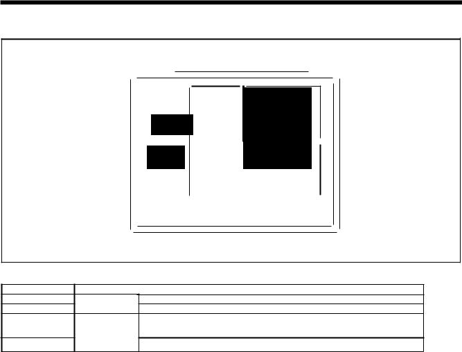
2. FUNCTION SETTINGS
2-5. Setting the work clamp mode
0 -X X·SCALE
OfCAUTION
o fvv-scALE
oE) SPEED
Ot!DiJCOUNTER
0 .1_ SPRIT No.
ill B!® ®~
- 88888
4556Q
The work clamp/button clamp operating mode can be switched as follows using the setting for memory switch No. 050.
Setting range
1
2
Single pedal
3
Two pedals
4
Setting items
Work clamp is raised automatically.
Work clamp is raised by depressing the foot switch.
Work clamp is raised automatically, then it is lowered by depressing the work clamp switch.
Work clamp is kept lifted while the work clamp pedal is depressing the work clamp switch.
10 |
KE-4300, BE-4380 |
|
From the library of: Superior Sewing Machine & Supply LLC |

2. FUNCTION SETIINGS
2-6. X-Y parallel movement for sewing patterns
The feed mechanism can be moved to the desired position and sewing patterns that have already been programmed can be moved in arallel vertical or horizontal directions.
1 |
|
|
|
|
|
|
|
|
|
|
|
|
|
|
|
|
|
Press the 1:::. or 'V key to select the program number, |
|
|||
|
|
|
|
|
|
|
|
|
|
|
|
|
|
|
|
|
|
and then depress the foot switch to the 2nd step. |
|
|||
|
|
|
|
~PROGRAM No. @ |
|
|
|
|
|
|
|
|
||||||||||
|
|
|
|
|
|
|
|
|
|
|
|
|||||||||||
|
|
|
|
|
|
|
|
|
|
|
• The feed mechanism will move to the home position. |
|
||||||||||
|
|
|
|
|
|
|
|
® |
|
|
|
|
|
|
|
|
|
2nd step |
|
|
|
|
|
|
|
|
|
|
|
|
|
|
|
|
|
|
|
|
|
|
|
|
4557Q4441Q |
|
|
|
|
|
|
|
|
|
|
|
|
|
|
|
|
|
|
|
|
|
|
|
||
|
|
|
|
|
|
|
|
|
|
|
|
|
|
|
|
|
|
|
|
|
|
|
|
|
|
|
|
|
|
|
|
|
|
|
|
|
|
|
|
|
|
|
|
|
|
|
|
|
|
|
|
|
|
|
|
|
|
|
|
|
|
|
|
|
|
|
||
2 |
|
|
|
|
|
|
|
|
|
|
|
|
|
|
|
|
|
While pressing the TEST key, press the V key. |
|
|||
|
|
|
|
|
|
|
|
|
|
|
|
|
|
|
|
|
|
• |
® |
|
|
|
|
|
|
|
|
|
|
|
|
|
|
|
|
|
|
|
|
|
|
|
|
||
|
|
|
|
|
|
|
|
|
|
|
|
|
|
|
|
|
|
|
|
|
||
|
|
|
|
|
|
|
olvv·SCALE |
|
|
|
|
|
|
|
|
|
|
|
|
|||
|
|
|
|
|
|
|
|
|
|
|
|
|
|
|
|
|
|
|
|
|||
|
|
|
|
|
|
|
o9SPEED |
|
|
|
|
|
|
|
|
• The parallel movement amount is displayed in the menu |
|
|||||
|
|
|
|
|
|
|
|
|
|
|
|
|
|
|
|
|
|
|
||||
|
|
, |
|
|
00COUNTEA |
|
|
|
|
|
|
|
display in mm units. |
|
|
|
||||||
|
|
~=- |
ol_SPRITNo. |
|
|
|
|
|
|
|
|
|
|
|
|
|||||||
|
|
|
|
-- |
|
|
|
|
|
|
|
|
|
|
|
|
||||||
|
|
|
|
• |
|
|
|
|
|
|
|
|
|
|
|
|
|
|
|
|
|
|
|
|
|
|
• |
|
|
|
B!®@~ |
|
|
|
|
|
|
||||||||
|
|
. |
888811 |
|
|
|
|
|
|
|
||||||||||||
|
|
|
|
|
|
|
|
|
|
|
|
|
|
|
|
|
|
|
|
|
|
|
|
|
|
|
|
|
|
|
|
|
|
|
|
TEST indicator lights |
|
|
|
4558Q4559Q |
|
||||
|
|
|
|
|
|
|
|
|
|
|
|
X-SCALE indicator flashes |
|
|
|
|
||||||
|
|
|
|
|
|
|
|
|
|
|
|
|
|
|
|
|
||||||
3 |
X scale |
parallel |
|
|
|
|
|
Y scale parallel |
Press the SELECT key so that the X-SCALE or Y-SCALE |
|
||||||||||||
|
|
|
|
|
indicator flashes. Select either indicator. |
|
||||||||||||||||
|
|
|
|
|
|
|
||||||||||||||||
|
movement mode |
|
|
|
|
|
|
movement mode |
|
|
|
|
|
|||||||||
|
:::'6,~X X-SCALE |
|
|
|
|
|
0 X X-SCALE |
|
|
|
|
|
||||||||||
|
/1 ..... |
|
|
|
|
|
|
..... |
|
|
|
|
|
|
|
|||||||
|
0 |
|
tv |
Y-SCALE |
|
|
|
|
|
:::'tf-:.t V Y-SCALE |
The feed mechanism moves by 0.05 mm each time the |
|
||||||||||
|
|
|
|
|
|
|
.A. or 'Y |
key is pressed. {If the movement is over 10 mm, |
|
|||||||||||||
|
|
|
|
|
|
|
|
|
|
|
/i\i |
|
||||||||||
|
|
|
|
|
|
|
|
,, ,, ,- |
|
|
|
|
the steps change to 0.1 mm.) |
|
|
|
||||||
|
|
|
|
|
|
|
|
|
|
|
|
* For X scale parallel movement mode, the relative |
|
|||||||||
|
|
|
|
|
|
|
|
|
|
|
|
movement of the needle is to the right when the .A. k~ |
|
|||||||||
|
|
|
|
|
|
|
|
|
|
|
|
is pressed, and the movement is to the left when the T |
|
|||||||||
|
|
|
|
|
|
|
|
u.u ::t |
key is pressed. |
|
|
|
||||||||||
|
|
|
|
|
|
|
|
|
|
|
|
|
mm |
* For Y scale parallel movement mode, the relative |
|
|||||||
|
|
|
|
|
.. |
|
T |
|
|
movement of the needle is to |
the back when the .A. |
|
||||||||||
|
|
|
|
|
|
~ |
|
|
|
|
key is pressed, and the movement is to the front when |
|
||||||||||
|
|
|
|
|
&a® |
® STEP |
the 'Y |
key is pressed. |
|
|
|
|||||||||||
|
|
|
|
|
STEP |
|
|
|
|
|
4566Q4561Q |
|
||||||||||
4 Ending parallel movement mode |
Press the TEST key. |
|
|
|
||||||||||||||||||
|
|
|
|
|
|
|
|
|
|
|
TEST indicator switches off |
|
|
|
|
|
||||||
|
|
|
|
|
|
|
|
|
|
|
|
|
|
|
|
|
|
|
|
|
|
|
Note:
• The feed mechanism cannot move to a place that would exceed the sewing area for the sewing pattern.
• If the program number or the vertical or horizontal ratio is changed, the movement amount that has been recorded will be
reset.
• Also once the power switch has been turned off, the amount of movement that has been stored in memory is reset. {However, when memory switch No. 465 is set to ON, the movement amount is recorded and is not reset.)
KE-430D, BE-438D |
11 |
From the library of: Superior Sewing Machine & Supply LLC

2. FUNCTION SETTINGS
2-7. Clearing saved data (Initialization)
Incorrect setting of data from sources such as memory switches can cause the sewing machine to operate incorrecUy. If this happens, you can foIIow the procedure beIow to initialize thesaved data toreturn the sewmq. mach"1ne to normaI operation.
|
|
Parameter No. |
|
|
|
|
|
|
|
|
|
|
|
|
|
|
|
|
|
|
|
|
|
|
|
Setting items |
|
|
|
|
||||
|
|
|
|
|
|
|
|
____ _[(~-~]_____ |
|
fl~~~!l..9 |
_<!1! |
_C!Q9J~9_n_~~~~~l}g_P!9..9r:.C!ITI~1~<?!:1}.P-~9~_1!1_!:'~·- |
?9_q |
_C!Q~~~t |
_________ |
|||||||||||||||||||
|
|
1 |
|
|
|
|
|
|
|
|
|
-... |
|
|
|
|
|
_ |
|
|
|
|
|
|
||||||||||
|
|
|
|
|
|
|
|
|
|
|
|
|
|
|
|
Clearing individual programs from program No. 200 and after |
|
|
|
|||||||||||||||
|
|
|
|
|
|
|
|
|
|
|
|
|
|
|
|
|
|
|
|
|
|
|
||||||||||||
|
|
2 |
|
|
|
|
|
|
|
[ |
MEM] |
|
|
Initializing memory switches. |
|
|
|
|
||||||||||||||||
|
|
3 |
|
|
|
|
|
|
|
[ |
ALL] |
|
|
Clearing or initializing all setting data (added sewing programs, memory switch |
||||||||||||||||||||
|
|
|
|
|
|
|
|
|
|
|
settings, user programs and cycle programs) |
|
|
|
|
|||||||||||||||||||
|
|
|
|
|
|
|
|
|
|
|
|
|
|
|
|
|
|
|
|
|
|
|
|
|
|
|||||||||
|
|
4 |
|
|
|
|
|
|
|
[ |
USE] |
|
|
Clearing user programs and cycle programs. |
|
|
|
|
||||||||||||||||
|
|
|
|
|
|
|
|
|
|
|
|
|
|
|
|
|
|
|
|
|
|
|
|
|
|
|
|
|
|
|
|
|
|
|
|
1 |
|
|
|
|
All indicators switch off |
|
|
|
|
|
|
|
|
While pressing the RESET key, tum on the power switch. |
|||||||||||||||||||
|
|
|
|
|
|
|
|
|
|
|
|
|
|
* Keep pressing the RESET key until the model name is |
||||||||||||||||||||
|
|
|
|
|
|
|
|
|
|
J |
|
|
|
|
|
|
|
|
|
|
|
|
|
|
|
|
|
|
|
displayed and the buzzer beeps once. |
|
|
|
|
|
|
|
|
|
r |
|
|
J |
|
|
|
|
|
|
|
|
|
|
|
)"-----._ |
|
|
|
|
||||||||||
|
|
|
|
|
|
|
|
|
|
|
|
|
|
|
|
|
|
|
|
|
|
|
~ |
|
|
|
|
|
|
|||||
|
|
|
|
|
|
|
|
|
|
|
|
|
|
|
|
|
|
|
|
|
|
|
|
|
|
|
|
|
|
|
|
|
|
|
|
|
|
|
|
|
|
|
|
|
|
|
|
... |
|
|
|
|
|
|
|
|
|
|
|
|
|
|
|
|
|
|
|
|
|
|
|
|
|
|
|
brothef |
|
|
r' |
- |
X·SCAI.E |
|
|
&PPOORIMNo.@ |
|
|
|
|
|
|
|
|
|
|
||||||||||
|
|
|
|
|
|
|
|
|
|
|
|
|
|
|
|
|
|
|
|
|||||||||||||||
|
|
|
|
|
|
|
|
|
0 |
|
|
( |
|
|
|
|
|
|
|
|
|
|
|
|||||||||||
|
|
|
|
|
|
O!CAUTION |
|
|
oJ |
|
Y Y·SCAI.E |
|
|
|
0 000 ® |
|
|
|
|
|
|
|
|
|
|
|||||||||
|
|
|
|
|
|
|
|
|
|
|
|
|
|
|
|
|
|
|
|
|
|
|||||||||||||
|
|
|
|
|
|
|
|
|
|
|
|
|
|
|
|
|
|
|
|
|
|
|||||||||||||
|
|
|
|
|
|
|
|
|
|
|
|
|
|
|
|
|
|
|
|
|
|
|
||||||||||||
|
|
|
|
|
|
•• |
|
|
ot |
|
?) SPEED |
|
|
|
|
|
|
|
|
|
|
|
|
|
||||||||||
|
|
|
|
|
|
|
|
|
|
|
|
|
|
|
|
|
.1\-1-1-1-1 r:--- |
|
|
|
|
|
|
|
|
|
||||||||
|
|
|
|
|
|
|
|
|
|
|
|
|
|
|
|
|
|
|
|
|
|
|
|
|
|
|
|
|||||||
|
|
|
|
|
- |
|
|
|
Ofll |
|
I!IICOUNTER -\\-- --- --I ,- |
|
|
|
|
|
|
|
|
|||||||||||||||
|
|
|
|
|
|
|
0 • |
|
LSPRIT NO;., |
. |
:: |
|
|
|
|
|
|
|
|
|
|
|||||||||||||
|
|
|
|
|
|
|
|
|
|
|
|
|
|
|
|
|
|
|
||||||||||||||||
|
|
|
|
|
|
|
|
|
~ |
|
|
~ |
|
|
|
' |
|
|
|
|
|
|
|
|
|
|
||||||||
|
|
|
|
|
|
|
|
|
1111!®'®! |
|
|
|
|
|
|
|
|
|
|
|
|
|||||||||||||
|
|
|
|
|
|
- 8888U |
|
|
|
|
|
• The parameter number will appear in the PROGRAM |
||||||||||||||||||||||
|
|
|
|
|
|
|
|
|
|
|
No. display, and the setting for that parameter will flash |
|||||||||||||||||||||||
|
|
|
|
|
|
|
|
|
|
|
|
|
|
|
|
|
|
|
|
|
|
|
|
|
|
|
|
|
|
in the menu display. |
|
|
|
|
|
|
|
- |
|
|
|
|
|
|
|
|
|
|
|
|
|
|
|
TEST indicator lights |
|
4562Q4421Q |
|||||||||||||
|
|
|
|
|
|
|
|
|
|
|
|
|
|
|
|
|
|
|
|
|||||||||||||||
|
|
|
|
|
|
|
|
|
|
|
|
|
|
|
|
|
|
|
|
Menu indicators switch off |
|
|
||||||||||||
|
|
|
|
|
|
|
|
|
|
|
|
|
|
|
|
|
|
|
|
|
|
|
|
|
||||||||||
|
2 |
|
|
|
|
|
|
|
|
|
|
|
|
|
|
|
|
|
|
|
|
|
|
|
|
|
|
|
|
Press the /i or V key to select the parameter number |
||||
|
|
|
|
|
|
|
|
|
|
|
|
|
|
|
|
|
|
|
|
|
|
|
|
|
|
|
|
|
|
for the item that is to be initialized. |
|
|
|
|
|
|
|
|
|
|
~PROGRAM No. @ |
|
|
|
|
|
|
|
|
|
|
|
|
|
|
||||||||||||||
|
|
|
|
|
|
|
|
|
|
|
|
|
|
|
|
|
|
|
|
|
||||||||||||||
|
|
|
|
|
|
|
|
|
|
|
|
|
® |
|
|
|
|
|
|
|
|
|
|
|
|
|
|
|
|
|
|
|
||
|
|
|
|
|
|
|
|
|
|
|
|
|
|
|
|
|
|
|
|
|
|
|
|
|
|
|
|
|
|
|
|
|
4557Q |
|
|
|
|
|
|
|
|
|
|
|
|
|
|
|
|
|
|
|
|
|
|
|
|
|
|
|
|
|
|
|
|
|
|
||
|
|
|
-seieC:t:i.i9inctividuafaC:idedsewfr19_P_ro9rams------------------------------------------------------------------------- |
|||||||||||||||||||||||||||||||
|
|
|
|
|
|
|
|
|
|
|
|
|
|
|
|
|
|
|
|
- |
|
LJ'''' |
lt you press the T key when parameter number "1" is |
|||||||||||
|
|
|
|
|
|
|
|
|
|
|
|
|
|
|
|
|
|
|
|
|
selected, the display will change from " SEW" to "-***". |
|||||||||||||
|
|
|
|
~PROGRAM No. |
|
|
|
|
|
|
|
|
|
|
|
|
|
(***is the added sewing program number.) |
|
|
||||||||||||||
|
|
|
|
@ |
|
|
|
|
|
|
|
|
Lf Lf |
|
|
|||||||||||||||||||
|
|
|
|
|
|
|
|
|
|
|
|
Press the A or T key to select the parameter number |
||||||||||||||||||||||
|
|
|
|
|
|
|
|
|
|
|
|
|
|
|
|
|
|
|
||||||||||||||||
|
|
|
|
|
|
|
|
|
IB3 |
|
|
|
|
|
|
|
|
|||||||||||||||||
|
|
|
|
|
|
|
|
|
|
|
|
|
|
|
|
|
||||||||||||||||||
|
|
|
|
|
|
|
|
® |
|
|
|
|
|
|
|
|
|
|
|
|
|
which is to be cleared of data. |
|
|
|
|
||||||||
|
|
|
|
|
|
|
|
|
|
|
|
|
~ |
|
|
|
|
|
|
|
|
|
|
|
|
|
|
|||||||
|
|
|
|
|
|
|
|
|
|
|
|
|
|
|
|
STEP |
|
|
|
|
|
|
|
|
|
|
|
|
|
|||||
|
|
|
|
|
|
|
|
|
|
|
|
|
|
|
|
|
|
|
|
|
|
|
|
|
|
|
|
|
|
|
|
|
4563Q |
|
|
|
|
|
|
|
|
|
|
|
|
|
|
|
|
|
|
|
|
|
|
|
|
|
|
|
|
|
|
|
|
|
|
||
|
|
|
|
|
|
|
|
|
|
|
|
|
|
|
|
|
|
|
|
|
|
|
|
|
|
|
|
|
|
|
|
|||
|
3 |
|
|
|
|
|
|
|
|
|
|
|
|
|
|
|
|
|
|
|
|
|
|
|
|
|
|
|
|
Press and hold the RESET key for 2 seconds or more. |
||||
|
|
|
|
|
|
|
|
|
|
|
|
|
|
|
|
|
|
|
|
|
|
|
|
|
|
|
|
|
|
* A long beep will sound and the data for the selected |
||||
|
|
|
|
|
|
|
|
|
|
|
|
|
|
|
|
|
|
|
|
|
|
|
|
|
|
|
|
|
|
item will be initialized. |
|
|
|
|
|
|
|
|
|
|
|
|
|
|
|
|
|
|
|
|
|
|
|
|
|
|
|
|
|
|
|
|
|
|
* The setting for only the item reinitialized will stop |
||||
|
|
|
|
|
|
|
|
|
|
|
|
|
|
|
|
|
|
|
|
|
|
|
|
|
|
|
|
|
|
flashing and illuminate steadily. |
|
|
|
|
|
|
|
|
|
|
|
|
|
|
|
|
|
|
|
|
|
|
|
|
|
|
|
|
|
|
|
|
|
|
|
|
|||
|
|
|
|
|
|
|
|
|
|
|
|
|
|
|
|
|
|
|
|
|
|
|
|
|
|
|
|
|
||||||
|
4 |
|
Ending data initialization mode |
|
|
|
|
|
|
|
|
Press the TEST key. |
|
|
|
|
||||||||||||||||||
|
|
|
|
|
• |
|
|
|
|
|
|
|
|
|
|
TEST indicator switches off |
|
|
|
|
|
|||||||||||||
|
|
|
|
|
|
|
|
|
|
|
|
|
|
|
|
|
|
|
|
|
|
|
||||||||||||
12 |
KE-430D, BE-438D |
|
From the library of: Superior Sewing Machine & Supply LLC |

2. FUNCTION SETTINGS
2-8. Checking the error history
The past error history can be checked by the following procedure.
4564Q
|
|
|
|
|
|
|
(2) |
|
|
|
|
|
|
||
|
|
|
|
|
|
|
|
|
|
|
|
|
|
|
|
|
|
|
|
|
|
|
|
|
|
|
|
|
|
|
|
|
|
|
|
|
|
|
|
|
|
|
|
|
|
||
|
|
|
|
|
|
|
|
|
|
|
|
|
|
|
|
|
|
|
|
0 |
- |
|
|
|
|
|
|
|
|
||
|
|
|
brother |
0 |
X X·SCALE |
|
|
|
|
|
|
(4) |
|||
|
|
|
|
|
|
|
|
|
|
||||||
|
|
|
|
O!CAUTION |
|
|
|
|
|
|
|
|
|
||
|
|
|
|
|
|
|
|
|
|
|
|
|
|
|
|
|
|
|
|
|
|
|
tVY·SCALE |
|
|
|
|
|
|
|
|
|
|
|
|
|
|
oi9SPEED |
|
|
|
|
|
|
|
|
|
|
|
|
|
|
|
|
|
|
|
|
|
|
|
||
|
|
|
|
|
|
|
|
|
|
|
|
|
|
|
|
|
|
|
|
|
|
|
|
|
|
|
|
|
|
|
|
|
|
|
|
|
|
|
|
|
|
|
|
|
|
|
|
|
|
|
|
|
|
OinmJlCOUNTER |
|
|
|
|
|
|
|||
(5) |
|
|
|
0 |
j_ SPRIT No. |
(3) |
|||||||||
|
|
|
|
|
|
|
|
|
|
|
|
|
|
|
|
|
|
|
|
|
|
|
|
|
|
|
|
|
|
|
|
|
|
|
|
|
|
|
|
|
|
|
|
|
|
|
|
TEST indicator lights
Menu indicators switch off
1. While pressing the 'fkey (1 ), tum on the power switch.
"Keep pressing the 'fkey (1) until the model name is displayed and the buzzer beeps once.
The error history number will be displayed in order in the PROGRAM No. display (2) and the error codes will be displayed in the menu display (3).
2. Press the ll or V key (4) to change the order of the error history number.
3.Press the TEST key (5) to return to the normal display. The sewing machine will switch to home position detection standby.
<o·1sp1ay examples>
Details |
PROGRAM No. display (2) |
Menu display (3) |
When there is no error history |
[000] |
[E---1 |
When error [E110] is displayed first |
[001] |
!E110] |
• The COUNTER indicator will light while the A key (6) is pressed, and the stitch number counter value when the error
occurred will be displayed in the PROGRAM No. display (2) and menu display (3) in units of 100 stitches.
KE-4300, BE-4380 |
13 |
From the library of: Superior Sewing Machine & Supply LLC
2. FUNCTION SETIINGS
2-9. Input checking method
Use this method to check for any malfunctions of the input keys at the operation panel, P.C.B.s and sensors, and for any broken cords or sensor position adjustments.
|
|
|
(2) |
|
|
|
|
|
|
|
|
|
|||||
|
|
|
|
|
|
|
|
|
|
|
|
|
|
|
|
|
|
|
|
|
|
|
|
|
|
|
|
|
|
|
|
|
|
|
|
|
|
brotJ'le( |
|
|
|
|
|
|
|
|
|
|
|
|
|
|
|
|
|
|
|
~~:: X X·SCALE |
|
|
|
|
|
|
|
|
|
|
|
||
|
|
|
|
|
|
|
|
|
|
|
|
|
|||||
|
|
|
|
,, |
|
|
|
|
|
|
|
|
|
|
|
|
|
|
|
O!CAUTION |
|
|
|
|
|
|
|
|
|
|
|
|
|
|
|
|
|
|
|
|
0 tYY·SCALE |
|
|
|
|
|
|
|
|
|
|||
-- |
|
|
oe SPEED |
|
|
|
|
|
|
|
|
|
|||||
|
|
|
|
|
|
|
|
|
|
||||||||
|
|
Oimm]COUNTER |
|
|
|
|
|
|
|
|
|
||||||
|
|
|
|
|
|
|
|
|
|
|
|||||||
|
|
|
|
|
|
|
|
|
|
||||||||
|
|
0 l_ SPRIT No. |
|
|
|
|
|
|
|
|
|
||||||
|
®liD |
|
|
|
|
|
|
|
|||||||||
|
8!(!) |
|
|
|
|
|
|||||||||||
|
STEP... |
|
|
|
|
|
|||||||||||
|
- |
|
|
|
|
|
|
|
|
|
|
|
|||||
|
|
|
88888 |
|
|
|
|
|
|
|
|
||||||
|
|
|
|
|
|
|
|
|
|
||||||||
|
|
|
|
|
|
|
|
|
|
|
|
|
|
|
|
|
|
(1)
(4)
(3) |
|
._, |
|
|
|
I I |
|
~fT\ |
us |
||
® STEP... |
|||
|
STEP\..!_) |
||
4565Q |
4566Q |
||
|
|
|
|
1. |
While pressing the ll |
key (1), turn on the power switch. |
|
|
* Keep pressing the ll |
key (1) until the model name is displayed and the buzzer beeps once. |
|
|
* The check code will be displayed in the PROGRAM No. display (2), and the input status will be displayed in the menu |
||
|
display (3). |
|
|
2. |
Press the ll key (1) or V key (4) to select a desired check code. |
||
|
If no operations are carried out for 5 seconds after moving to a check code, the check code and abbreviation will be |
||
|
displayed alternately in the PROGRAM No. display (2). |
||
3.Refer to the input check list to check the key and sensor responses.
4.When returning to normal operation, tum power off and then on again.
<Input check list >
PROGRAM |
No. display |
|
|
Menu display |
|
Check items and checking methods |
||||||
Check code |
Abbreviation |
|
|
Input status |
|
|||||||
|
|
|
|
|||||||||
[ |
1 ] |
|
[ orX] |
[ |
|
H] I [ |
|
L] |
X-feed shaft motor home position sensor position |
|||
|
|
|
Move the feed mechanism manuallv in the X-feed direction. |
|||||||||
|
|
|
|
|
|
|
|
|
|
|
||
[ |
2] |
|
[ EnX] |
[ -999]- [ |
|
999] |
|
X-feed shaft motor encoder counter value |
||||
|
|
|
Move the feed mechanism manuallv in the X-feed direction. |
|||||||||
|
|
|
|
|
|
|
|
|
|
|
||
[ |
3] |
|
[ orY] |
[ |
|
H] I [ |
|
L] |
Y-feed shaft motor home position sensor position |
|||
|
|
|
Move the feed mechanism manually in the Y-feed direction. |
|||||||||
|
|
|
|
|
|
|
|
|
|
|
||
[ |
4] |
|
[ EnY] |
[ -999]- [ |
|
999] |
|
Y-feed shaft motor encoder counter value |
||||
|
|
|
Move the feed mechanism manuallv in the Y-feed direction. |
|||||||||
|
|
|
|
|
|
|
|
|
|
|
||
[ |
5] |
|
[ orP] |
[ |
|
H] I [ |
|
L] |
Work clamp motor home position sensor position |
|||
|
|
|
Move the work clamp up manually. |
|||||||||
|
|
|
|
|
|
|
|
|
|
|
||
[ |
6] |
|
[ EnP] |
[-999]-[ |
|
999] |
|
Work clamp |
motor encoder counter value |
|||
|
|
|
Move the work clamp up manuallv. |
|||||||||
|
|
|
|
|
|
|
|
|
|
|
||
[ |
7] |
|
[ Enn] |
[ |
0]-[ |
|
180] |
|
Upper shaft 180 degree rotation signal |
|||
|
|
|
Tum the pulley by hand. |
|||||||||
|
|
|
|
|
|
|
|
|
|
|
||
14 |
KE-4300, BE-4380 |
|
From the library of: Superior Sewing Machine & Supply LLC |

2. FUNCTION SETTINGS
|
PROGRAM No. disolav |
|
|
|
|
Menu disolav |
|
|
Check items and checking methods |
|
|
|
|
|||||||||||||||||
Check code |
Abbreviation |
|
|
|
|
Input status |
|
|
|
|
|
|
||||||||||||||||||
|
|
|
|
|
|
|
|
|
|
|
|
|
||||||||||||||||||
[ |
8] |
[ |
UP] |
[ |
|
on] I [ |
oFF] |
Needle up signal |
|
|
|
|
|
|||||||||||||||||
|
Tum the pulley by hand. |
|
|
|
|
|
||||||||||||||||||||||||
|
|
|
|
|
|
|
|
|
|
|
|
|
|
|
|
|
|
|
|
|
|
|
|
|
|
|
||||
[ |
9] |
[ |
dn1 |
[ |
|
on 1/ [ |
oFF] |
Needle down signal |
|
|
|
|
|
|||||||||||||||||
|
Tum the pulley by hand. |
|
|
|
|
|
||||||||||||||||||||||||
|
|
|
|
|
|
|
|
|
|
|
|
|
|
|
|
|
|
|
|
|
|
|
|
|
|
|
||||
[ |
101 |
|
[val] |
[ |
0 1- [ |
3001 |
|
Power supply voltage |
|
|
|
|
|
|||||||||||||||||
|
|
Disolaved as %. |
|
|
|
|
|
|||||||||||||||||||||||
|
|
|
|
|
|
|
|
|
|
|
|
|
|
|
|
|
|
|
|
|
|
|
|
|
|
|
||||
[ |
11 1 |
|
[ PnL1 |
|
|
|
|
[ *] I [ |
|
oFF] |
Operation panel key input check |
|
|
|
|
|
||||||||||||||
|
|
|
|
|
|
The key name will be displaved while a kev is oressed. |
|
|
||||||||||||||||||||||
|
|
|
|
|
|
|
|
|
|
|
|
|
|
|
|
|
|
|
|
|
|
|
|
|||||||
|
|
|
|
|
|
|
|
|
|
|
|
|
|
|
|
|
|
|
|
|
|
|
|
|||||||
|
|
|
|
|
|
|
|
|
|
|
|
|
*ON displav |
|
|
|
Kevname |
|
|
|
|
|
||||||||
|
|
|
|
|
|
|
|
|
|
|
|
|
|
|
|
|
|
|
|
|
|
|
|
|
|
|
|
|
|
|
|
|
|
|
|
|
|
|
|
|
|
|
|
|
|
|
rESt 1 |
RESET kev |
|
|
|
|
|
||||||||
|
|
|
|
|
|
|
|
|
|
|
|
|
|
|
|
tESt 1 |
TESTkev |
|
|
|
|
|
|
|
||||||
|
|
|
|
|
|
|
|
|
|
|
|
|
|
|
|
tHrE 1 |
THREAD/CLAMP kev |
|
|
|
|
|
||||||||
|
|
|
|
|
|
|
|
|
|
|
|
|
|
|
|
tEn 1 |
TENSION/WIND kev |
|
|
|
|
|
||||||||
|
|
|
|
|
|
|
|
|
|
|
|
|
|
SELEl |
SELECTkev |
|
|
|
|
|
||||||||||
|
|
|
|
|
|
|
|
|
|
|
|
|
|
UP-M 1· |
.A kev |
|
|
|
|
|
|
|
||||||||
|
|
|
|
|
|
|
|
|
|
|
|
|
|
|
dn-M 1 |
T kev |
|
|
|
|
|
|
|
|||||||
|
|
|
|
|
|
|
|
|
|
|
|
|
|
|
|
|
F11 |
Function kev F1 |
|
|
|
|
|
|||||||
|
|
|
|
|
|
|
|
|
|
|
|
|
|
|
|
|
F21 |
Function kev F2 |
|
|
|
|
|
|||||||
|
|
|
|
|
|
|
|
|
|
|
|
|
|
r |
|
F31 |
Function kev F3 |
|
|
|
|
|
||||||||
|
|
|
|
|
|
|
|
|
|
|
|
|
|
r |
|
F41 |
Function kev F4 |
|
|
|
|
|
||||||||
|
|
|
|
|
|
|
|
|
|
|
|
|
|
|
|
CF] |
RIW kev |
|
|
|
|
|
|
|
||||||
[ |
121 |
|
[ FtA] |
[ |
|
0]-[ |
255] |
|
Foot switch analog value |
|
|
|
|
|
||||||||||||||||
|
|
|
Depress the foot switch. |
|
|
|
|
|
||||||||||||||||||||||
|
|
|
|
|
|
|
|
|
|
|
|
|
|
|
|
|
|
|
|
|
|
|
|
|
|
|
||||
[ |
131 |
|
[ CL11 |
[ |
|
on] I |
[ |
oFF) |
Work clamp switch 1st step |
|
|
|
|
|
||||||||||||||||
|
|
Depress the foot switch to the 1st step. |
|
|
|
|
|
|||||||||||||||||||||||
|
|
|
|
|
|
|
|
|
|
|
|
|
|
|
|
|
|
|
|
|
|
|
|
|
|
|
||||
[ |
141 |
|
[ CL2 I |
[ |
|
on] I |
[ |
oFF) |
Work clamp switch 2nd step (*) |
|
|
|
|
|
||||||||||||||||
|
|
Deoress the work clarno switch to the 2nd steo. |
|
|
|
|
||||||||||||||||||||||||
|
|
|
|
|
|
|
|
|
|
|
|
|
|
|
|
|
|
|
|
|
|
|
|
|
|
|||||
[ |
151 |
|
|
[ Stt] |
[ |
|
on] I |
[ |
oFF] |
Start switch |
|
|
|
|
|
|||||||||||||||
|
|
|
Depress the foot switch to the 2nd steo. |
|
|
|
|
|
||||||||||||||||||||||
|
|
|
|
|
|
|
|
|
|
|
|
|
|
|
|
|
|
|
|
|
|
|
|
|
|
|
||||
[ |
|
|
|
|
|
|
|
|
|
|
|
|
[--on] |
Stop switch (*) |
|
|
|
|
|
|||||||||||
16] |
[EMC] |
|
|
|
|
|
[on--] |
Press the stop switch. |
|
|
|
|
|
|||||||||||||||||
|
|
|
|
|
|
|
|
|
|
|
|
|
|
t----f |
|
|
|
|
|
|
|
|
|
|||||||
[ |
17] |
|
[ Hed] |
[ |
|
on] I |
[ |
oFF] |
Machine head switch |
|
|
|
|
|
||||||||||||||||
|
|
lilt back the machine head. |
|
|
|
|
|
|||||||||||||||||||||||
|
|
|
|
|
|
|
|
|
|
|
|
|
|
|
|
|
|
|
|
|
|
|
|
|
|
|
||||
|
|
18 |
|
|
|
EXE] |
|
|
|
|
on |
I |
|
|
oFF |
|
External input error detection-(*) |
|
|
|
|
|
||||||||
|
|
|
|
|
|
|
|
|
|
|
|
|
|
|
|
|
|
|
|
|
|
Thread nipper home position sensor |
|
|
|
|
|
|||
|
|
|
|
|
|
|
|
|
|
|
|
|
on] I |
[ |
|
|
|
Press the |
A key to move the thread nipper in the home position |
|||||||||||
[ |
191 |
[CAH] |
[ |
|
oFF] |
direction. |
T key to move the thread |
nipper |
in |
the |
retract |
|||||||||||||||||||
|
|
|
|
|
|
|
|
|
|
|
|
|
|
|
|
|
|
|
|
|
|
Press the |
||||||||
|
|
|
|
|
|
|
|
|
|
|
|
|
|
|
|
|
|
|
|
|
|
direction. |
|
|
|
|
|
|
|
|
|
|
|
|
|
|
|
|
|
|
|
|
|
|
|
|
|
|
|
|
|
|
Thread nipper retract position sensor |
|
|
|
|
|
|||
[ |
|
|
|
|
|
|
|
[ |
|
on] I |
[ |
|
|
|
Press the A key to move the thread nipper in the home position |
|||||||||||||||
201 |
|
[rEL] |
|
oFF] |
direction. |
T key to move the thread |
nipper |
in |
the |
retract |
||||||||||||||||||||
|
|
|
|
|
|
|
|
|
|
|
|
|
|
|
|
|
|
|
|
|
|
Press the |
||||||||
|
|
|
|
|
|
|
|
|
|
|
|
|
|
|
|
|
|
|
|
|
|
direction. |
|
|
|
|
|
|
|
|
|
|
21 |
|
|
|
in1 |
|
[ |
|
|
|
on I |
|
|
oFFl |
Option input -(IN1) |
|
|
|
|
|
|||||||||
|
|
22 |
|
|
|
in2 |
|
|
|
|
|
|
on |
|
I |
|
|
oFF |
|
Option input (IN2) |
|
|
|
|
|
|
||||
|
|
23 |
|
|
|
in3 |
|
|
|
|
|
|
on |
|
I |
|
|
oFF |
|
|
Option input (IN3) |
|
|
|
|
|
|
|||
|
|
|
|
|
|
|
|
|
|
|
|
|
|
|
|
|
|
|
|
|
|
|||||||||
|
|
24 |
|
|
|
in4 |
|
|
|
|
|
|
on |
|
I |
|
|
oFF |
|
|
Option input (IN4) |
|
|
|
|
|
|
|||
|
|
|
|
|
|
|
|
|
|
|
|
|
|
|
|
|
|
|
|
|
|
|||||||||
|
|
25 |
|
|
|
in5 |
|
|
|
|
|
|
on |
|
I |
|
|
oFF |
|
|
Option input (IN5) |
|
|
|
|
|
||||
|
|
|
|
|
|
|
|
|
|
|
|
|
|
|
|
|
|
|
|
|
||||||||||
|
|
26 |
|
|
|
rot |
|
|
|
|
|
|
on |
|
I |
|
|
oFF |
|
|
Rotating-type thread |
breakaae detector (*) |
|
|
|
|
|
|||
|
|
|
|
|
|
|
|
|
|
|
|
|
|
|
|
|
|
|
|
|
||||||||||
|
|
27 |
|
|
|
Fib |
|
|
|
|
|
|
on |
|
I |
|
|
oFF |
|
|
Fiber-type thread breakaae detector (*) |
|
|
|
|
|
||||
|
|
|
|
|
|
|
|
|
|
|
|
|
|
|
|
|
|
|
|
|
||||||||||
|
|
|
|
|
|
|
|
|
|
|
|
|
|
|
|
|
|
|
|
|
|
|
|
|
|
|
|
|
|
|
* Spare for the KE-430D and BE-4380.
KE-430D, BE-438D |
15 |
From the library of: Superior Sewing Machine & Supply LLC
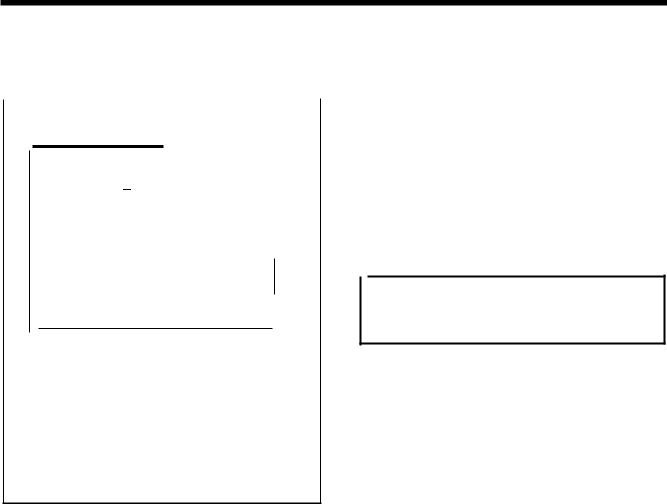
2. FUNCTION SETTINGS
2-10. Output checking method
Use the following procedure when checking for PCB-related failures, mechanism breakdown, and cord breakage. It can be checked as to whether signals that the CPU correctly output have been received.
4567Q
(2)
-O!CAUTIOH
•
•
•
~··~lit;d~TI.,.. ~III (4)
• ~
1---oDoLlr+(3)~~~I (1)
-~~~=:
a 8 8·==a:;:;::;:;F4=u:;:;::;:;:=--++-(5)
1.While pressing the V key (1 ), tum on the power switch.
•Keep pressing the V key (1) until the model name is
displayed and the buzzer beeps once.
The check code will be displayed in the PROGRAM No. display (2), and the abbreviated output name will be displayed in the menu display (3).
2.Press the li key (4) or V key (1) to select a desired check code.
3.Press the .... or T key (5) to check the operations for check codes 51 -54.
4.For check code 55 and after, depress the foot switch to the 2nd step.
The operation corresponding to the check code will be carried out while the foot switch is being depressed forward (each time the foot switch is depressed forward for check code 60).
5.When returning to normal operation, tum power off and then on again.
2nd step
4441Q
|
PROGRAM No. |
Menu display |
|
Function |
||||||||
|
|
display |
|
|||||||||
|
|
|
|
|
|
|
|
|
||||
|
Check code |
Abbreviation |
|
|
||||||||
|
[ |
51 ] |
[PM- X] |
When you press the • |
key, the work clamps move to the left. |
|||||||
|
When vou cress the T kev, the work clamcs move to the rioht. |
|||||||||||
|
[ |
52] |
[PM- y] |
When you press the A key, the work clamps move forward. |
||||||||
|
When vou press the T kev, the work clamcs move back. |
|||||||||||
|
|
|
|
|
|
|
|
|
|
|
||
|
[ |
53] |
[PM- F] |
When you press the • |
key, the work clamps rise. |
|||||||
|
When vou cress the T kev, the work clamps drop. |
|||||||||||
|
|
|
|
|
|
|
|
|
|
|
When you press the A key, the thread nipper moves toward the home |
|
|
[ |
54] |
|
[ CatH] |
position. |
|
||||||
|
|
When you press the T key, the thread nipper moves toward the retract |
||||||||||
|
|
|
|
|
|
|
|
|
|
|
position. |
|
|
|
|
551 |
|
r CLrl |
The valve for the right work clamp turns on.(*) |
||||||
|
|
|
561 |
|
CL-L |
The valve·for the left work clamp turns on. (*) |
||||||
|
|
|
571 |
|
r Foot |
The valve for the stepping foot turns on. (*) |
||||||
|
|
|
581 |
|
r FliP 1 |
The valve for the inner clamcina device turns on. (*) |
||||||
|
|
r |
591 |
|
rcool |
The valve for the needle cooler turns on.(*) |
||||||
|
|
|
|
|
--------- |
The tension release solenoid turns on. |
||||||
[ |
60] |
|
|
|
|
|
|
The LEOs on the panel illuminate in sequence, and then each of the seven |
||||
|
|
|
|
|
|
|
|
|
|
|
seoments of the PROGRAM No. display and menu display illuminate. |
|
|
|
|
61 |
|
|
CUt |
|
|
The thread trimmer solenoid turns on. |
|||
|
|
|
62 |
|
|
rEL |
|
|
|
|||
|
|
|
63 |
|
|
WiP |
|
|
The external wiper solenoid turns on. |
|||
|
|
|
64 |
|
|
StEP |
|
|
The steooina solenoid tums on. (*) |
|||
|
|
|
65 |
|
|
oP1 |
|
Option outout 1 tums on. |
||||
|
|
|
||||||||||
|
|
|
66 |
|
|
oP2 |
|
Option cutout 2 turns on. |
||||
|
|
|
67 |
|
|
oP3 |
|
|
Option cutout 3 turns on. |
|||
|
|
|
|
|
|
|||||||
|
|
|
|
|
|
|||||||
* Spare for the KE-4300 and BE-4380.
16 |
KE-4300, BE-4380 |
|
From the library of: Superior Sewing Machine & Supply LLC |
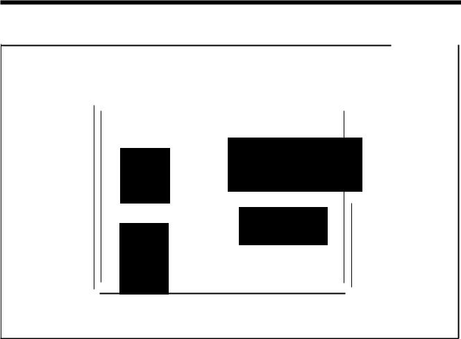
2. FUNCTION SETTINGS
2-11. Confirming software version
4568Q
(4)
|
|
|
|
|
|
|
|
|
|
|
|
|
|
|
|
|
|
|
|
|
|
|
|
|
|
|
|
|
|
|
brother |
|
|
|
|
|
|
|
|
|
|
|
|
|
|
|
0 |
X X·SCALE |
|
|
|
|
|
|
|
|
|
||
|
|
|
|
|
|
|
|
|
||||||
|
|
|
|
.._ |
|
|
|
|
|
|
|
(3) |
||
|
O!CAUTION |
|
|
tV V·SCALE |
|
|
|
|||||||
|
|
|
|
|
|
|
|
|
||||||
|
|
|
0 |
|
|
|
|
|
|
|||||
|
|
|
oE)SPEED |
|
|
|
|
|
|
|||||
|
|
|
|
|
|
|
|
|
||||||
|
|
|
|
|
|
|
|
|
|
|
||||
|
|
|
|
|
|
|
|
|
|
|
||||
|
|
|
Olmm)COUNTER |
|
|
|
|
|
(2) |
|||||
|
|
|
|
|
|
|
|
|||||||
(5 |
|
|
0 |
j_ SPRIT No. |
|
|
||||||||
|
|
|
|
|
|
|||||||||
|
|
|
|
|
|
|
||||||||
|
|
|
|
|
|
|
|
|||||||
|
|
|
|
-~(!) |
|
|
|
|
|
|
||||
|
|
|
|
STEP |
|
|
|
|
|
|
||||
|
|
|
|
|
|
|
|
|
(1) |
|||||
88888
TEST indicator lights
Menu indicators switch off
1.If you tum on the power while pressing the • key (1 ), the software version will be displayed in the menu display (2). *Keep pressing the • key {1) until the model name is displayed and the buzzer beeps once.
2.The PROGRAM No. display (4) will change as follows each time the li or V key {3) is pressed.
PROGRAM No. display (4) |
Software |
[ 1.Mn] |
Main CPU |
r2.Mtl |
Motor CPU |
r3.PL 1 |
Panel CPU |
3.Press the TEST key (5) to return to the normal display. The sewing machine will switch to home position detection standby.
KE-4300, BE-438D |
17 |
From the library of: Superior Sewing Machine & Supply LLC

3. USING CF CARDS
3. USING CF CARDS
3-1. Notes on handling CF cards (purchase at local re1ailers)
•Use only 32MB, 64MB, 128MB or 256MB CF cards.
•Do not disassemble or alt~r CF cards.
• Do not bend, drop, scratch or place heavy objects on top of the CF cards.
• Do not allow the CF cards to become wet, such as with water, oil, solvents, drinks or any other liquids.
• Do not use or store the CF cards in a locations exposed to strong static electricity or electrical interference.
• Do not use or store the CF cards in a locations exposed to vibrations or impacts, direct sunlight, extreme dust (or lint}, high temperatures, high humidity, severe temperature fluctuations, or strong magnetic forces (such as from speakers}.
•While data is being read in from or written to the CF cards, do not allow the machine to be exposed to vibrations or impacts, and do not attempt to remove the CF cards from the machine.
•Data on the CF cards may be lost or damaged due to some malfunction or accident. We recommend backing up important data.
• Only insert or remove CF cards while the machine power is turned off. |
. |
•The CF cards that you purchased is already formatted. We recommend that the CF cards not be reformatted.
•The recommended CF cards are commercially-available ones from SanDisk or HAGIWARA SYS-COM. CF cards from other manufacturers can be used, but different formatting methods may mean that reading or writing to such cards may not be possible.
For additional information, refer to the instruction manual included with the CF cards that you have purchased.
*This product is compatible with CF cards that have been formatted using the FAT16 method. Cards that have been formatted using the FAT32 method cannot be used.
* CF™ is a trademark of SanDisk Corporation.
*All other company and product names mentioned in this instruction manual are trademarks or registered trademarks of their respective companies. However, the explanations for markings such as TM are not clearly described within the text.
3-2. Structure of a CF card folder
\BROTHER\JSM\ISMSYS\ISM01 MN. MOT \BROTHER\ISM\ISMDAOO\ISMMSW.SEW (*1} \ISMUPG.SEW
\ISMHST.SEW
\ISMS0200.SEW
\ISMS0201.SEW
\ISMS0202.SEW
:Control program
:Memory switch data
:User program data
:Error log data
:Additional sewing data Program No. 200
:Additional sewing data Program No. 201
:Additional sewing data Program No. 202
I
*1 The underlined portion of the name of the \BROTHER\ISM\ISMDAQQ. folder for additional sewing data can be changed by changing the setting for memory switch No. 752. Change the folder name if you would like to store additional sewing data for different sewing machines on a single CF card.
4726Q
18 |
KE·430D,BE·438D |
|
From the library of: Superior Sewing Machine & Supply LLC |
|
|
|
|
|
|
|
3. USING CF CARDS |
|
|
|
|
|
|
|
|
|
3-3. Preparation for reading and writing data |
||||||
|
|
|
|
|
|
|
|
1 |
|
|
|
|
With the power turned off, insert the CF card into the CF |
||
|
|
|
|
|
|
slot. |
|
|
|
|
|
|
|
||
|
|
|
|
|
|
Note: |
|
|
|
|
|
|
|
• Make sure the CF card is facing the correct way. |
|
|
|
|
|
|
|
• The cover should be closed at all times except when |
|
|
|
m |
|
.~ |
|
the CF card is inserted and removed, otherwise dust |
|
0 |
~:.~,~,-- |
|
|
may cause trouble. |
|||
|
|
|
|
|
|
• If no valid data can be found, the CF media indicator |
|
|
|
|
|
|
|
will not illuminate. |
|
|
|
|
|
|
|||
4453Q
2 Tum on the power switch.
3 Switching to CF data read/write mode |
While pressing the TEST key, press the RNV key. |
• The mode number will be displayed in the PROGRAM No. display and the setting will be displayed in the menu display.
• The initial mode will be additional sewing data reading mode. (Refer to the read/write mode list.)
|
|
|
TEST indicator and CF media indicator li ht |
4574Q |
||||||
4 |
|
|
|
|
|
|
|
Press the 11 or V |
key to select the mode. |
|
|
|
~PROGRAM No. |
@® |
|
|
|
|
|||
|
|
|
,- |
,I |
|
|
|
|
||
|
|
|
|
|
|
|
|
|
4575Q |
|
|
|
|
|
|
|
|
|
|
||
|
|
|
|
|
|
|
|
|
||
[Read/write mode list] |
|
|
|
|
|
|
|
|||
|
|
|
|
|
|
|
|
|
||
PROGRAM No. |
Menu display |
|
Setting items |
|
||||||
display |
|
|
|
|||||||
|
|
|
|
|
|
|
|
|
||
r 1 |
|
|
[-SEd] |
|
Additional sewing data is read from the CF card. * |
|
||||
|
|
|
|
|
|
|
|
|
||
w2 |
|
|
SEd- |
|
|
Additional sewing data is written to the CF card. |
|
|
||
r3 |
|
|
-MEM |
|
|
Memory switch settings are read from the CF card. |
|
|||
w4 |
|
|
MEM- |
|
|
Memory switch settings are written to the CF card. |
|
|||
r5 |
|
|
[ -UPG] |
|
User programs are read from the CF card. |
|
|
|||
w6 |
|
|
[ UPG-] |
User programs are written to the CF card. |
|
|
||||
r7 |
|
|
[ -SyS] |
|
Control programs are read from the CF card |
and used to update the firmware |
|
|||
|
|
|
version. |
|
|
|||||
|
|
|
|
|
|
|
|
|
||
w8 |
|
|
[LoG- |
|
Error log data is written to the CF card. |
|
|
|||
*Additional sewing data that can be used by this product is data that has been created for the KE-4300/BE-4380.
KE·430D,BE·438D |
19 |
From the library of: Superior Sewing Machine & Supply LLC

3. USING CF CARDS
3-4. Reading additional sewing data
1 Selecting |
the "r 1''CF data read/write mode |
Press the RIW key. |
|
~PROGRAMNo. @ |
|
|
|
|
,- ,- I |
|
|
|
|||||
|
|
-JCO |
|
|
|
|||||||||
|
|
|
|
® |
|
c:afT\ |
® |
li!i!J |
• "-SEd" will change to" ALL". |
|||||
|
0[00 |
|
|
II+ |
|
|
||||||||
|
|
STEP\.!_) |
|
STEP |
4576Q |
|||||||||
|
|
|
|
,......, . ' |
|
|
|
|||||||
2 |
|
|
|
|
|
|
|
Press the ! or T key to select the program numbers |
||||||
|
|
|
|
|
|
|
|
• If" ALL" is displayed, all additional sewing data will be |
||||||
|
|
|
|
If L |
L |
|
|
|
(ALL, 200 - 999) that you would like to read. |
|||||
|
|
|
|
|
|
|
read. |
|||||||
|
la:tC!) |
|
II+ |
|
|
|
||||||||
|
|
|
|
|
|
|
||||||||
|
.. |
T |
|
limJ |
|
|
|
|
|
|||||
|
® STEP |
|
|
|
|
|
||||||||
|
STEP |
|
|
|
|
4577Q |
||||||||
3 |
|
|
|
|
|
|
|
|
|
|
|
|
Press the R/W key. |
|
|
|
|
|
|
|
|
|
|
|
|
|
|||
|
|
|
|
|
|
® |
|
|
|
|
|
|
II |
|
|
|
|
|
|
|
|
|
|
|
|
|
• The buzzer will sound and the selected sewing data will |
||
|
|
|
|
|
|
|
|
|
|
|
|
|
||
|
|
|
|
|
|
|
|
|
|
|
|
|
be loaded from the CF card and copied into the sewing |
|
|
|
|
|
|
|
|
|
|
|
|
|
|
machine'sinternal memory. |
|
|
|
|
|
|
|
|
|
|
|
While readin |
4498Q |
|||
|
|
|
|
|
|
|
|
|
|
|
|
|||
4 |
Ending .ode |
|
|
|
|
|
|
|
Press the TEST key. |
|
||||
|
|
|
|
|
|
|
Tum off the power switch, and then remove the CF card. |
|||||||
|
|
|
|
|
|
TEST indicator switches off |
|
|
||||||
3-5. Writing additional sewing data to the CF card |
||||||||||||||
|
|
|
|
|
|
|
|
|
|
|||||
1 |
Selecting the ''w2" CF data read/write mode |
|
|
Press the R/W key. |
||||||||||
|
|
|
|
|
|
|
|
,,-o- |
|
|
|
|
||
|
~PROGRAM No. |
|
|
,- - |
I |
|
|
|
|
|||||
|
|
|
|
|
|
|
|
|
|
|
|
|||
|
|
|
|
|
la:tC!) |
|
|
|
• "SEd-" will change to" ALL". |
|||||
|
|
|
|
|
|
|
|
|||||||
|
|
|
|
|
|
.. T |
|
|
|
|
|
|||
|
|
|
|
|
|
STEP |
|
|
|
|
|
|||
|
|
|
|
|
|
|
|
|
|
|
|
|
4578Q |
|
|
|
|
|
|
|
|
|
|
|
|
|
|
|
|
2 |
|
|
|
|
|
|
|
|
|
|
|
|
Press the ! or T key to select the program numbers |
|
|
|
|
|
1::1 |
I |
I |
|
|
|
(ALL, 200--999) that you would like to write. |
||||
|
|
|
|
|
|
|
• If" ALL" is displayed, all additional sewing data will be |
|||||||
|
|
|
|
If L |
L |
|
|
|
||||||
|
|
|
|
|
|
|
written. |
|||||||
|
|
la:tC!) |
|
|
II+ |
|
|
|
||||||
|
|
|
|
|
|
|
|
|
||||||
|
.. |
T |
|
ED |
|
|
|
|
|
|||||
|
® STEP |
|
|
|
|
|
||||||||
|
|
STEP |
|
|
|
|
4577Q |
|||||||
3 |
|
|
|
|
|
|
|
|
|
|
|
|
Press the RIW key. |
|
|
|
|
~PROGRAMNo. |
@ |
|
|
|
|
|
|
|
|
||
|
|
|
|
o~_@ |
|
|
|
|
|
The buzzer will sound and the selected sewing data |
||||
|
|
|
|
|
|
|
|
will •be copied from the internal memory onto the CF |
||||||
|
|
|
|
|
|
|
|
|
|
|
|
|
card. |
|
|
|
|
|
|
|
|
|
|
|
While writin |
4579Q |
|||
4 |
Ending |
read/write mode |
|
|
|
|
|
|
|
|
Press the TEST key. |
|||
|
|
• |
|
|
|
|
|
|
|
|
|
Turn off the power switch, and then remove the CF card. |
||
|
|
|
|
TEST indicator switches off |
|
|
||||||||
|
|
|
|
|
|
|
|
|
|
|
|
|
||
20 |
KE·430D, BE·438D |
|
From the library of: Superior Sewing Machine & Supply LLC |

3. USING CF CARDS
3-6. Reading memory switch data
1 |
Selecting the "r 3" CF data read/write mode |
|
|
|
|
|
|||||||||
|
|
|
|
|
|
|
|
-,,,-,, |
|
|
|
|
|||
|
|
|
~PROGRAMNo. |
@ |
|
|
'' |
, |
- |
|
|
|
|
||
|
|
|
|
|
|
|
~'T' |
- |
mm |
|
|
|
|
||
|
|
|
|
o[Eg) |
@ |
|
|
|
|
|
|
||||
|
|
|
|
|
|
~ |
|
|
|
|
|||||
|
|
|
|
|
STEP\!._) |
@ STEP |
|
|
|
|
|||||
|
|
|
|
|
|
|
|
|
|
|
|
|
4580Q |
|
|
2 |
|
|
|
|
|
|
|
|
|
|
|
Press the R/W key. |
|
|
|
|
|
|
|
|
|
|
|
|
|
|
|
II |
|
||
|
|
|
|
|
|
|
|
|
|
|
|
|
|
||
|
|
|
|
|
|
® |
|
|
|
|
• The buzzer will sound and the selected memory switch |
|
|||
|
|
|
|
|
|
|
|
|
|
data will be loaded from the CF card and copied into |
|
||||
|
|
|
|
|
|
|
|
|
|
the sewing machine'sinternal memory. |
|
||||
|
|
|
|
|
|
|
|
|
While reading |
|
4498Q |
|
|||
|
|
|
|
|
|
|
|
|
|
|
|
||||
|
|
|
|
|
|
|
|
|
|
|
|
|
|
||
3 |
,.. |
|
|
|
|
|
|
When " End" is displayed, the operation is complete. |
|
|
|||||
|
|
|
|
~PROGRAMNo |
@ |
|
|
|
|
Turn off the power switch, and then remove the CF card. |
|
|
|||
|
|
|
|
|
|
|
|
|
|
|
|
||||
|
|
|
|
~o:~''"IM.J-:;,:;:1o!X'Ilf!J |
® |
|
|
|
|
|
|
|
|
||
|
|
|
|
|
|
|
|
|
|
|
|
|
458IQ |
|
|
3-7. Writing memory switch data to the CF card |
|||||||||||||||
|
|
|
|
|
|
|
|
||||||||
1 |
Selecting the ''w4" CF data read/write mode |
|
|
|
|
|
|||||||||
|
|
|
|
|
|
|
,, ,- '' |
|
|
|
|
|
|||
|
|
|
~PROGRAMNo. |
@ |
|
|
|
|
|
|
|
||||
|
|
|
|
|
|
|
|
liCit - |
|
|
|
|
|||
|
|
|
|
|
|
|
G!i.B(!) |
|
mm |
|
|
|
|
||
|
|
|
|
o!Hl |
@ |
|
~ |
|
T |
|
~ |
|
|
|
|
|
|
|
|
|
STEP |
|
@ STEP |
|
|
|
|
||||
|
|
|
|
|
|
|
|
|
|
|
|
|
4582Q |
|
|
|
|
|
|
|
|
|
|
|
|
|
|
|
|
|
|
2 |
|
|
|
|
|
|
|
|
|
|
|
Press the RIW key. |
|
||
|
|
|
|
|
|
|
|
|
|
|
|
II |
|
||
|
|
|
|
|
|
|
|
|
|
|
|
• The buzzer will sound and the memory switch data will |
|
||
|
|
|
|
|
|
|
|
|
|
|
|
be copied from the internal memory onto the CF card. |
|
||
|
|
|
|
|
|
|
|
|
|
While writin |
|
4579Q |
|
||
|
|
|
|
|
|
|
|
|
|
|
|
|
|
||
3 |
Ending read/write mode |
|
|
|
|
|
|
Press the TEST key. |
|
|
|||||
|
|
|
|
• |
|
|
|
|
|
|
|
Turn off the power switch, and then remove the CF card . |
|
||
|
|
|
|
|
|
TEST indicator switches off |
|
|
|
|
|||||
|
|
|
|
|
|
|
|
|
|
|
|
|
|
|
|
KE·430D, BE·438D |
21 |
From the library of: Superior Sewing Machine & Supply LLC

3. USING CF CARDS
3-8. Reading user program data
1 Selecting the "r 5" CF data read/write mode
~PROGRAM |
No. @ |
' ,10 ,- |
|
|
-. Lf I |
U |
|
|
|
|
|
|
|
|
|
.. T |
|
... |
|
|
||
|
|
|
|
|
|
|
|
IDa(!) |
® |
B!J |
|
|||
|
|
|
|
|
|
|
|
STEP |
STEP |
4583Q |
||||
|
|
|
|
|
|
|
|
|
|
|
|
|
|
|
|
|
|
|
|
|
|
|
|
|
|
|
|
|
|
2 |
|
|
|
|
|
|
|
|
|
|
|
Press the RNV key. |
|
|
|
|
|
|
|
@ |
|
|
|
11 |
|
||||
|
|
|
|
|
|
|
|
|
|
|
||||
|
|
|
|
|
|
|
® |
|
|
|
• The buzzer will sound and the selected user program |
|||
|
|
|
|
|
|
|
|
|
|
data will be loaded from the CF card and copied into |
||||
|
|
|
|
|
|
|
|
|
|
the sewing machine'sinternal memory. |
4498Q |
|||
|
|
|
|
|
|
|
|
|
|
|
While readin |
|||
|
|
|
|
|
|
|
|
|
|
|
||||
|
|
|
|
|
|
|
|
|
|
|
|
|||
3 |
|
|
|
|
|
|
|
|
|
|
|
When " End" is displayed, the operation is complete. |
||
|
~PROGRAMNo. |
@ |
|
|
|
Turn off the power switch, and then remove the CF card. |
||||||||
|
|
|
|
|
|
|||||||||
|
|
|
|
|
|
Note: |
|
|||||||
|
|
|
111111AO';';:;:]O~ |
® |
|
|
|
read the |
||||||
|
|
|
|
|
|
|
additional sewing data. You will need to |
|||||||
|
|
|
|
|
|
|
|
|
|
|
|
|
If additional sewing data has been incorporated into a |
|
|
|
|
~1, |
|
|
|
|
|
|
|
|
user program, this operation will not |
read the |
|
|
|
|
|
|
|
|
|
|
|
|
|
|||
|
|
|
|
"IM.J |
t!RJ |
|
|
|
|
|
|
additional sewing data separately. (Refer to "3-4. |
||
|
|
|
|
|
|
|
|
|
|
|
|
|
Reading additional sewing data".) |
4581Q |
|
|
|
|
|
|
|
|
|
|
|
|
|
||
|
|
|
|
|
|
|
|
|
|
|
|
|
|
|
|
|
|
|
|
|
|
||||||||
3-9. Writing user program data to the CF card |
|
|||||||||||||
|
|
|
|
|
|
|
|
|||||||
1 |
Selecting the ''w6" CF data read/write mode |
|
|
|
||||||||||
|
|
|
|
|
|
|
|
|
|
|
|
|
||
|
|
~PROGRAMNo. |
@ |
|
|
|
|
|
|
|
|
|||
|
|
|
|
|
|
|
|
|
|
|
|
B!J |
|
|
|
|
|
|
oi!Il |
@ |
|
|
|
|
® |
STEP... |
4584Q |
||
|
|
|
|
|
|
|
|
|
|
|
|
|
||
2 |
|
|
|
|
|
|
|
|
|
|
|
Press the RMI key. |
|
|
|
|
|
|
|
|
|
|
|
|
|
|
11 |
|
|
|
|
|
|
|
|
|
|
|
|
|
|
• The buzzer will sound and the user program data will be |
||
|
|
|
|
|
|
|
|
|
|
|
|
copied from the internal memory onto the CF card. |
||
|
|
|
|
|
|
|
|
|
|
|
While writin |
4579Q |
||
3 |
Ending read/write mode |
|
|
|
|
|
Press the TEST key. |
|
||||||
|
|
• |
|
|
|
|
|
|
|
Tum off the power switch, and then remove the CF card. |
||||
|
|
|
|
|
|
|
|
|
|
|
|
|||
|
|
|
|
|
|
|
|
TEST indicator switches off |
|
|||||
22 |
KE-4300, BE-4380 |
|
From the library of: Superior Sewing Machine & Supply LLC |
3. USING CF CARDS
3-10. Updating the control programs
1 Selecting the "r 7" CF data read/write mode
~PROGRAM No. @ |
,- I I ,- |
||
-_:;.:.-; |
|
||
® |
|
® |
li!.l!l |
|
STEPIll+ |
||
Press the RM/ key.
•After a set period of time, "-SyS" will change to" vEr'', and then the version number of the control program that is stored on the CF card will be displayed.
4585Q
2 |
|
Press the RM/ key. |
@
@
I,,,,
f. LJ u
•" P" will flash in the PROGRAM No. display and the control program update will start.
Note:
If the filename and folder name for the control program are not correct, error "E421" will be displayed.
~~ |
|
|
||
STEP\!_) |
|
|
||
|
|
|
|
4586Q |
|
|
|
|
|
3 |
|
|
|
When " End" is displayed, the operation is complete. |
|
|
|
|
Turn off the power switch, and then remove the CF card. |
|
~PROGRAMNo. |
@ |
Note: |
|
|
liBI |
® |
• The version upgrading takes about 3 minutes. (fhe |
|
|
time taken varies depending on the CF card |
|||
|
~l.. |
|
||
|
|
manufacturer and the card'scapacity.) |
||
|
|
|
||
|
...o~;:::1 |
Orx-. |
• Never remove and reinsert the card or tum off the |
|
|
"LM..I |
LfltJ |
|
power switch while reading is in progress. |
|
|
|
|
458IQ |
<Recovery procedure if an error occurs during version updating>
If the version update does not complete normally because of a problem such as a power failure, the sewing machine will not operate correctly.
If this happens, carry out the following recovery procedure.
1.Insert the CF card containing the control program data into the CF card slot.
2.Turn on the power switch.
3.When " End" is displayed, the operation is complete. Tum off the power switch, and then remove the CF card.
KE·430D, BE·438D |
23 |
From the library of: Superior Sewing Machine & Supply LLC
 Loading...