


LK3-B438-2
PARTS
From the library of: Superior Sewing Machine & Supply LLC
BOOK
FOR
BROTHER LK3-B438-2,-3,-4
( P438202 )
High
•
--
Speed
•
BROlHER
Lock
•
Stitch
-··
Button
•
Sewing
Machine
BROTHER
INDUSTRIES,
NAGOYA, JAPAN
LTD.
Notes for using this parts book
From the library of: Superior Sewing Machine & Supply LLC
I. This
2.
3.
4. This
5.
book
is
applicable to sewing machines which have the same plate number as
shown
If
No." column, refer to the different parts list
The symbol I
available for supply.
the parts can be ordered as
Assembly No.
Parts are subject to changes in design without prior notice.
on
the cover
the symbol I I
~I
book
was prepared based
of
this
If,
however, there
book
is
found in the
in the
"Parts
an
assembly. Please, therefore, order by using the
on
(or correction sheet).
"Parts
No." column indicates that the Parts
is
a number in the "Assembly No." column,
information available in April,
No." column
on
page
16.
or
the "Assembly
1981.
is
not
Anmerkungen zum Gebrauch dieses Stucklistebuches
I. Dieses Buch bezieht sich
wie
auf
diesem Buchumschlag ( oder
2.
Dieses Zeichen I I in der Spalte
sembly No. (Geratesatznummer)" verweist
16.
3.
Dieses Zeichen I
nicht lieferbar ist. Wenn Jedoch in der Spalte "Geratesatznummer" eine Nummer
steht, kann dieser Teil als ein Gerateteilsatz bestellt werden. Bestellen Sie daher
bitte mit dieser Geratesatznummer.
4. Dieses Buch basiert
5.
Modellanderungen sind vorbehalten.
~I
auf
die Nahmaschinen mit derselben Kennungsnummer
auf
dem Korrekturblatt).
"Parts
auf
in der Spalte "Teilnummer" bedeutet,
auf
den Informationen vom April,
No. (Teilnummer)" oder "As-
die Gesonderte Stiickliste
daB
dieser Teil
1981.
auf
Seite

Notes sur l'utilisation de ce manuel de pieces detachees
From the library of: Superior Sewing Machine & Supply LLC
I. Ce manuel est destine
Ia
montre sur
2.
Si
le
symbole I I
Ia
dans
pieces annexe page
3.
Le
etre fournie. Si, dans
Ia
toute commande, veuillez specifier
4.
Ce manuel a ete fait d'apres
5.
Les pieces peuvent etre sujettes a des modifications sans preavis.
colonne "Assembly No.
symbole
piece peut etre commandee com
couverture de
I~
aux
16.
I dans
Ia
colonne
machines a coudre ayant
ce
manuel (ou sur
se
trouve dans
(No
jeu
Ia
colonne "No de piece'' signifie que Ia piece ne peut
"No
jeu de pees",
me
le
les
renseignements valables
Ia
colonne
de pees)", veuillez vous referer a
faisant partie d'un jeu de pieces. Done,
No
de jeu de pieces.
le
meme numero de plaque
Ia
feuille de corrections).
"Parts
il
y a un numero de nomenclature,
No. (N° de piece)" ou
Ia
au
mois de Avril
liste de
pour
1981.
Notas para usar este Libro de Piezas
I. Este libro sirve para todas las maquinas de coser que llevan
Ia
que
se
identificaci6n que
2.
De haber un sinbolo I I
del"
columna
separada de
3.
El simbolo
quiere decir que no
Ia
columna del "Numero de Juego",
en
Por
lo tanto, sera mejor hacer
4. Este libro ha sido compilado basandose en los datos de que se disponia en abril de
1981.
5.
Las piezas quedan sujetas a cam bios. de disefio sin aviso previo.
Assembly No. (Numero de Juego)", habra que mirar
Ia
pagina 16.
1~1
se
puede ver en
, que
se
dispone de dicha pieza sola. Cuando, empero, hay un numero
el
pedido recurriendo al numero deljuego respectivo.
Ia
tapa
junto
al
"Parts
encuentra en
se
podra ordenar la pieza con todo eljuego.
de este libro ( o en Ia hoja de erratas).
No. (Numero de Pieza)" o en Ia
Ia
columna del "Numero de Pieza",
Ia
misma placa de
Ia
lista de piezas
CONTENTS
From the library of: Superior Sewing Machine & Supply LLC
A.
Machine Body ........................................................................ I
B.
Upper Shaft · Lower Shaft and Needle Bar Mechanism ....... 2
C.
Pulley and Clutch
D. Power Lift and Clutch Mechanism ........................................ 4
E.
Presser Arm Mechanism ........................................................ 5
F. Feed Mechanism .................................................................... 6
G.
Vertical Shaft Mechanism...................................................... 7
H.
Work Clamp and Thread Wiper Mechanism......................... 8
J.
Thread Trimming and Thread Nipper Mechanism ................ 9
K.
Bobbin Winder and Threading Mechanism ...........................
L.
Oil Pan . . . . . . . .
M.
Lubrication ............................................................................
Z.
Accessories
..
Mechanis~
.. . ..
. . . . . . . . ..
. . . . . . . ..
..
. . . . . . . .. .
............................................... 3
..
..
. . . . . . . . . . . . . . . . . . . . . . . . .
..
. .. . . .. . . .
..
. . . . .. . . . . . . . . . . . .
..
. . . . . .
..
. . .
..
. .
..
. . . . . .
..
. . . . . . . . . .
.. . ..
..
10
. . . . I 1
12
.. . . I 3
a. Special
b.
Shank Attachment-Device (Special order parts) .......................
DIFFERENT
INDEX ...........................................................................................
Order Parts . . . . . . .. . . ... . . .. ... .. . .. . .
PARTS LIST.........................................................
..
. .. . . . . . . . . . . . . . . . . . . . . . . . .
..
. . . .
..
. . .
14
15
16
I8
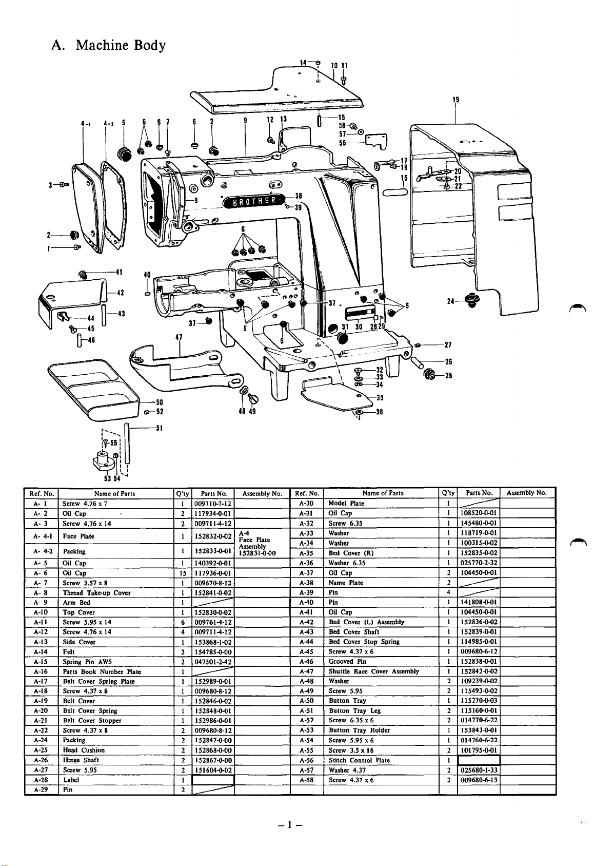
A. Machine Body
From the library of: Superior Sewing Machine & Supply LLC
4-t
__
---!
~----
9
1 l
!'~
I
15
o-5a~
57
@CJ
56
19
Ref. No.
A- 1
A- 2
A- 3
A- 4-1
A- 4-2
5
AA- 6
A- 7
A- 8
A- 9
A-10
A-ll
A-12
A-13
A-14
A-15
A-16
A-17
A-18
A-19
A-20
A-21
A-22
A-24
A-25
A-26
A-27
A-28
A-29
.,
r51
~1t
Name
4.76
Screw
Oil
Cap
Screw
4.76 x 14
Face
Plate
Packing
Oil Cap
Oil Cap
3.57
Screw
Thread
Take-up Cover
Arm Bed
Top
Cover
5.95 x 14
Screw
4.76 x 14
Screw
Side Cover
Felt
Spring Pin A
Parts Book
Belt Cover Spring Plate
Screw
4.37
Belt Cover
Belt
Cover
Belt Cover
Screw
4.37
Packing
Head Cushion
Shaft
Hinge
Screw 5.95
Label
Pin
53 54
of
x 7
x 8
WS
Number
x 8
Spring
Stopper
x 8
1
'
Parts
Plate
Q'ty
009710-7-12
1
117934-D-DI
2
009711-4-12
2
152832-Q-Q2
I
152833-D-D1
1
140392-o-ol
I
IS
117936-o-01
I
009670-8-12
152841-D-02
I
I
152830-o-02
I
----
009761-4-12
6
4
009711-4-12
153868-1-02
I
t547ss-o-oo
2
047501-2-42
2
I
I
152989-0-01
009680-8-12
1
1
152846-o-02
I 52848-D-DI
1
152986-0-01
1
009680-8-12
2
1 52847-o-oo
2
1
2
1
2
151604-o-02
2
1
2
Parts No.
Assembly No.
A-4
Face
Assembly
152831-Q.OO
----
s 2868-o-oo
52867-0·00
Plate
Ref. No.
A-30 Model Plate
Oil
A-31
A-32
A-33
A-34
A-35
A-36
A-37
A-38 Name Plate
A-39
A-40
A-41 Oil Cap
A-42
A-43
A-44 Bed Cover
A-45
A-46
A-47
A-48
A-49 Screw 5.95
A-SO
A-51
A-52
A-53
A-54
A-SS Screw 3.5 x 16
A·56
A-57 Washer
A-58 Screw
Cap
Screw
6.35
Washer
Washer
Bed Cover
Washer 6.35
Oil Cap
Pin
Pin
Bed Cover (L) Assembly
Bed Cover
4.37
Screw
Grooved Pin
Shuttle
Race Cover Assembly
Washer
Button
Tray
Button
Tray
Screw
6.35
Button
Tray
Screw 5.95 x 6
Stitch
Control
4.37
4.37
Name
(R)
Shaft
Stop
x 6
Leg
x 6
Holder
x 6
of
Spring
Plate
Parts
Q'ty
Parts No.
1
1
10852D-o-DI
----
145480-o-o1
1
1
118719-D-DI
1 10031S-o-o2
I 152835-D-D2
02577o-2-32
I
104450-Q-Q1
2
2
4
----
I 141808-D-D I
----
104450-o-ol
I
I 152836-o-o2
1 152839-D-Q1
1 114985-o-o1
009680-6-12
I
I 1S2838-o-o1
I
IS2842-o-o2
2 109239-o-o2
2 115493-o-02
1 11527o-o-D3
11516o-o-DI
2
014770-6-22
2
1
153843-o-ol
014760-6-22
1
2 101795-o-01
1
025680-1-33
2
2 009680-6-13
Assembly No.
----
-1-
10
From the library of: Superior Sewing Machine & Supply LLC
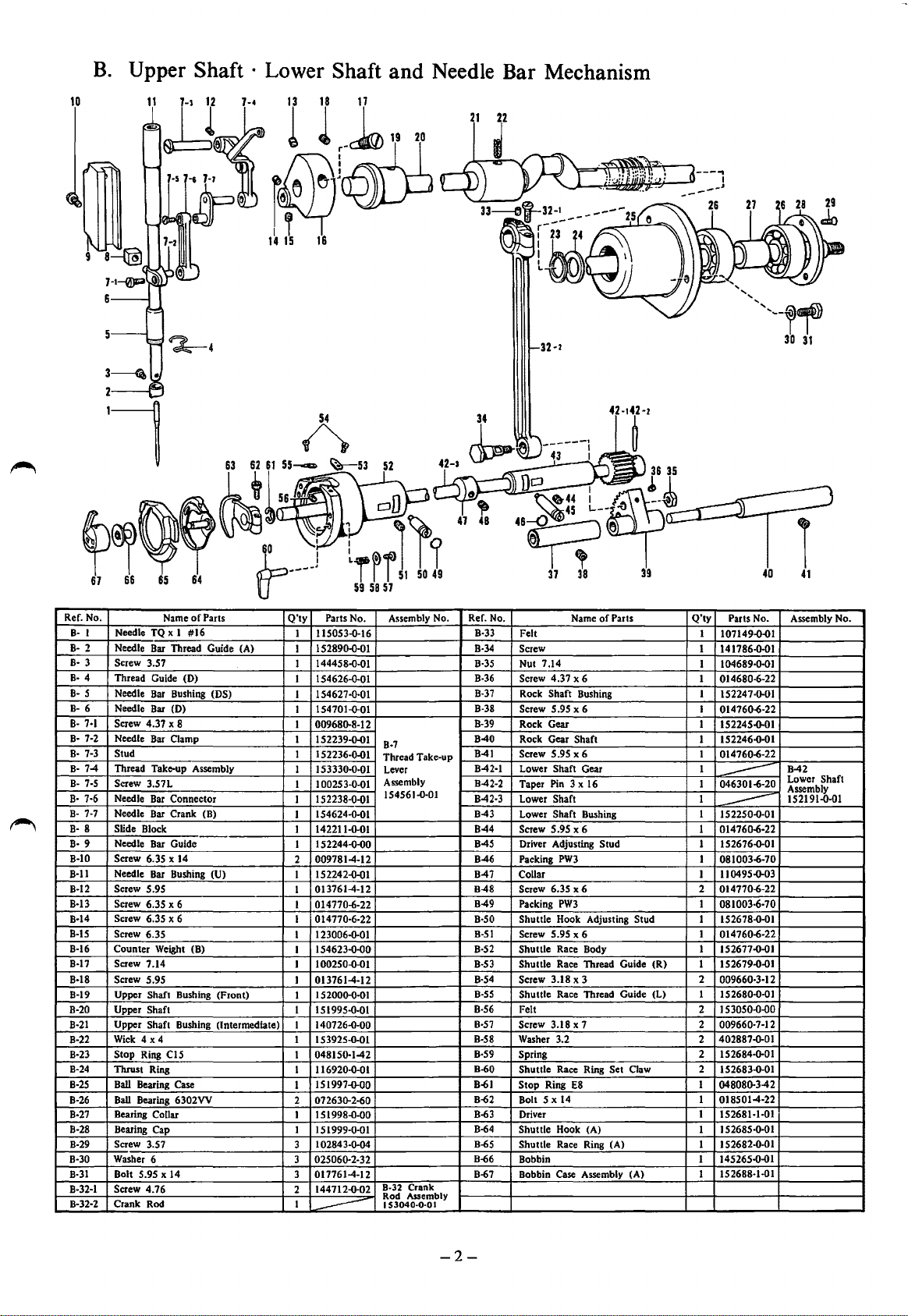
B.
Upper Shaft · Lower Shaft and Needle
Bar
Mechanism
Ref. No.
Needle TQ x I
B· I
Needle Bar Thread Guide (A)
B·
2
B· 3 Screw 3.57
Thread Guide (D)
B·
4
B-
5
Needle
B-
6 Needle
B-
7·1
Screw 4.37 x 8
Needle Bar Clamp
B· 7·2
Stud
B·
7-3
Thread Take-up Assembly
B·
7-4
Screw
B· 7·5
B·
7·6 Needle Bar Connector
Needle Bar Crank (B)
B·
7·7
Slide Block
B·
8
Needle Bar Guide
9
B·
B-10
Screw 6.35 x 14
Needle Bar Bushing (U)
B·ll
B-12
Screw 5.95
B-13
Screw 6.35 x 6
Screw 6.3S x 6
B-14
B-15
Screw 6.3S
B-16
Counter Weight (B)
B-17
Screw 7.14
B-18
Screw 5.95
Upper Shaft Bushing (Front)
B-19
B-20
Upper Shaft
B-21
Upper Shaft Bushing (Intermediate)
Wick 4 x4
B-22
B·23 Stop
B-24
Thrust Ring
Ball
B-25
B-26
Ball
B-27
Bearing Collar
B-28
Bearing Cap
B-29
Screw 3.S7
B-30
Washer 6
B-31
Bolt 5.95 X 14
8·32-1 Screw
Crank Rod
8·32·2
Name
Bar
Bar
3.S7L
Ring CIS
Bearing Case
Bearing 6302VV
4.76
of
Parts
#16
Bushing (DS)
(D)
Q'ty
Parts No. Assembly No.
1 115053-()-16 B·33 Felt
152890-()-01
1
144458.0-01
1
I 154626-0.01
154627-0.01
I
154701-()-01
I
I 009680.8-12
I S 2239.0.01
I
1
152236-0.01
153330-0-01
1
1
100253-0-01
1
152238-0-01
154624-0-01
1
142211-()-01
1
152244.0.00
1
009781-4-12
2
152242-0.01
I
013761-4-12
I
I 014770-6-22
I 014770·6-22
123006-()-01
1
154623.0.00
I
1002S0.0.01
1
I 013761-4-12
2000.0·0 1
IS
1
I IS1995.0-0I
I 140726-0-00
I IS 3925-0-01
048150.1-42
I
I 116920.0.01
ISI997-o-oo
I
2 072630.2-60
I 1 5 1998-0-00
151999-o-O 1
1
102843-o-04
3
025060.2-32
3
017761-4-12
3
144712-()-02
2
1
B-7
Thread Take-up
Lever
Assembly
154561-0·01
B-32
Crank
Rod Assembly
I
53040·0·01
Ref. No.
B-34
B-35
B-36
B-37
B-38
B-39
B-40
B-41
B-42·1 Lower Shaft Gear
B-42·2
B-42-3
B-43
B-44
B-45
B-46
B-47
B-48 Screw 6.3S x 6 2 014770-6-22
B-49
B·SO
B-51
B-52
B-53
B-54
B-55
B-56
8·57 Screw
B-58
B-59
B-60 Shuttle
B-61
B-62
B-63
B-64
B-6S
B-66
B-67
----
of
Parts
Name
Screw
Nut 7.14
Screw 4.37 x 6 1
Rock Shaft Bushing I
Screw 5.95 x 6 I
Rock Gear 1 152245-()-01
Rock Gear Shaft 1 152246.0.01
Screw 5.95 x 6
Taper Pin 3 x 16
Lower
Shaft
Lower Shaft Bushing I 152250-0-01
Screw 5.95 x 6 1 014760-6-22
Driver Adjusting Stud 1 152676-()-01
Packing
PW3
Collar
Packing
PW3
Shuttle Hook Adjusting Stud I 152678-()-01
Screw S.9S x 6 1 014760-6-22
Shuttle Race Body 1 152677-0.01
Shuttle Race Thread Guide (R) 1 1S2679.0-0I
Screw 3.18 x 3 2
Shuttle Race Thread Guide (L) 1 152680.0-01
Felt 2 I S 3050-0-00
3.18 x 7 2 009660-7-12
Washer 3.2 2
Spring
Race Ring Set Claw 2
Stop Ring E8
Bolt
5 x 14 1 018SOI-4-22
Driver
Shuttle Hook (A)
Shuttle Race Ring (A)
Bobbin 1 145265.0.01
Bobbin Case Assembly (A) 1
Q'ty
Parts No.
1
107149.0·01
1 141786-()-0 1
04689-0.01
1 1
014680-6-22
152247-0.01
014760-6-22
014760-6-22
1
1
046301-6-20
1
----
I
-----
I 081003-6-70
II
0495-()-03
I
1
081003·6·70
009660-3·12
402887-()-01
152684-()-01
2
152683.0.01
I
048080.3-42
152681-1-01
1
152685-0-01
1
152682-0-01
1
152688-1-01
Assembly No.
B-42
Lower Shaft
Assembly
152191-0-01
-2-
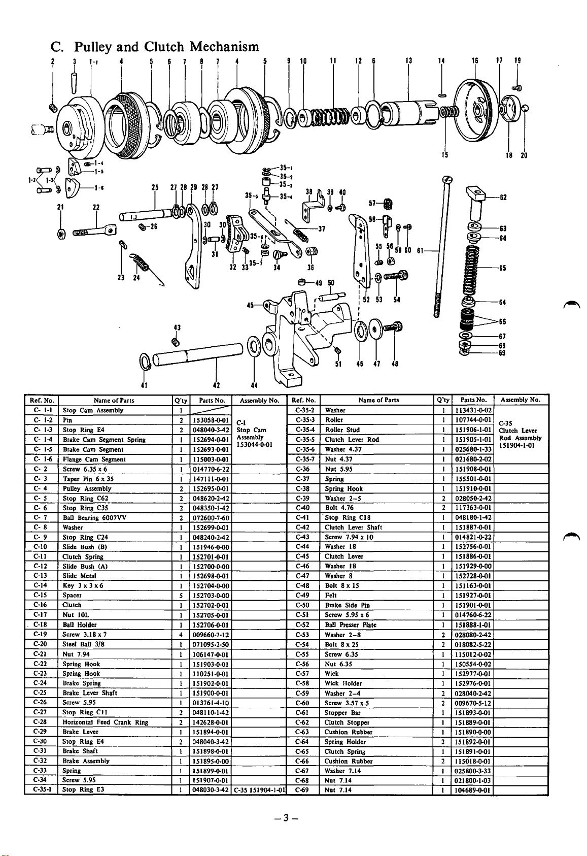
C.
From the library of: Superior Sewing Machine & Supply LLC
Pulley and Clutch Mechanism
l-·~{
~:~:
21
~
22
~0:0~21
25
I
r~
~~,~
41
Ref. No. Name
C-
1-1
Stop Cam Assembly
C-
1-2
Pin
Stop
Ring
C· 1·3
C-
1-4
Brake Cam Segment Spring
C-
1·5
Brake Cam Segment
C·
1-6
Flange Cam Segment
Screw 6.35 x 6
C·
2
Taper
3
C·
C-
4
Pulley Assembly
c-
5 Stop Ring C62
C-
6
Stop Ring C35
C-
7
Ball
C· 8 Washer
C-
9
Stop Ring C24
C-10
Slide
C-11
Clutch Spring
C-12 Slide Bush (A)
C-13
Slide
C-14
Key
C-15
Spacer
C-16
Clutch
C-17
Nut IOL
C-18
BaU
C-19
Screw
C-20
Steel
C-21
Nut 7.94
C-22
Spring
Spring
C·23
C-24
Brake Spring
C-25
Brake Lever Shaft
C-26
Screw
C-27
Stop
C-28
Horizontal Feed Crank Ring
C-29
Brake Lever
C-30
Stop
C-31
Brake Shaft
C-32
Brake Assembly
C-33 Spring
C-34
Screw
Stop
C-35·1
E4
Pin 6 x 35
Bearing 6007VV
Bush
(8)
Metal
3 x 3 x 6
Holder
3.18 x 7
Ball
3/8
Hook
Hook
5.95
Ring
Cll
Ring
E4
5.95
Ring
E3
of
Parts
Q'ty
I
2
2
1
I
1
I
I
2
2
2
2
1 1 s 2699-0-01
I 048240-2-42
1
1 152701-0-01
I
I I 5 2698-0-01
1
s
1 152702-o-01
1
I
4
1
1
1
1
1 1 51902-G-01
1 1 s I9oo-o-o 1
1
2
2
1
2
1
1
1 1 S 1899-o-O 1 C-67
I 151907-0-01 C-68
1
45
42
Parts No. Assembly No.
153058-0·01
----
048040-3-42 Stop Cam
152694-0-01
152693-0-01
115003-0-01
014770-6-22
147111-0-01
152695-Q-01 C-38
04862Q-2-42 C-39
048350-1-42
072600-7-60
151946-0-00
152700-Q-00
152704-o-oo
152703-Q-00
152705-0-01
152706-0-01
009660·7·12
071095-2-50
106147-0-01
151903-G-01
11
025 1·0·01
013761-4-10
048110.1-42
142628-0-01
151894-0-01
048040-3-42 C-64
1
5 1898-o-01
151895·0·00
048030.3-42
44
C-1
Assembly
153044-0-01
C-35
151904-1-01 C-69
Ref. No.
C-35-2
C-35-3
C-35-4
C-35-5
C-35-6
C-35-7
C-36
C-37
C-40
C-41
C-42
C-43
C-44
C-45
C-46
C-47
C-48
C-49
c-so
C-51
C-52
C-53
C-54
C-55
C-56
C·S7
C-58
C-59
C-60
C-61
C-62
C-63
C-65
C-66
57-fl
5Bln
la~
,,.,
Washer
Roller
Roller
Clutch
Washer 4.37
Nut 4.37
Nut
Spring
Spring
Washer
Bolt 4.76
Stop Ring
Clutch Lever Shaft
Screw
Washer
Clutch Lever
Washer 18
Washer 8
Bolt 8
Felt
Brake
Screw 5.95 x 6
Ball
Washer
Bolt 8 X
Screw 6.35
Nut 6.3S
Wick
Wick
Washer
Screw 3.57 x S
Stopper Bar
Clutch Stopper
Cushion
Spring Holder
Clutch
Cushion Rubber
Washer 7.14
Nut 7.14
Nut 7.14
Name
Stud
Lever Rod
5.95
Hook
2-5
CIS
7.94 x 10
18
xIS
Side
Pin
Presser Plate
2-8
25
Holder
2-4
Rubber
Sprin~
56
55
53 54
of
Parts
59
60
61
~62
~63
®------&4
Q'ty
Parts No.
113431-Q-02
I
107744-0-01
I
151906-1-01
I
1
151905-1-01
I
02568G-1·33
021680.2-02
I
1
151908-0-01
155501-0-01
1
151910-0-01
1
028050-2-42
2
117363-0-01
2
048180-1-42
I
151887-0-01
1
014821-0-22
1
I
152756-0-01
151886-0-01
1
151929-0-00
I
152728-0-01
1
I
151163·0·01
1
1S1927-0·0l
1
151901-0-01
014760-6-22
1
1
151888-1-01
028080.2-42
2
2
0 18082·5·22
115012-0-02
1
I
150554-0-02
1
152977-0·01
1 52976-Q-01
1
02804G-2-42
2
00967G-S-12
2
151893-0-01
1
151889-Q-01
1
1 s 1890-0-00
1
2
I 5 1892-o-O 1
1
15
1891-o-01
2
IIS018-0-01
025800-3-33
1
1
021800-1-03
1
104689-0-01
65
Assembly No.
C-35
Clutch
Lever
Rod Assembly
151904-1-01
-3-
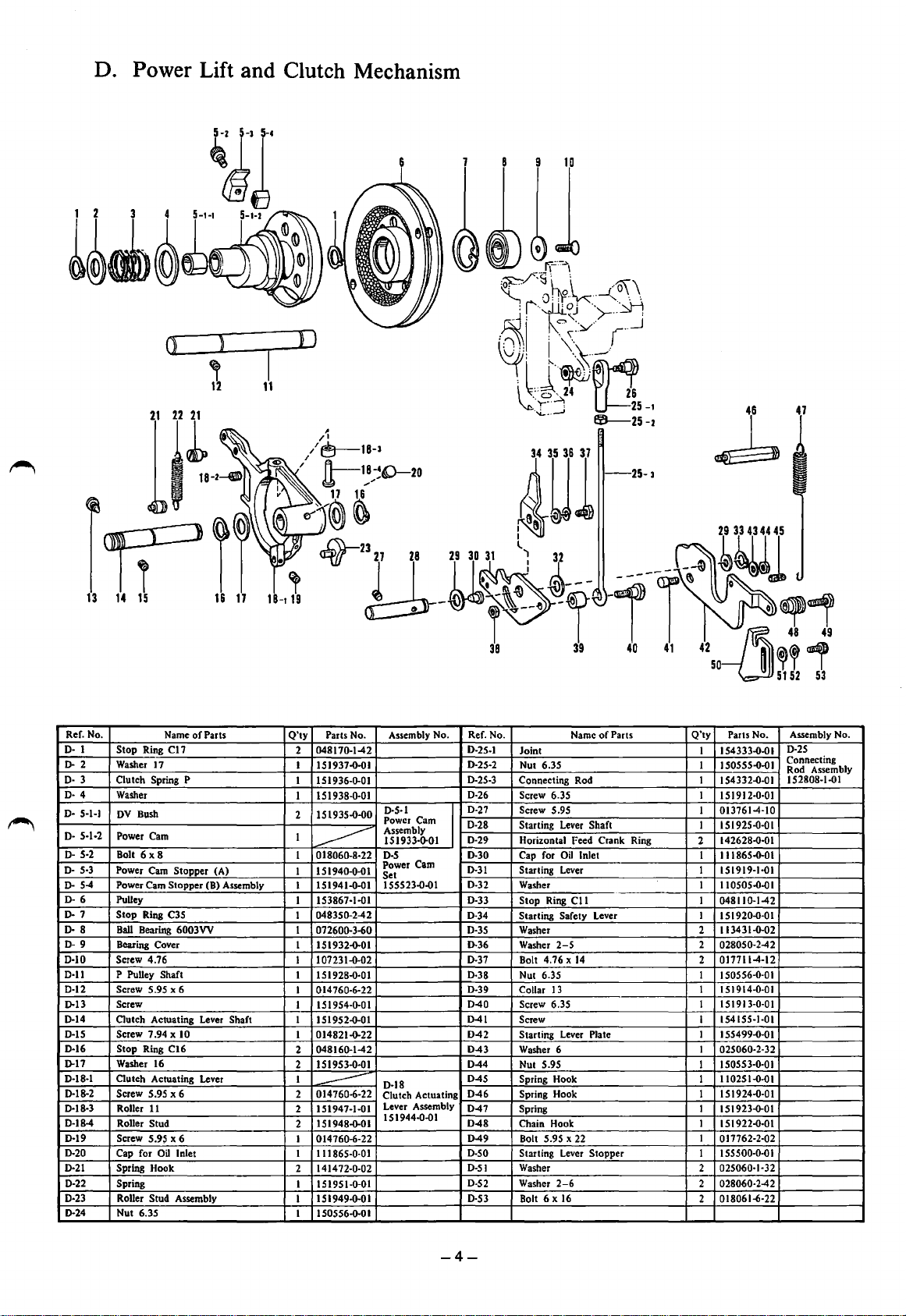
D. Power Lift and Clutch Mechanism
From the library of: Superior Sewing Machine & Supply LLC
0
I
11
ll~-·~
47
25-3
r~ri
13
14
15
16
17
1
B-t
19
'
Ref. No.
D·
I Stop Ring
D-2
D· 3 Clutch Spring P
D·
D·
D· 5·1·2 Power Cam
D· 5·2 Bolt
D· 5·3 Power Cam Stopper (A)
DD·
D·
D· 8
D0·10
0·11
D-12
D-13
D-14
D·lS
D-16 Stop
D-17 Washer 16
0·18·1
D-18-2
0·18-3
D-184
0·19
D-20
0·21
D-22
D·23
D-24
Washer
Washer
4
5-1-1
DV
Power Cam Stopper (B) Assembly
54
Pulley
6
Stop Ring C35
7
Ball
9
Bearing Cover
Screw 4.76
P
Screw 5.95 x 6
Screw
Clutch Actuating Lever
Screw
Clutch Actuating Lever
Screw
Roller
Roller Stud
Screw 5.95 x 6
Cap for
Spring
Spring
RoUer Stud
Nut 6.35
Name
Cl7
17
Bush
6x8
Bearing 6003VV
Pulley Shaft
7.94 x 10
Ring C16
5.95 x 6
11
Oil
Inlet
Hook
Assembly
of
Parts
Shaft
Q'ty
Parts No.
048170-142
2
I 151937-0-01
I 151936-0-01
1 151938-0-01
2 151935-0-00
1
1 018060-8·22
-------
1 151940-0-0 I
1
151941-0-01
153867-1-01
1
048350-242
1
1 072600-3-60
1
151932-0-01
07231-0-02
1 1
I 151928-0-01
014760-6-22
1
1 151954-0-01
1
151952-0-01
I 014821-0-22
048160-142
2
151953-0-01
2
1
.....------
014760-6-22
2
2 151947-1-01
151948-0-01
2
014760-6-22
1
I
111865·0-01
72-0-02
2 1414
I 151951-0-01
151949-0-01
1
I
150556-0-01
Assembly No. Ref. No.
0·5·1
Power Cam
Assembly
151933-0-01
D-5
Cam
Power
Set
155523-0-01
D-18
Clutch Actuating
Lever Assembly
151944-0-01
I
D-25-1
D-25-2
D-25-3
D-26
D-27
D-28
D-29
D-30
D-31
D-32
D-33
D-34
D-35
D-36
D-37
D-38
D-39
D-40
041
D-42
D-43
D-44
D-45
D-46
D-47
D-48
D-49
D-SO
D-51
D-52
D-53
Name
of
Parts
Joint I I
Nut 6.35 1 150555-0-01
Connecting Rod I
Screw
6.35 1 151912-0-01
5.95 1
Screw
Starting Lever Shaft
Horizontal Feed Crank Ring
Cap for
Oil
Starting Lever 1 151919-1-01
Washer
Stop Ring
Starting Safety Lever
Washer 2
Washer
Bolt 4.76 X
Nut 6.35 1 I 50556-0-01
Collar
Screw
Screw
Starting Lever Plate
Washer 6
Nut 5.95 1
Spring
Spring
Spring 1
Chain Hook I
Bolt
Starting
Washer 2
Washer
Bolt 6 x
Inlet 1 111865-0-01
Cll
2-5
14
13
6.35 1
Hook 1
Hook
5.95 x 22
Lever
Stopper I I 55500-0-0 I
2-6
16
Q'ty
Parts No.
54333-0-01
154332-0-01
0137614-10
1 151925-0-01
142628-0-01
2
1
110505-0-0 I
I
048110-142
1
151920-0-01
113431-0-02
2
028050-242
0177114-12
2
1 151914-0-01
151913-0-01
I 1541SS·I·Ol
I
155499-0-01
I 025060-2·32
150553-0-01
110251-0-01
1
1 s 1924-0·0 1
151923-0-01
151922·0·0 I
I
017762-2-02
025060·1·32
2
028060-242
018061-6·22
2
Assembly No.
D-25
Connecting
Rod Assembly
152808-1-01
-4-
 Loading...