How it Works
Log In / Sign Up
0
My Files
0
My Downloads
186009
History
Account Settings
Log Out
Buy Points
How it Works
FAQ
Contact Us
Questions and Suggestions
Users
show menu
Brother
Loading...
F
FA-V92A
FAX 1170
FAX 1270e
FAX 275
FAX 2820
FAX 333 mc
FAX 355MC
FAX 4750e
FAX 580MC
FAX 650 M
FAX 810MC
FAX-1000CL
FAX-1020E
FAX-1030Plus
FAX-1100CL
FAX-1150
FAX-1560
FAX-1835C
FAX-1840C
FAX-1860C
FAX-218
FAX-236
FAX-236S
FAX-2800J
FAX-2810
FAX-2825R
FAX-2920R
FAX-335MC
FAX-335MCS
FAX-4100e
FAX-418
FAX-515
FAX-525-MC
FAX-645
FAX-675
FAX-720CL
FAX-727
FAX-730CL
FAX-790CL
FAX-827
FAX-878
FAX-910CL
FAX-925
FAX-940
FAX-T86
2
FAX-T94
2
FAX2840ZU1
FAX315
FAX3800
FAX4750
FAX560
FAX8200P
Fax875MC
FB-N110
FB-V41A
FB1757T
2
FD3-B256
FD4-B271
2
FD4-B272
FD6-B941
FS-20
FS-40
FS-40WT
FS100WT
2
FS101
FS130QC
FS155
FS180QC
FS20s
FS210
2
FS40s
FS50
2
FS60
G
G20
GL-200
GL-H100
GLL200
GS2500
GS2700
GT-3
GT-341
GT-381
GT-782
GX-6000
GX-6500
GX-6750
GX-7000
GX-8500
GX37
GX9000
H
H1-H4
H105
H107
H200
H300
Hanami 17
Hanami 37s
HC-240
HC1850
HE 800B
Loading...
Loading...
Nothing found
FAX560
User Manual
83 pgs
1.48 Mb
0
User Manual
1 pgs
185.55 Kb
0
Service Manual
150 pgs
129.98 Mb
0
Service Manual
162 pgs
4 Mb
0
Service Manual
194 pgs
7.62 Mb
0
Table of contents
Loading...
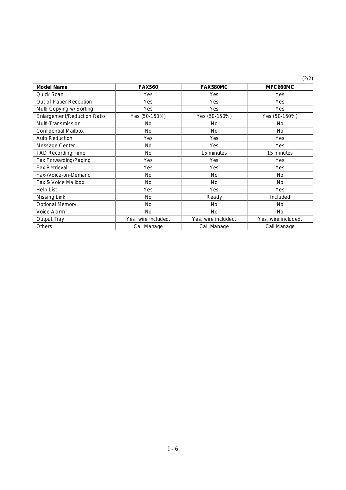
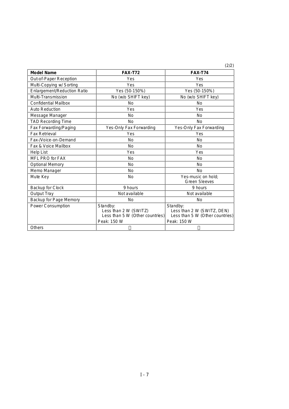
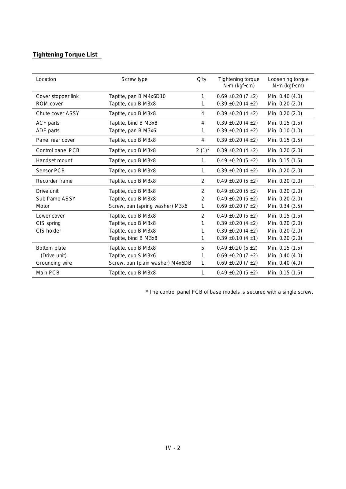
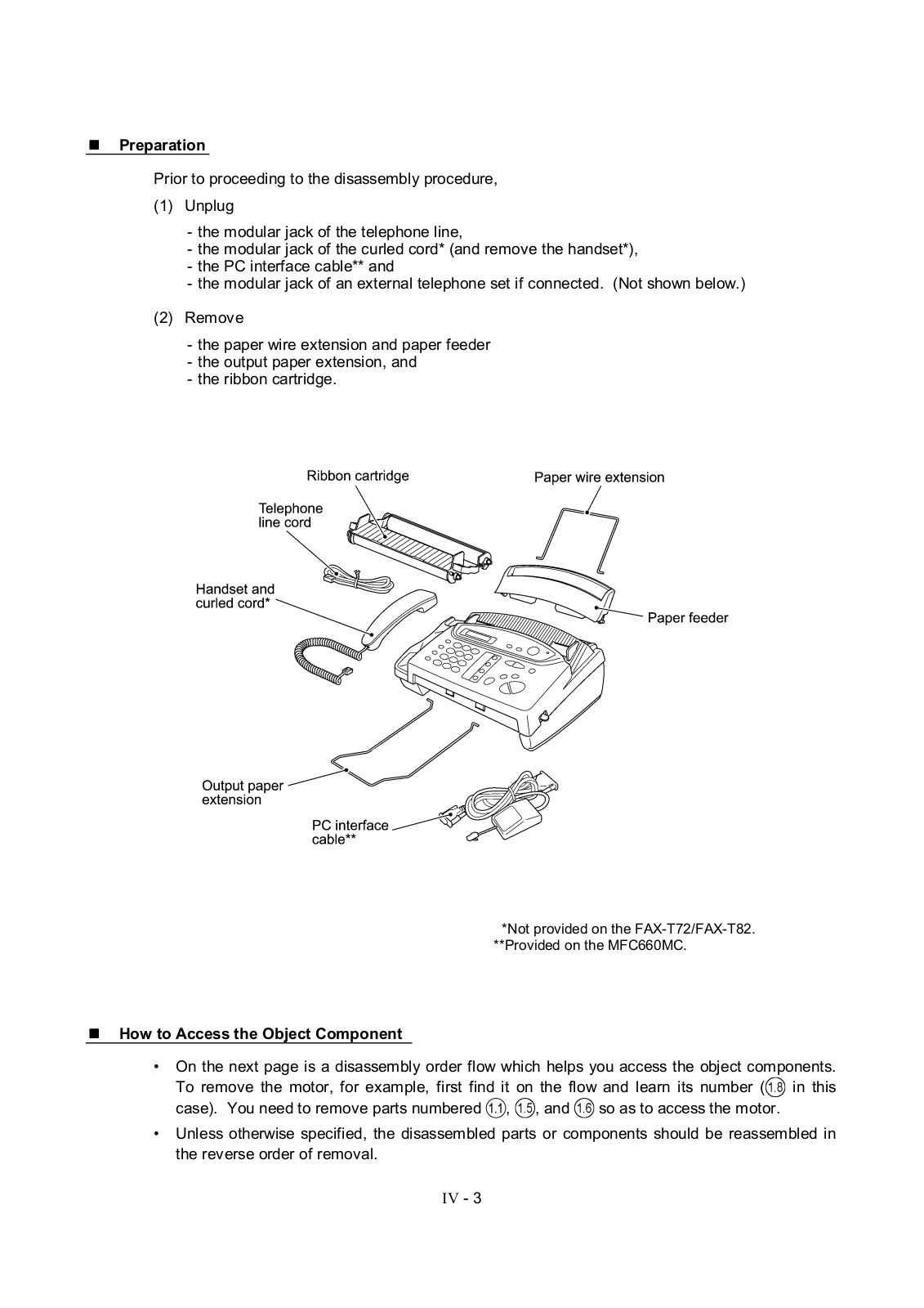
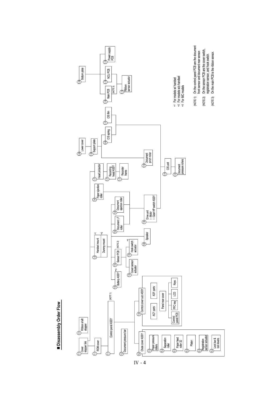
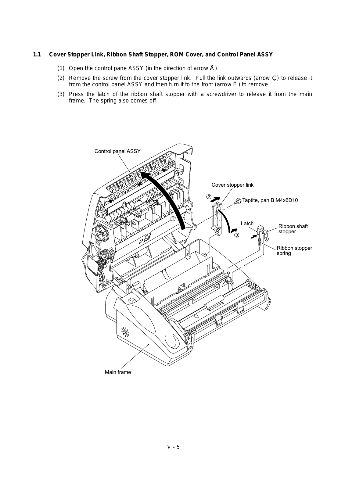
Brother FAX560, FAX580MC, MFC660MC, FAXT72, FAXT74 Service Manual
...
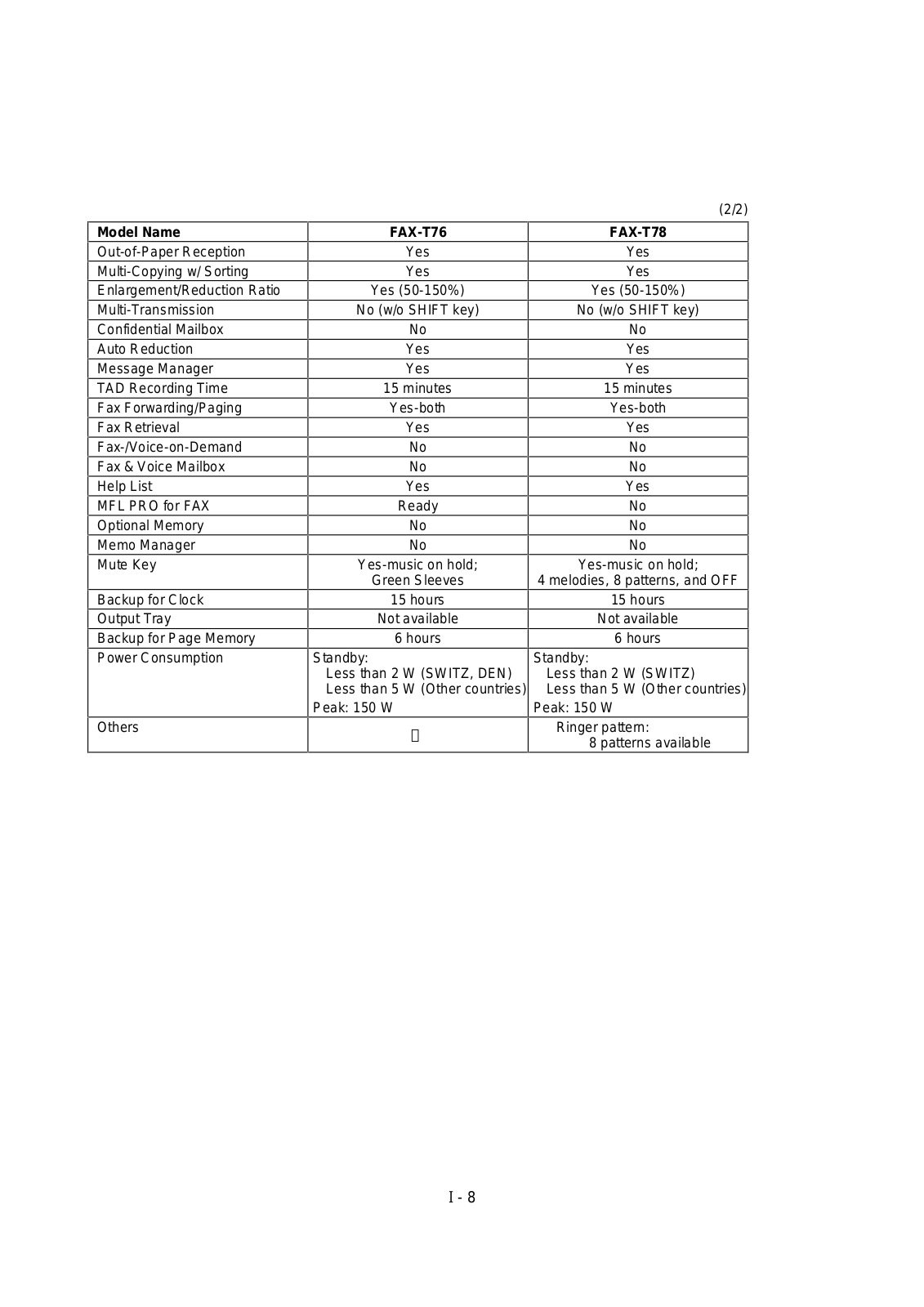
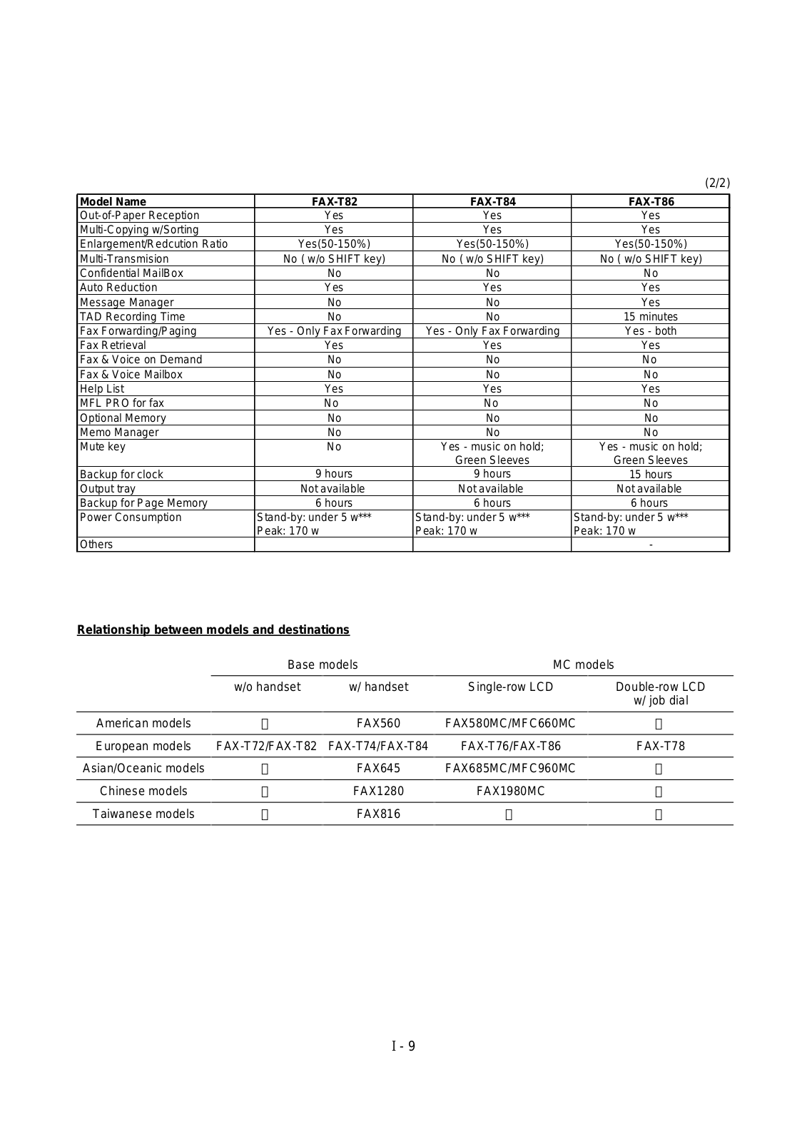
Brother FAX560, FAX580MC, MFC660MC, FAXT72, FAXT74, FAXT76, FAXT78, FAXT82, FAXT84, FAXT86, FAX645, FAX685MC, MFC960MC, FAX1280, FAX1980MC, FAX816 Service Manual
Download
0
(
0
)
Loading...
+
164
hidden pages
Unhide
You need points to download manuals.
1 point = 1 manual.
You can buy points or you can get point for every manual you upload.
Buy points
Upload your manuals
 Loading...