


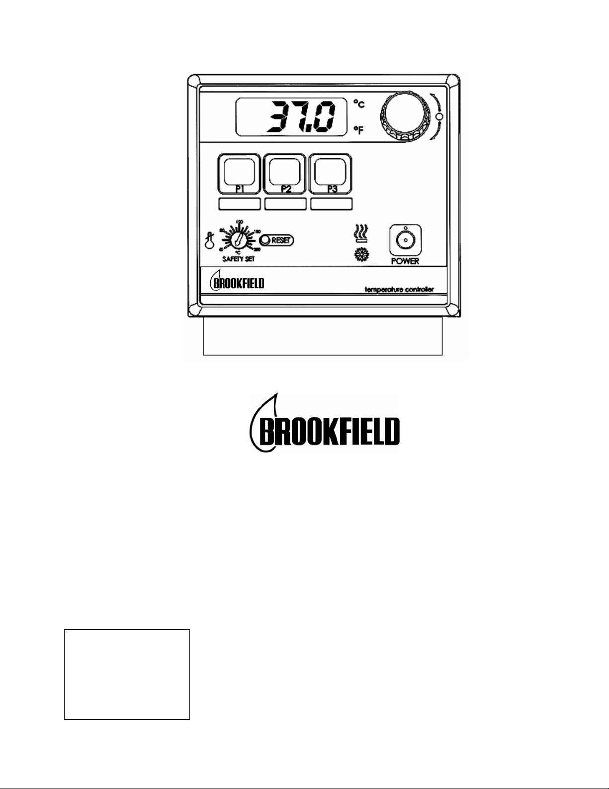
TC-602
Operators Manual
Circulating Bath with Digital Controller
110-241 Rev. D
ECN 1970
7/04

Table of Contents
Section 1 - General Information
1.1 Unpacking
1.2 Contents
1.3 General Description
1.4 Circulator Pump
1.5 Pump Inlet and Outlet Connections
1.6 Closed Loop Circulation
1.7 Reservoir Purge
1.8 Ambient and Cooling Coil
Section 2 - Standard Controller Information
2.1 Front and Rear Panels
2.2 Heater/Pump Assembly
Section 3 - Operation
3.1 Circulator Location
3.2 Filling the Reservoir
3.3 Power
3.4 Setting the Safety Set Point
3.5 Selecting Temperature Units
3.6 Setting the High Limit
3.7 Setting the Set Point Temperature
3.8 User-Defined Preset Temperatures
3.9 Local Lockout Feature
3.10 Stick-on Strips for Preset Buttons
3.11 Auto-Refrigeration Operation
3.12 Controller Display Messages
Section 4 - Calibration and Maintenance
4.1 Calibration
4.2 Heater
4.3 Pump Motor
4.4 Cleaning
4.5 Maintaining Clear Bath Water
4.6 Condenser, Air Vents, and Reusable Filter
(Refrigerating/Heating Circulators Only)
Section 5 - Troubleshooting
5.1 Unit Will Not Operate (no heat, cooling, or pumping)
5.2 No Pumping
5.3 Slow or Insufficient Pumping
5.4 No Heating
5.5 Insufficient Heating
5.6 No Cooling or Insufficient Cooling
5.7 Triac Failure
Section 6 - Reservoir Fluids
Section 7 - Service and Technical Support
7.1 Replacement Parts
Section 8 - After-sale Support
Section 9 – Warranty
Section 10 – EC Declaration of Conformity
1
This symbol marks chapters and sections of this instruction manual which are particularly relevant to safety. When
attached to the unit, this symbol draws attention to the relevant section of the instruction manual.
This symbol indicates that hazardous voltages may be present.
Read all instructions pertaining to safety, set-up, and operation.
Proper operation is the users’ responsibility.
Section 1 - General Information
1.1 Unpacking
Your circulator is shipped in a special carton.
unit is completely assembled and working properly. Set up and run the unit immediately to confirm
proper operation. Beyond one week, your unit may be warranty repaired, but not replaced. If the
unit is damaged or does not operate properly, contact the transportation company, file a damage
claim and immediately contact the company where your unit was purchased.
Remove any loose packing material that may have fallen into the reservoir during shipping. Before
powering up, check that nothing remains around the heater or circulator pump.
The instructions in this manual pertain to circulating baths, both refrigerated and cooling coil types.
Read the section pertaining to the special instructions for your model.
Retain the carton and all packing materials until the
1.2 Contents
Circulator Bath TC-102D TC-202D TC-502D TC-602D
Operators Manual, warranty card
3/16 in., 1/4 in., and 3/8 in. Nylon
Barbed Tubing Adapters
6 ft. of 1/4 in. ID Latex Tubing HT-Tubing
Adapter Fittings* 1/4 in. NPT – M16, Male (qty 2)
Beaker Platform(s) for Bath
Reservoir
Deck Lid(s)
Blue Hole Plugs
Note: Do NOT Use Above 120°C
Stick-on Strips for Preset Buttons (qty 2)
IEC Power Cord (qty 1)
Note: Work area "opening" is designed to measure samples directly in the bath. If additional viscometer height
is required (spindle/guard clearance), either a 4 inch rod extension (part number BLM-4E) used with type A lab
stand or an 18 inch rod replacement (part number VS-38) used with type S lab stand are available from
Brookfield or an authorized dealer.
*Included with 50Hz Models only.
— 600 ml
— 1000ml
— Solid
— w/Beaker Holes
— 3-1/2 inch
— 4-1/4 inch
701-402
510-209
510-211
TBPS300-295
110-241
510-011
701-402 (qty 2)
701-403
510-210
TBPS300-295
(qty 2)
TBPS300-296
701-402
510-290
510-293
TBPS300-295
701-402
510-246
2
1.3 General Description
Refrigerating/Heating and Heat Only Circulating Baths with the Digital Controller are designed for
use as stand-alone baths or to provide precise temperature control of fluids for closed loop
circulation to external equipment.
All Circulating Bath models feature a reservoir which may be used for immersing samples while the
unit is connected to an external device. Circulating bath models are equipped with either 6 or 10 liter
reservoirs. All wetted parts are corrosion resistant 300 series stainless steel.
Refrigeration is normally required for operation at temperatures below 40°C. However, refrigeration
should not be used when the fluid temperature is above 55°C. Refrigeration should not be turned on
when the ambient air temperature is above 32°C.
Model Specifications TC-102D TC-202D TC-502D TC-602D
Temperature Range Ambient +5° to 150°C Ambient +5° to 150°C -20° to 150°C -20° to 150°C
Temperature Stability
Readout Accuracy
Heater 1100 Watts for 115V models, 1600 Watts for 240V models
Reservoir Volumes 6 liters 10 liters 6 liters 6 liters
Pump Speeds 2-speed - 9 liters per minute or 15 liters per minute
Over-Temp Protection Yes, user-adjustable
Dimensions
l x w x h
Unit Weights 22 lbs (10.0 kg) 28 lbs (12.7 kg) 63 lbs (28.6 kg) 62 lbs (28 kg)
Power Requirement 60Hz 9A @ 115V / 1 / 60Hz
Power Requirement 50Hz 4.5A @ 240V / 1 / 50Hz
14¾ x 8¼ x 14 in.
37.5 x 13.3 x 35.6 cm
(105V - 125V)
(200V - 260V)
13¼ x 14¼x 13¼ in.
33.7 x 36.2 x 33.7 cm
9A @ 115V / 1 / 60Hz
(105V - 125V)
4.5A @ 240V / 1 / 50Hz
(200V - 260V)
± 0.05°C
± 0.5°C
15¾ x 18¾ x 17 in.
40 x 47.6 x 43.2 cm
10A @ 115V / 1 / 60Hz
(105V - 125V)
5A @ 240V / 1 / 50Hz
(200V - 260V)
15¾ x 8¼ x 22½ in.
40 x 21 x 57.1
10A @ 115V / 1 / 60Hz
(105V - 125V)
5A @ 240V / 1 / 50Hz
(200V - 260V)
Environmental Conditions:
● Indoor Use Only ● Over Voltage: Category ll
● Maximum Altitude: 2000 meters ● Operating Ambient: 5° to 30°C
● Relative Humidity: 80% for temperatures to 30°C ● Pollution Degree: 2
● Class 1: Residential, Commercial, Light Industrial ● Class 2: Heavy Industrial
1.4 Circulator Pump
The two-speed simplex (pressure) pump may be used for tempering of samples in the reservoir or
for circulation in closed loops. It is not designed for pumping from the circulator's reservoir into and
out of a second open reservoir.
The HIGH or LOW Speed Selection Switch on the rear of the Controller is used to select pump
speed. LOW is adequate for most applications and provides quieter pumping. HIGH is
recommended where temperature varies frequently and there is a need for fast recovery or when
pumping to multiple external units.
Speed Maximum Pump Outlet Ratings
Selection Line Frequency = 50/60Hz
HIGH 15 LPM / 2.6 PSI
LOW 9 LPM / 1.5 PSI
The data in the table above are based on the following criteria:
1. Maximum pump outlet flow rate is measured in liters per minute (LPM) with no restriction on the
pump outlet.
2. Maximum pump outlet pressure is measured in pounds per square inch (PSI) at no flow.
3. Water was used as the circulation fluid. Water has a viscosity of one centistoke. High viscosity
or low-density fluids will change these figures.
3
1.5 Pump Inlet and Outlet Connections
A
The pump inlet and outlet ports are female ¼ inch NPT connections that permit use of barbed tubing
adapters or hard plumbing fittings. ½ inch (13mm) ID tubing may also be slid over these connections
and held in place with a hose clamp. If the pump inlet and outlet are not used for external circulation,
they should be connected using the tubing provided with the unit in order to optimize fluid mixing
within the reservoir.
Picture 1: Inlet to Outlet Connection. When bath is not circulating with an external
device, the tubing provided with the unit should be used as shown above.
The nylon barbed tubing adapter fittings supplied with the unit are intended for temperature control from
-40°C to 93°C. For controlling temperature above 93°C, brass, stainless steel, or Teflon
recommended. ¼ inch NPT to M16 stainless steel male adapter fittings are provided with all 50Hz
models.
IT IS THE USER’S RESPONSIBILITY TO ENSURE THAT THE TUBING AND FITTINGS
CONNECTED TO THE CIRCULATOR ARE COMPATIBLE WITH THE BATH FLUID AND
TEMPERATURE RANGE BEING USED.
NOTE: The use of quick-connect fittings will restrict flow rate. Therefore a high or maximum pump
speed should be used.
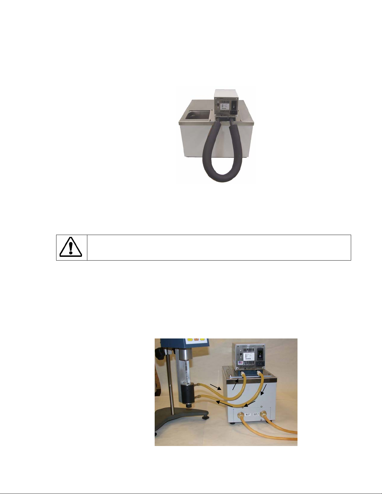
1.6 Closed Loop Circulation
Connect the pump inlet and outlet to the external apparatus (See Picture 2 below). To maintain
adequate flow, avoid restrictions in the tubing. When connecting the Circulator to more than two
closed loops, the use of a manifold made of "Y" adapters to divide the fluid into multiple banks is
recommended. After setting up multiple closed loops, check for adequate flow at the return manifold
of each loop and check that the bath fluid is at an adequate level. A booster pump may be added to
closed loops without damaging the Circulator’s bath pump.
®
fittings are
BATH INLET
B
TH OUTLET
Picture 2: Flow connections. Small Sample Adapter (shown),
DIN and UL Adapters, or Cone and Plate Viscometers.
4

The temperature control stability of a closed loop system is better at the external apparatus than in
the Circulator reservoir (provided the control point of the apparatus represents a constant load and is
well insulated). For example, if you circulate fluid through a viscometer at 50°C, the temperature
variation observed in the Circulator reservoir may be ±0.2°C while the temperature variation in the
viscometer may be only ±0.1°C.
Although temperature stability is generally better at the external apparatus control point, depending on
the length of tubing used and the efficiency of the insulation, the actual temperature reading at the
external apparatus may be slightly different than the temperature reading at the Circulator reservoir.
1.7 Reservoir Purge
When operating at low temperatures, atmospheric moisture tends to migrate into the reservoir and
condense. The 1/8 inch OD Reservoir Purge tube allows you to inject inert gas into the Circulating
bath to prevent the build-up of condensation.
1.8 Ambient and Cooling Coil (Non-refrigerated Models)
Used when auxiliary cooling of circulator coil is needed. Use of cooling coil is recommended when
the bath is operated at 24
o
– 35o C temperatures. When connected to a water source, the stainless
steel coil permits more rapid cooling from high temperatures and will ensure more precise
temperature control and faster response when operating close to ambient temperatures. The cooling
coil inlet and outlet ports are located on the rear of the bath, near the bottom of the reservoir.
5
 Loading...