


DV-I Viscometer
Table of contents
 Loading...
Brookfield Engineering Laboratories, Inc. Page 1 Manual No. M/92-021-O604
BROOKFIELD DIGITAL VISCOMETER
MODEL DV-I+
Operating Instructions
Manual No. M/92-021-O604
Please record the Model and Serial Number of your viscometer.
Having this information readily available will help us to assist you
should there be any questions regarding your instrument.
Model No.
Serial No.
SPECIALISTS IN THE
MEASUREMENT AND
CONTROL OF VISCOSITY
T
EL
800-628-8139 or 508-946-6200 F
AX
508-946-6262
www.brookfieldengineering.com
BROOKFIELD ENGINEERING LABORATORIES, INC.
11 Commerce Boulevard, Middleboro, MA 02346-1031 USA

Brookfield Engineering Laboratories, Inc. Page 2 Manual No. M/92-021-O604
TABLE OF CONTENTS
I. INTRODUCTION ....................................................................................... 3
I.1 Components ..................................................................................................................... 4
I.2 Utilities ............................................................................................................................ 4
I.3 Specifications .................................................................................................................. 5
I.4 Set-Up.............................................................................................................................. 5
I.5 Safety Symbols and Precautions ..................................................................................... 6
I.6 Key Functions.................................................................................................................. 7
I.7 Cleaning........................................................................................................................... 8
II.GETTING STARTED ................................................................................. 9
II.1 Auto Zero......................................................................................................................... 9
II.2 Spindle Selection ........................................................................................................... 10
II.3 Speed Selection & Setting ............................................................................................. 12
II.4 Autorange ...................................................................................................................... 13
II.5 CGS or SI Units Selection ............................................................................................. 13
II.6 Temperature Display in °F or °C Selection ................................................................... 14
II.7 Out of Range.................................................................................................................. 14
II.8 Operation ....................................................................................................................... 15
II.9 Timed Modes for Viscosity Measurement (available in instruments with V3.0 or greater).............................15
Appendix A - Cone/Plate Viscometer Set-Up.............................................................................. 20
Appendix B - Viscosity Ranges ................................................................................................... 24
Appendix C - Variables in Viscosity Measurement ..................................................................... 28
Appendix D - Spindle and Model Codes ..................................................................................... 30
Appendix E - Calibration Procedures .......................................................................................... 32
Appendix F - Special Speed Sets................................................................................................. 39
Appendix G- Communications.................................................................................................... 40
Appendix H - Laboratory Stand with Parts Identification ........................................................... 41
Appendix I - DVE-50 Probe Clip ............................................................................................... 43
Appendix J - Fault Diagnosis and Troubleshooting.................................................................... 44
Appendix K - Warranty Repair and Service................................................................................. 46
Appendix L - Viscosity T est Report............................................................................................. 49

Brookfield Engineering Laboratories, Inc. Page 3 Manual No. M/92-021-O604
I. INTRODUCTION
The Brookfield DV-I+ Viscometer measures fluid viscosity at given shear rates. Viscosity is a
measure of a fluid’ s resistance to flow . You will find a detailed description of the mathematics of
viscosity in the Brookfield publication “More Solutions to Sticky Problems” a copy of which
was included with your DV-I+.
The principle of operation of the DV-I+ is to drive a spindle (which is immersed in the test fluid)
through a calibrated spring. The viscous drag of the fluid against the spindle is measured by the
spring deflection. Spring deflection is measured with a rotary transducer. The measurement
range of a DV-I+ (in centipoise or milliPascal seconds) is determined by the rotational speed of
the spindle, the size and shape of the spindle, the container the spindle is rotating in, and the full
scale torque of the calibrated spring.
There are four basic spring torque series offered by Brookfield:
Spring Torque
Model dyne-cm milli Newton-m
LVDV-I+ 673.7 0.0673
RVDV-I+ 7,187.0 0.7187
HADV-I+ 14,374.0 1.4374
HBDV-I+ 57,496.0 5.7496
The higher the torque calibration, the higher the measurement range. The viscosity measurement
range for each torque calibration may be found in Appendix B.
All units of measurement are displayed according to either the CGS system or the SI sys-
tem.
1. Viscosity appears in units of centipoise (shown as “cP”) or milliPascal-seconds (shown as
mPa•s) on the DV-I+ Viscometer display.
2. Torque appears in units of dyne-centimeters or Newton-meters (shown as percent “%”) in
both cases) on the DV-I+ Viscometer display.
The equivalent units of measurement in the SI system are calculated using the following conver-
sions:
SI CGS
Viscosity: 1 mPa•s = 1 cP
Torque: 1 Newton-m = 10
7
dyne-cm
References to viscosity throughout this manual are done in CGS units. The DV-I+ Viscometer
provides equivalent information in SI units.

Brookfield Engineering Laboratories, Inc. Page 4 Manual No. M/92-021-O604
I.1 Components
Component Part Number Quantity
DV-I+ Viscometer varies 1
Model S Laboratory Stand Model S 1
Spindle Set with Case varies 1
LVDV-I+ set of four spindles or (SSL) 1
RVDV-I+ set of six spindles (#2 through #7) (SSR) 1
HA/HBDV-I+ set of six spindles (#2 through #7) (SSH) 1
For cone/plate versions, a spindle wrench, one cone spindle and sample cup,
Part No. CPE-44Y replace the spindle set.
Shipping Cap B-30-2 1
Power Cord DVP-65 1
Guardleg
(not supplied with HA/HB or Cone/Plate versions)
LVDV-I+ B-20Y 1
RVDV-I+ B-21Y 1
Carrying Case DVE-7Y 1
The following applies to DV-I+ Viscometers with the temperature probe option.
Look for this symbol throughout this manual for instructions pertaining
specifically to DV-I+ Viscometers with temperature probe option.
RTD Temperature Probe DVP-94Y 1
Probe Clip DVE-50A 1
Please check to be sure that you have received all components and that
there is no damage. If you are missing any parts, please notify Brookfield
Engineering or your local Brookfield agent immediately. Any shipping
damage must be reported to the carrier.
Tp
I.2 Utilities
Input Voltage: 115 VAC or 230 VAC
Input Frequency: 50/60 Hz
Power Consumption: 22 WATTS
Power Cord Color Code:
United States Outside United States
Hot (live) Black Brown
Neutral White Blue
Ground (earth) Green Green/Yellow

Brookfield Engineering Laboratories, Inc. Page 5 Manual No. M/92-021-O604
I.3 Specifications
Speeds: LVDV-I+: 0.0, 0.3, 0.6, 1.5, 3, 6, 12, 30, 60, 0.0,
(rpm) 0.5, 1, 2, 2.5, 4, 5, 10, 20, 50, 100
RV/HA/HBDV-I+: 0.0, 0.5, 1, 2, 2.5, 4, 5, 10, 20, 50, 100,
0.0, 0.3, 0.6, 1.5, 3, 6, 12, 30, 60
Weight: Gross Weight 20 lb 9 kg
Net Weight 17 lb 7.7 kg
Carton Volume 1.65 cu ft 0.05 m
3
Tp
Temperature Sensing Range: -100°C to +300°C (-148°F to +572°F)
Operating Environment: 0°C to 40°C Temperature Range (32°F to 104°F)
20% - 80% R.H.: non-condensing atmosphere
Analog Torque Output: 0 - 1 Volt DC (0 - 100% Torque)
Tp
Analog Temperature Output: 0-4 Volt DC (10 mV/°C)
Viscosity Accuracy: ±1% Full Scale Range in Use (See Appendix E for details)
Viscosity Repeatability: 0.2% of Full Scale Range in Use
Tp
Temperature Accuracy: ±1°C: -100°C to +149°C
±2°C: +150°C to +300°C
Electrical Certifications:
Conforms to CE Standards for: Electromagnetic Compatibility (EMC), Low Voltage
(LVD) and Safety Requirements for electrical equipment for measurement control and
laboratory use.
Certified to the applicable CSA and ANSI/UL Standards, for use in Canada and the
United States.
Installation Category II, Pollution Degree 2, Altitude 2000m (max).
I.4 Set-Up
1) To assemble the Model S Laboratory Stand, place the upright rod into the base (refer
to assembly instructions in Appendix H). The rack gear and clamp assembly should
face the front of the base. The upright rod is held in place with a screw which is
attached from the bottom of the base. Tighten this screw with a screwdriver.
2) Insert the mounting rod on the back of the DV-I+ Viscometer into the hole on the
clamp assembly. Be sure that the clamp screw, VS-41Y, is loose.
3) Tighten the VS-41Y clamp screw. Adjust the Viscometer to be as close to level as
possible while tightening the clamp screw.

Brookfield Engineering Laboratories, Inc. Page 6 Manual No. M/92-021-O604
Tp
4) Connect the optional RTD temperature probe to the temperature port
on the
rear panel of the DV-I+, if provided.
5) The Viscometer must be level. The level is adjusted using the two Leveling Screws
(VS-3) on the base. Adjust so that the bubble level on top of the DV-I+ is centered
within the circle. Check level periodically during use.
6) Make sure that the AC power switch at the rear of the DV-I+ is in the OFF position.
Connect the power cord to the socket on the back panel of the instrument and plug it
into the appropriate AC line.
The AC input voltage and frequency must be within the appropriate range as shown
on the name plate of the viscometer. The DV-I+ must be earth grounded to ensure
against electronic failure!
7) For Cone/Plate models, refer to Appendix A.
I.5 Safety Symbols and Precautions
Safety Symbols
The following explains safety symbols which may be found in this operating manual.
Indicates hazardous voltages may be present.
Refer to the manual for specific warning or caution information to avoid personal injury
or damage to the instrument.
Precautions
If this instrument is used in a manner not specified by the manufacturer, the protection
provided by the instrument may be impaired.
This instrument is not intended for use in a potentially hazardous environment.
In case of emergency, turn off the instrument and then disconnect the electrical cord from
the wall outlet.
The user should ensure that the substances placed under test do not release poisonous,
toxic or flammable gases at the temperatures to which they are subjected to during the
testing.
Brookfield Engineering Laboratories, Inc. Page 7 Manual No. M/92-021-O604
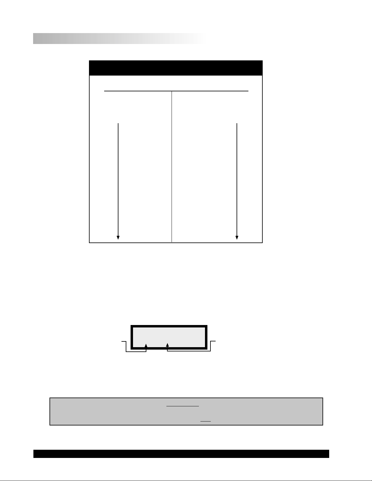
SET
SPEED
SELECT
SPINDLE
SELECT
SPINDLE
MOTOR
ON/OFF
AUTO
RANGE
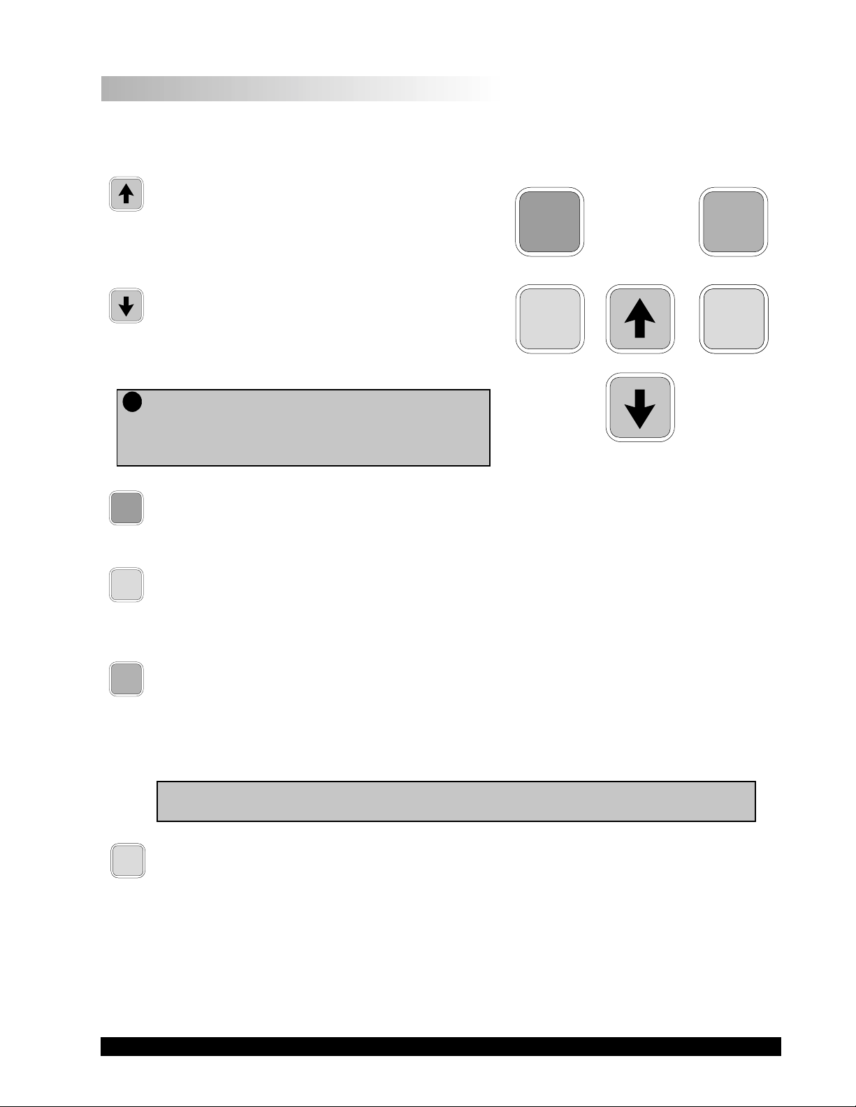
Figure I-1
I.6 Key Functions
Figure I-1 shows the control keys on the face of the DV-I+ Viscometer. The following describes each
key's function.
UP ARROW
This key is used to scroll UP (in an increasing
value direction) through the available speed or
spindle tables.
DOWN ARROW
This key is used to scroll DOWN (in a decreasing
value direction) through the available speed or
spindle tables.
Tp
Note: Pressing and holding the DOWN ARROW key
during the POWER ON will enable the
temperature display to be read in °C or °F.
See Section II.1.
MOTOR
ON/OFF
MOTOR ON/OFF
Turns the motor ON or OFF.
SET
SPEED
SET SPEED
Causes the DV-I+ to begin running at the currently selected speed. Used for Time to Torque
and Timed Stop tests. (See Section II.9 - Timed Modes for Viscosity Measurement.)
AUTO
RANGE
AUTO RANGE
Presents the maximum (100% torque) viscosity attainable (known as full scale range) for the
spindle speed selected. This feature is functional when the motor is running. Viscometer
allowable error is 1% of the maximum (100% torque) viscosity value; minimum recommended
viscosity range is 10% of the maximum viscosity value.
Note: Pressing and holding the AUTO RANGE key during power on will enable the
viscosity display to be changed between CGS and SI units (see Section II.5).
SELECT
SPINDLE
SELECT
SPINDLE
SELECT SPINDLE
Initiates spindle selection on the first press and then selects the currently scrolled-to spindle
when pressed a second time. Used for Time to Torque and Timed Stop tests. (See Section
II.9 - Timed Modes for Viscosity Measurement.)

Brookfield Engineering Laboratories, Inc. Page 8 Manual No. M/92-021-O604
I.7 Cleaning
Be sure to remove spindle from instrument prior to cleaning. Severe instrument
damage may result if cleaned in place.
Instrument and Keypad: Clean with dry, non-abrasive cloth. Do not use solvents
or cleaners.
Immersed Components (spindles): Spindles are made of stainless steel. Clean with non-abra-
sive cloth and solvent appropriate for sample material that
is not aggressive to immersed components.
When cleaning, do not apply excessive force which may result in bending spindles.
Brookfield Engineering Laboratories, Inc. Page 9 Manual No. M/92-021-O604
II. GETTING STARTED
II.1 Auto Zero
Before readings may be taken, the Viscometer must be Autozeroed. This action is performed
each time the power switch is turned on. The display window on the Viscometer will guide you
through the procedure as follows:
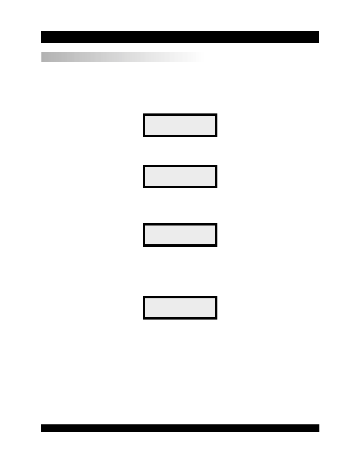
Turn the power switch (located on the rear panel) to the ON position. This will result in the
following screen display:
BROOKFIELD DV-I+
RV VISCOMETER
Figure II-1
After a few seconds, the following screen appears:
BROOKFIELD DV-I+
VERSION 5.1
Figure II-2
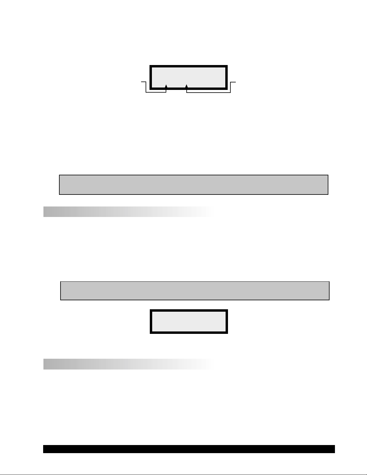
No key press is required at this point. After a short time, the display will clear and the following
will be displayed:
REMOVE SPINDLE
PRESS ANY KEY
Figure II-3
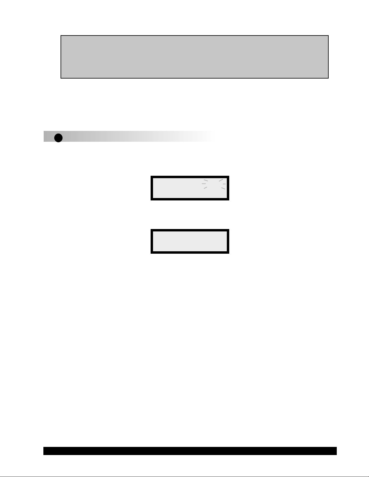
After removing the spindle and pressing any key , the DV-I+ begins its Autozero. The screen will
flash “Autozeroing”. Note: Be sure that the viscometer is level before initiating Autozero.
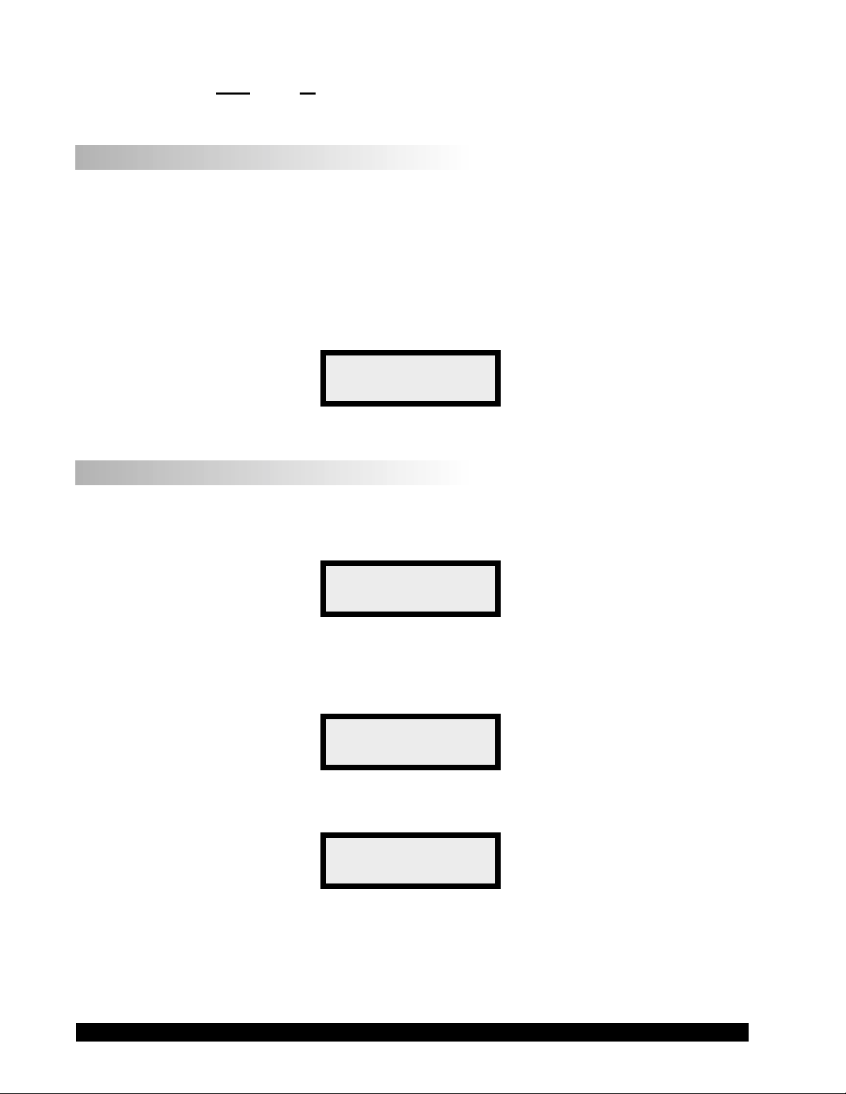
After approximately 15 seconds, the flashing stops and the following screen appears:
REPLACE SPINDLE
PRESS ANY KEY
Figure II-4
Pressing any key at this point results in the display of the DV-I+ default screen:
Brookfield Engineering Laboratories, Inc. Page 10 Manual No. M/92-021-O604
cP 123E3 70.1°F
0.0RPM % 0.0
cP 0.0 S01
0.0RPM % 0.0
(with Temperature Probe)
(without Temperature Probe)
Calculated Viscosity (cP or m•Pas)
Speed
Temperature (if available)
% T orque
Spindle Selected
Figure II-5
The display will vary slightly depending upon the status of the last spindle entry.
NOTE: If the viscosity value exceeds 99,999, scientific notation is used. In FigureII-5, the
viscosity value is 123,000 cP.
II.2 Spindle Selection
LVDV-I+ V iscometers are provided with a set of four spindles and a narrow guardleg; RVDV-I+
Viscometers come with a set of six spindles and a wider guardleg; HADV-I+ and HBDV-I+
V iscometers come with a set of six spindles and no guardleg. (See Appendix E for more informa-
tion on the guardleg.)
The spindles are attached to the viscometer by screwing them on to the lower shaft. Note that the
spindles have a left-hand thread. The lower shaft should be held in one hand and lifted up. The
spindles should be screwed to the left. The face of the spindle nut and the matching surface on the
lower shaft should be smooth and clean to prevent eccentric rotation of the spindle. Spindles can
be identified by the number on the side of the spindle nut.
The DV-I+ requires a Spindle Entry Code number to calculate viscosity values. The two digit
entry code for each spindle may be found in Appendix D.
NOTE: The DV-I+ will remember the Spindle Entry Code which was in use when power
was turned off.
II.2.1 Spindle Selection for Models WITHOUT Temperature Display
Pressing the SELECT SPINDLE key will cause the characters on the top line of the display to
begin to blink . It will blink for about three seconds. If the UP or DOWN ARROW keys are pressed
(while
SS
SS
S is blinking) the two character spindle value to the right of the
SS
SS
S character will begin to
change (in either an increasing or decreasing direction depending upon which ARROW key is
pressed) for each press of the key. If the ARROW key is pressed and held, the display will scroll
through the spindle codes for as long as the ARROW key is depressed. When it reaches the last
item in the list (either at the top or bottom of the list) the spindle code displayed will “roll-over”
to either the first or last spindle code and the scroll action will continue.
When the desired spindle code is displayed, release the ARROW key to halt further scrolling.
Press the SELECT SPINDLE key once again. This will cause the
SS
SS
S character to cease blinking and
the new spindle code will be accepted for use in viscometer calculations.
Brookfield Engineering Laboratories, Inc. Page 11 Manual No. M/92-021-O604
NOTE: You have approximately three seconds in which to press the SELECT SPINDLE
key before the blinking stops. If you fail to press the SELECT SPINDLE key
before the blinking stops you will have to repeat the above steps and re-select the
desired spindle.
The DV-I+ will begin to calculate using the new spindle parameters as soon as the SELECT
SPINDLE key is pressed the second time.
Tp
II.2.2 Spindle Section for Models WITH Temperature Display
The steps for selecting and accepting a spindle entry are the same as Section II.2.1 except that
when
SELECT SPINDLE is depressed, the temperature display is temporarily replaced by the spindle
entry code until the entry code is accepted (Figure II-6):
cP 123.4 SP31
10 RPM % 89.7
Figure II-6
Once the spindle entry code is accepted, the screen will return to the default display:
cP 0.0 70.1°F
0.0RPM % 0.0
Figure II-7
The DV-I+ may also be programmed at Brookfield Engineering for “special” user spindles.
These “special” spindles will show up on the spindle scroll list starting with the designation "AA"
and continuing through "AZ". Contact Brookfield Engineering regarding your needs for special
spindles.
Brookfield Engineering Laboratories, Inc. Page 12 Manual No. M/92-021-O604
II.3 Speed Selection & Setting
Table II-1 shows the available speed selections.
DV-I+ SPEEDS SETS
LV RV/HA/HB
0.0 0.0
0.3 0.5
0.6 1.0
1.5 2.0
3.0 2.5
6.0 4.0
12.0 5.0
30.0 10.0
60.0 20.0
0.0 50.0
0.5 100.0
1.0 0.0
2.0 0.3
2.5 0.6
4.0 1.5
5.0 3.0
10.0 6.0
20.0 12.0
50.0 30.0
100.0 60.0
Beginning
When scrolling
“UP”
Beginning
When scrolling
“UP”
Table II-1
The DV-I+ may also be programmed with “special” speed sets. A list of special speed sets is
included in Appendix F. Please consult Brookfield Engineering or your local dealer/distributor
for any special speed requirements not addressed by the standard or special speed sets.
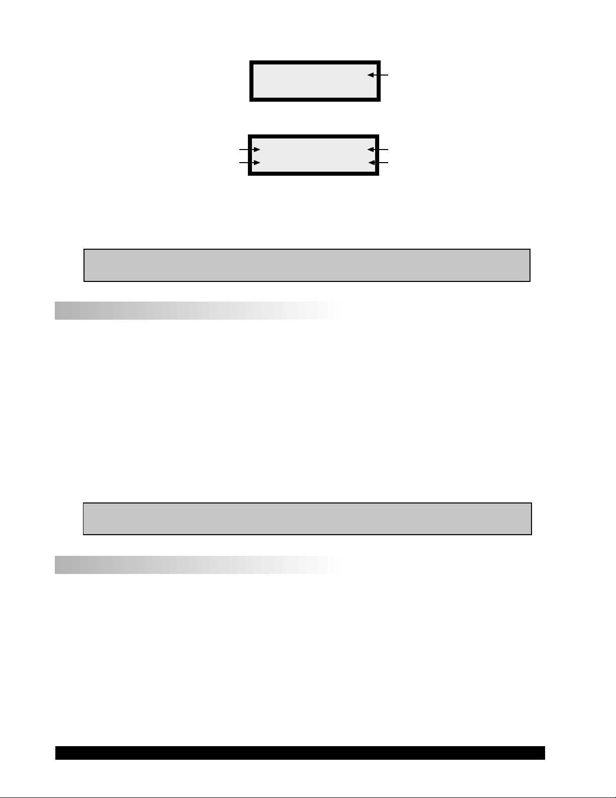
To select a viscometer speed first press either the UP or DOWN ARROW keys which will cause the
area to the right of RPM (on the bottom line) to display the currently selected speed. Figure II-
8 shows the DV-I+ had been operating at 10 RPM, and the current selected speed is 10 RPM.
cP 872.0 S01
10RPM10 % 87.2
Flashing “Selectable” Speed
Operating Speed
Figure II-8
If the ARROW key is pressed just once and then released, the characters
RPMRPM
RPMRPM
RPM will blink for three
seconds, then will cease blinking resulting in no change to the speed entry.
NOTE: The speed selection process remembers the last value of scrolled-to speed so that
the next time you initiate a speed change (by pressing an ARROW key), the DV-
I+ will begin its scroll display from the last entered value.
The last-scrolled-to speed does not necessarily have to be the same as the speed at which the
Brookfield Engineering Laboratories, Inc. Page 13 Manual No. M/92-021-O604
DV-I+ is currently running. The user may operate at a given speed and pre-set the DV-I+ to the
next desired speed before that speed will be used. For example, if the DV-I+ is currently running
at 10 RPM and was previously scrolled to 20 RPM, a single press of either ARROW key would
result in the Figure II-9 screen display:
cP 872.0 S01
10RPM20 % 87.2
Operating Speed Scrolled to Selected Speed
Figure II-9
Pressing the SET SPEED key would cause the DV-I+ to begin running at 20 RPM.
Pressing the MOTOR ON/OFF again immediately starts the DV-I+ running at the last scrolled-to-
speed. If you had been running at 10 RPM, pressed
MOTOR ON/OFF and then re-started the DV-
I+ by pressing
MOTOR ON/OFF once again, you would again be running at 10 RPM. However , if
while the motor was off you had scrolled to a new speed of 20 RPM, pressing the MOTOR ON/OFF
key would start the DV-I+ running at 20 RPM.
NOTE: During both spindle or speed selection and scrolling operations, the DV-I+ will
continue to calculate and display viscosity (cP) and torque (%).
II.4 Autorange
The AUTO RANGE key allows you to determine the maximum calculated viscosity (full scale
reading) possible with the current spindle/speed setting. Pressing the key at any time will cause
the current viscosity display to change and show that maximum viscosity. The screen torque
display will now display a flashing “%100.0” to indicate this special condition. This maximum
viscosity and flashing %100.0 value will be displayed for as long as the AUTO RANGE key is
depressed. Figure II-10 shows the AUTO RANGE function for the situation where the No. 1 RV
spindle is rotating at 10 RPM. The full scale range is 1000 cP (or 1000 mPa
.
s).
NOTE: If the motor is off or the RPM is 0.0, the maximum viscosity displayed will be 0.0
cP (or 0.0 mPa
.
s).
cP 1000 S01
10RPM %100.0
Figure II-10
II.5 CGS or SI Units Selection
Pressing and holding the AUTO RANGE key during power on will enable the viscosity display to
be read in either CGS or SI units. To change the unit format:
1. Turn the power off.
2. Press and hold the AUTO RANGE key and turn the power ON.
The DV-I+ will retain the unit selection when the viscometer is turned OFF.
Brookfield Engineering Laboratories, Inc. Page 14 Manual No. M/92-021-O604
CGS SI
Viscosity cP mPa
.
s
II.6 Temperature Display in °F or °C Selection
Pressing and holding the DOWN ARROW key during power on will enable the temperature display
to be read in either degrees Fahrenheit or degrees Centigrade. To change the units format:
1. Turn the power OFF.
2. Press and hold the DOWN ARROW key and turn power ON.
The DV-I+ will retain the unit selection when the viscometer is turned OFF.
The following screen depicts the changes to the default screen when displaying temperature in
the Fahrenheit scale and viscosity display in SI units:
mPas123.4 70.1°F
10 RPM % 89.7
Figure II-11
II.7 Out of Range
Brookfield recommends taking viscosity readings between 10% and 100% of scale. The DV-I+
gives indications for out of specification or out-of-range operation. When % (Torque) readings
exceed 100.0 % (over-range), the display changes to that shown in Figure II-12:
cP EEEE S01
10 RPM % EEEE
Figure II-12
You must change either speed or spindle to correct this condition. If you operate at spindle
speeds that produce % (T orque) below 10.0 % (under-range), the DV -I+ flashes both % (Torque)
and cP (Viscosity) on and off:
cP 78.0 S01
10RPM20 % 7.8
Figure II-13
Negative % (Torque) will be displayed as shown in Figure II-14:
cP ---- S01
10RPM20 % -0.2
Figure II-14
Viscosity values will be displayed as “- - - -” when the % (Torque) is below zero.

Brookfield Engineering Laboratories, Inc. Page 15 Manual No. M/92-021-O604
II.8 Operation
The following procedure is outlined for making a viscosity measurement in a 600 ml low form
Griffin beaker.
1. Mount the guardleg on the DV-I+ Viscometer (LV and RV series). Attach the spindle to
the lower shaft. Lift the shaft slightly, holding it firmly with one hand while screwing the
spindle on with the other (note left-hand thread). Avoid putting side thrust on the shaft.
2. Insert and center spindle in the test material until the fluid's level is at the immersion groove
in the spindle's shaft. With a disc-type spindle, it is sometimes necessary to tilt the spindle
slightly while immersing to avoid trapping air bubbles on its surface. (You may find it more
convenient to immerse the spindle in this fashion before attaching it to the Viscometer.)
3. To make a viscosity measurement, select the desired speed setting. Allow time for the
indicated reading to stabilize. The time required for stabilization will depend on the speed
at which the Viscometer is running and the characteristics of the sample fluid. For
maximum accuracy, readings below 10% should be avoided. Additional information on
making viscosity measurements is available in Appendix C or the Brookfield publication
“More Solutions to Sticky Problems”.
4. Press the
MOTOR ON/OFF key to turn the motor “OFF” when changing a spindle or
changing samples. Remove spindle before cleaning. Clean spindles after use.
5. Interpretation of results and the instrument's use with non-Newtonian and thixotropic
materials is discussed in the booklet, “More Solutions to Sticky Problems”, and in
Appendix C, Variables in Viscosity Measurements.
II.9 Timed Modes for Viscosity Measurement (available in instruments with V3.0 or greater)
The Timed Modes allow the viscometer user to implement Timed Stop and Time to Torque
capabilities with the DV-I+ V iscometer. This feature will allow the user to set up the viscometer
(i.e. select spindle and speed) and then record readings for a fixed period of time (Timed Stop) or
until a set torque value is attained (Time to Torque). A series of menus will ask the user to input
minutes and seconds (Timed Stop) or % torque (T ime to Torque) and will then begin timing when
the user presses the MOTOR ON/OFF key to ON. A message will be displayed showing time
remaining (or time elapsed) and the appropriate display item (viscosity or torque) will be updated
continuously during the event. Upon completion, the viscometer will display a screen stating that
the test is complete and will also display the final recorded value for the viscosity in the first case,
and the time in minutes and seconds to reach the torque limit in the second case. Pressing the UP
or DOWN arrow keys will allow alternate data to be examined and pressing any other key will
bring the user back to the default (normal) viscometer display with the motor OFF. If the user
wishes to run another test, repeat the above steps.
II.9.1 Set Up
1. The user must pre-select the display unit option: CGS or SI.
2. The user then selects (via the UP and DOWN arrows) the spindle speed.
NOTE: If 0.0 RPM is the selected speed setting (the default after executing AUTOZERO)
the timed modes can be executed; however, the results will be meaningless
showing no viscosity values.
Loading...