


 BROOKFIELD MODEL 106


Programmable Temperature Controller
Operating Instructions
Manual No. M/02-207-C0109
SPECIALISTS IN THE
MEASUREMENT AND
CONTROL OF VISCOSITY
with offices in: Boston • Chicago • London • Stuttgart • Guangzhou
BROOKFIELD ENGINEERING LABORATORIES, INC.
11 Commerce Boulevard, Middleboro, MA 02346 USA
TEL 508-946-6200 |
or 800-628-8139 (USA |
excluding MA) |
FAX 508-946-6262 |
INTERNET http://www.brookfieldengineering.com |
|
|
|
|
Brookfield Engineering Labs., Inc. |
Page |
Manual No. M/02-207-C0109 |
|
|
|

|
|
TABLE OF CONTENTS |
|
I. |
INTRODUCTION............................................................................................................................ |
3 |
|
II. |
SPECIFICATIONS......................................................................................................................... |
4 |
|
III. SAFETY SYMBOLS AND PRECAUTIONS....................................................................................... |
5 |
||
IV. INSTALLATION.............................................................................................................................. |
6 |
||
|
IV.1 |
Probe........................................................................................................................... |
6 |
|
IV.2 |
Recorder...................................................................................................................... |
6 |
|
IV.3 |
Comm Port.................................................................................................................. |
7 |
|
IV. 4 |
AC, Power Switch and Power Fuse............................................................................ |
7 |
|
IV. 5 |
Load............................................................................................................................ |
8 |
V. CONTROL KEYS AND DISPLAY PANEL....................................................................................... |
9 |
||
|
V.1 |
The °F/°C Key............................................................................................................ |
9 |
|
V.2 |
The Run/Stby Key.................................................................................................... |
10 |
|
V.3 |
The Set Key............................................................................................................... |
10 |
|
V.4 |
The Program Key...................................................................................................... |
10 |
|
V.5 |
The Arrow (direction) Keys...................................................................................... |
10 |
|
V.6 |
The Heat On LED..................................................................................................... |
10 |
|
V.7 |
The Remote LED...................................................................................................... |
11 |
|
V.8 |
The Run LED............................................................................................................ |
11 |
|
V.9 |
The Program LED..................................................................................................... |
11 |
|
V.10 |
Piezo Buzzer............................................................................................................. |
11 |
VI. PROGRAMMABLE TEMPERATURE CONTROLLER OPERATION................................................. |
12 |
||
|
VI.1 |
Powering Up the Temperature Controller................................................................. |
12 |
|
VI.2 |
Control Modes.......................................................................................................... |
12 |
|
VI.3 |
Single SetPoint Operation - Non Program Mode..................................................... |
12 |
|
VI.4 |
Program Mode.......................................................................................................... |
14 |
|
VI.5 |
Entering a Temperature/Time Program..................................................................... |
14 |
|
VI.6 |
Reviewing and Editing An Existing Program........................................................... |
17 |
|
VI.7 |
Running a Temperature/Time Program..................................................................... |
17 |
|
VI.8 |
Stopping A Program.................................................................................................. |
18 |
|
VI.9 |
Remote Operation..................................................................................................... |
18 |
VII. REMOTE OPERATION USING RHEOCALC©................................................................................ |
21 |
||
VIII. ERROR MESSAGES AND FAILSAFES......................................................................................... |
21 |
||
|
VIII.1 |
Open Sensor Error..................................................................................................... |
22 |
|
VIII.2 |
Thermosel Overheat Error........................................................................................ |
22 |
|
VIII.3 |
High/Low Temperature Limit Error.......................................................................... |
23 |
|
IX. TROUBLESHOOTING................................................................................................................. |
23 |
|
APPENDIX A - External Mode Command Protocol Demonstration................................................................. |
24 |
||
APPENDIX B - Warranty Repair and Service.............................................................................................................. |
27 |
||
Brookfield Engineering Labs., Inc. |
Page |
Manual No. M/02-207-C0109 |

I.INTRODUCTION
The Programmable Temperature Controller is used with the Brookfield Thermosel for measuring viscosity at high temperatures. The unit includes a solid state proportioning temperature controller, a means for entering the desired temperature/time data and appropriate status indicators.
The Programmable Temperature Controller can maintain a constant temperature in the Thermosel or be programmed to effect temperature changes. The program indicates each desired temperature and the period of time that the Thermosel should be maintained at that temperature. In this manual, a time/temperature combination is termed an “entry” or “step”. A program can have up to 10 entries. The Programmable Temperature Controller can automatically stop maintaining the temperature of the Thermosel Container at the termination of the program. Alternatively, the Programmable Temperature Controller can be programmed to maintain the final preset temperature at the termination of the program.
The front panel is used to display and edit temperature/time programs. The front panel also presents the status of the system (e.g. the current temperature of the Thermosel and error messages).
An RS-232C communication channel is provided to establish control and/or observe operating parameters via a remote device (e.g. a personal computer or a remote terminal). Rheocalc, an optional software package available from BROOKFIELD, can be used, in conjunction with the Brookfield DV-II+ Pro Viscometer, DV-III+ Rheometer or DV-III Ultra Rheometer, to provide temperature/time inputs to the Programmable Temperature Controller via a personal computer.
(Optional Cable HT-106 is required to interface the Programmable Temperature Controller to the
PC.)
An analog output port is available to send temperature data to a strip chart recorder. Optional
Recorder Output Cable (Part No. HT-88Y) is available from Brookfield.
A list of the parts shipped with the Programmable Temperature Controller is provided below. If any parts are missing or damaged, please contact BROOKFIELD or your local authorized representative immediately.
SYSTEM CONTENTS
Description |
Part Number |
Quantity |
|
|
|
Programmable Temperature Controller |
HT-110 |
1 |
RTD Temperature Probe |
DVP-94Y |
1 |
Operating Instructions Manual |
M/02-207 |
1 |
Table I.1
If you intend to use this Programmable Temperature Controller with a Brookfield DV-II+ Pro Viscometer, DV-III+ or DV-III Ultra Rheometer, optional cables are required:
•For direct temperature control (via DV-III+/DV-III Ultra), you will require optional cable
DVP-141
•For temperature control using Rheocalc software (via computer), you will require optional cable HT-106
Please contact Brookfield or your local authorized representative with your Thermosel Controller
Serial Number to obtain these cables.
Brookfield Engineering Labs., Inc. |
Page |
Manual No. M/02-207-C0109 |

II. |
|
SPECIFICATIONS |
|
|
|
|
|
||
|
Utilities |
|
|
|
|
|
|||
|
|
|
|
|
|
|
|
|
|
|
|
|
|
|
VOLTAGE SPECIFICATIONS |
|
|
||
|
|
|
|
|
|
|
|
|
|
|
|
|
|
Input Voltage |
|
85 to 265 VAC |
|
|
|
|
|
|
|
|
|
|
|
|
|
|
|
|
|
Input Frequency |
|
50/60 Hz |
|
|
|
|
|
|
|
|
|
|
|
|
|
|
|
|
|
Replaceable Fuses |
|
Two fuses, 2A, 250V, 5 x 20 mm, Fast Acting |
|
|
|
|
|
|
|
Load |
|
TRIAC (250 watts max) |
|
|
|
|
|
|
|
|
|
(Check the label beneath the Programmable |
|
|
|
|
|
|
|
|
|
Temperature Controller for the voltage require- |
|
|
|
|
|
|
|
|
|
ments of our unit) |
|
|
|
|
|
|
|
|
|
|
Table II.1 |
||
|
Controller |
|
|
|
|
|
|||
|
|
|
|
|
|
|
|||
|
|
|
|
MEASUREMENT/CONTROL SPECIFICATIONS |
|
||||
|
|
|
|
|
|
|
|
|
|
|
|
|
|
Range |
|
|
15°C above ambient to 300°C |
|
|
|
|
|
|
|
|
|
27°F above ambient to 572°F |
|
|
|
|
|
|
Resolution |
|
|
0.1 °C or °F |
|
|
|
|
|
|
Reading Accuracy |
|
|
±1.0°C (between ambient and +150°C) |
|
|
|
|
|
|
|
|
|
|
||
|
|
|
|
|
|
|
±2.0°C (between +151°C and +300°C) |
|
|
|
|
|
|
|
|
|
|
|
|
|
|
|
|
Setpoint Accuracy |
|
|
The temperature will be maintained within 0.3°C |
|
|
|
|
|
|
|
|
|
of the setpoint |
|
|
|
|
|
|
Recorder Output Voltage |
0 to 4 Volts |
|
|||
|
|
|
|
|
|
|
1 volt = 0°C/32°F; 4 Volts = 300°C/572°F |
|
|
|
|
|
|
|
|
|
Table II.2 |
||
|
|
|
|
|
|
|
|
|
|
|
|
NOTE: The temperature accuracies stated above are a result of the combined accuracies of |
|||||||
|
|
the Programmable Temperature Controller, the temperature probe, and the Thermo |
|||||||
|
|
container. |
|
|
|
|
|
||

 Thermo Container


|
THERMO CONTAINER SPECIFICATIONS |
|
|
|
|
Range |
|
15°C above ambient to 300°C |
|
|
|
Accuracy |
|
±0.5% of the controller setpoint |
|
|
Table II.3 |
Brookfield Engineering Labs., Inc. |
Page |
Manual No. M/02-207-C0109 |


 Electrical Certifications


Conforms to CE Standards:
BSEN 50081-1: Emission Standard - Light Industrial
BSEN 50082-1: Immunity Standard - Light Industrial
BSEN 61010-1: Safety requirements for electrical equipment, for measurement, control and laboratory use.
III.SAFETY SYMBOLS AND PRECAUTIONS
Safety Symbols
The following explains safety symbols which may be found in this operating manual.
Refer to the manual for specific warning or caution information to avoid personal injury or damage to the instrument.
Precautions
This instrument is not intended for use in a potentially hazardous environment.
If this instrument is not used in a manner specified by the manufacturer, the protection provided by the instrument may be insufficient.
Brookfield Engineering Labs., Inc. |
Page |
Manual No. M/02-207-C0109 |
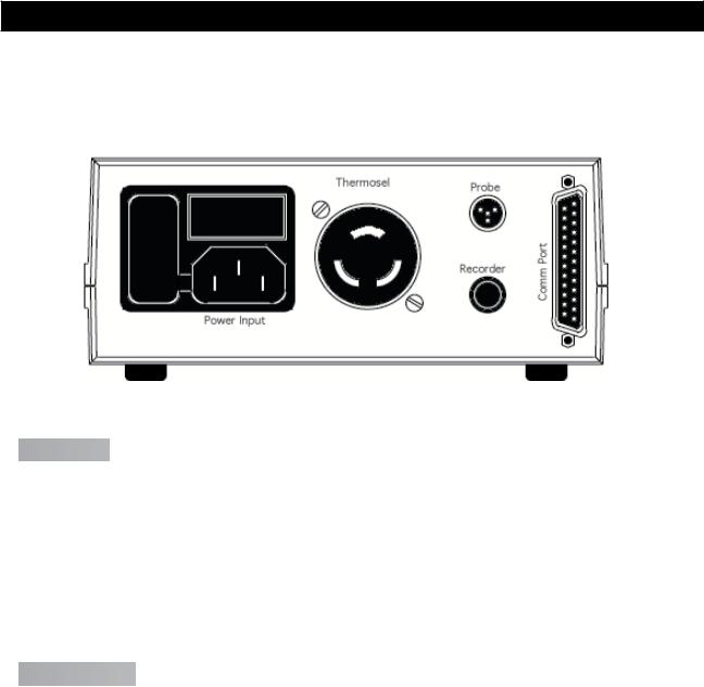
IV. INSTALLATION
Plug the temperature sensor into the Probe receptacle, the Thermo Container into the Thermosel receptacle, the strip chart recorder (if used) into the Recorder jack and a remote RS-232C device (again, if used) into the Comm Ports 25-pin plug. The rear panel will appear as follows in
Figure IV.1.
Figure IV.1

 IV.1 Probe


The probe is a 100 ohm precision platinum RTD (resistance temperature detector) probe (Brookfield Part Number DVP-94Y) which is plugged into the Probe port on the rear panel.
Note: The RTD Probe must be plugged into the Programmable Temperature Controller and the RTD Probe end must be inserted into the Thermo Container before power is turned on. The Controller will beep on/off. An error message (0.RTD) will be displayed if the Programmable Temperature Controller is turned on and the RTD Probe is not installed.

 IV.2 Recorder


The Recorder jack provides a signal to a recording device (the optional HT-88Y cable is provided for this service) such as a strip chart recorder. The full scale recorder output signal range is from 0 to 4 V for the Thermosel systems. The temperature can be obtained from the output potential (in mV) as follows:
The 0 to 4 volt output corresponds to a temperature range of -100°C (-148°F) to 300°C (572°F). Realistically, temperatures in Thermosel systems will typically be above ambient. Therefore, output voltages will generally range from slightly less than 2 volts (<100°C) to the full 4 volts (300°C). The temperature corresponding to any intermediate output voltage can be obtained from the following:
(0.1 * mV) -100 |
= |
°C (Centigrade Temperatures) |
(0.18 * mV) -148 |
= |
°F (Fahrenheit Temperatures) |
Brookfield Engineering Labs., Inc. |
Page |
Manual No. M/02-207-C0109 |

For example, the temperature corresponding to a reading of 2.5 V (2500 mV) would be calculated as follows:
(0.1 x 2500) - 100 = 150°C or (0.18 x 2500) - 148 = 302°F
The recorder jack is a standard 1/4” phono jack. An optional analog output cable (Brookfield Part No. HT-88Y) is available from Brookfield.

 IV.3 Comm Port


The COMMUNICATION PORT provides an RS-232C data link to an external device such as a computer or remote terminal. The RS-232C pin assignments are:
RS-232C PIN CONNECTIONS
Pin Number |
Function |
|
|
2 |
Data Out (Tx) |
3 |
Data In (Rx) |
7 |
Ground (Gnd) |
13 and 25 |
Remote Mode |
Table IV.1
NOTE: Pin number 13 should be connected to pin 25 on the connector being inserted into the Comm Port in order to place the Programmable Temperature Controller in the Remote mode (indicated by the lit REMOTE LED on the instrument front panel).
|
RS-232C Protocol |
|
|
|
|
Baud Rage |
|
9600 |
|
|
|
Data Bits |
|
8 |
Stop Bits |
|
1 |
Parity |
|
None |
|
Table |
IV.2 |

 IV.4 AC, Power Switch and Power Fuse


The primary power requirement for the Programmable Temperature Controller can range from 85 to 265 VAC; 50/60 Hz and must be connected through the power cord. The voltage for which the unit has been configured will be indicated on the bottom of the Programmable Temperature Controller. The power consumption at 120 VAC is 400 ma plus the Thermo Container load power.
The power fuse must be a 2A/250V Littlefuse, fast acting type, GMA series or equivalent. This fuse protects the controller electronics only.
Brookfield Engineering Labs., Inc. |
Page |
Manual No. M/02-207-C0109 |


 IV.5 Load


The Thermosel connector is provided to supply power to the Thermo Container. The connector is specially keyed so that other loads cannot be readily substituted. The power limit supplied by this connector is 300 watts.
NOTE: The current provided to the Thermosel connector is potentially dangerous. Do not insert or remove the Load plug while power is applied to the Programmable Temperature Controller.
Brookfield Engineering Labs., Inc. |
Page |
Manual No. M/02-207-C0109 |

V.CONTROL KEYS AND DISPLAY PANEL
The front panel of the unit, which includes all user controls and status indicators, is shown in
Figure V.1:
Figure V.1
The digital display is used to display system status, to set up temperature/time programs, to review temperature/time programs and to present certain messages to the user.
The allowable range for temperature entries is:
0.0°C to 300.0°C (32.0°F to 572.0°F), with a minimum increment of 0.1° (either scale). The allowable range for time entries is from 1 to 900 minutes with a minimum increment of 1 minute.
If a proposed temperature value is above the maximum input for that unit, or if a proposed temperature value is below the minimum input for that unit, an audible sound (beep) will be heard and the current maximum (or minimum) value will be displayed.
The various buttons and light emitting diodes (LED’s) have the following functions or meaning:

 V.1
V.1
 °C°F
°C°F  The °F/°C Key


This key is used to toggle the units in which temperatures are displayed and entered. The right most digit in the main display indicates the units currently being used (F = Fahrenheit; C = Centigrade).
Brookfield Engineering Labs., Inc. |
Page |
Manual No. M/02-207-C0109 |
 Loading...