


BROOKFIELD DV1
Digital Viscometer
Operating Instructions
Manual No. M14-023
SPECIALISTS IN THE
MEASUREMENT AND
CONTROL OF VISCOSITY
with offices in: Boston • Chicago • London • Stuttgart • Guangzhou
BROOKFIELD ENGINEERING LABORATORIES, INC.
11 Commerce Boulevard, Middleboro, MA 02346 USA
TEL 508-946-6200 or 800-628-8139 (USA e xcluding MA) FAX 508-946-6262 INTERNET http://www.brookfieldengineering.com

|
|
TABLE OF CONTENTS |
|
I. INTRODUCTION......................................................................................................... |
5 |
||
I.1 |
Components........................................................................................................................ |
6 |
|
I.2 |
Utilities |
................................................................................................................................ |
7 |
I.3 |
Components and Dimensions............................................................................................. |
8 |
|
I.4 |
Specifications.................................................................................................................... |
10 |
|
I.5 |
Installation......................................................................................................................... |
11 |
|
I.6 |
Safety Symbols .......................................................................................and Precautions |
11 |
|
I.7 |
Key Functions.................................................................................................................... |
12 |
|
I.8 |
Preventative ..........................................................................Maintenance and Cleaning |
13 |
|
II. GETTING STARTED................................................................................................... |
14 |
||
II.1 Power Up.......................................................................................................................... |
14 |
||
II.2 AutoZero........................................................................................................................... |
14 |
||
II.3 |
Navigation........................................................................................................................ |
15 |
|
II.4 Home Screen.................................................................................................................... |
15 |
||
II.5 |
Spindle ..............................................................................................................Selection |
15 |
|
II.6 Speed Selection................................................................................................................ |
18 |
||
II.7 |
Full Scale ................................................................................................................Range |
19 |
|
II.8 |
Options............................................................................................................................. |
20 |
|
|
II.8.1 .............................................................................................................. |
Run Until |
20 |
|
II.8.2 .............................................................................................................. |
Test View |
21 |
|
II.8.3 .............................................................................................................. |
Visc Units |
22 |
|
II.8.4 ........................................................................................................... |
Temp Units |
22 |
|
II.8.5 ........................................................................................................... |
Tmp. Offset |
23 |
|
II.8.6 .............................................................................................................. |
Language |
23 |
|
II.8.7 ................................................................................................................ |
Connect |
23 |
|
II.8.8 .................................................................................................................... |
Reset |
23 |
|
II.8.9 ................................................................................................................... |
About |
23 |
|
II.8.10 .................................................................................................................. |
Service |
24 |
II.9 |
Printing............................................................................................................................. |
24 |
|
III. Making Viscosity ............................................................................Measurements |
26 |
||
III.1 Quick Start....................................................................................................................... |
26 |
||
III.2 Preparation ..........................................................................for Making Measurements |
26 |
||
III.3 Selecting ...............................................................................................a Spindle/Speed |
27 |
||
III.4 Running .................................................................................................................a Test |
27 |
||
III.5 Communication .................................................................with Wingather SQ Software |
28 |
||
Appendix A - Cone/Plate Viscometer Set-Up............................................................... |
31 |
Appendix B - Viscosity Ranges..................................................................................... |
36 |
Appendix C - Variables in Viscosity Measurements..................................................... |
40 |
Appendix D - Spindle Entry Codes and SMC/SRC Values............................................. |
42 |
Appendix E - Spindle Entry Codes and Range Coefficients.......................................... |
45 |
Appendix F - Calibration Check Procedures................................................................. |
47 |
Appendix G - The Brookfield Guardleg........................................................................ |
54 |
Appendix H - Laboratory Stands with Parts Identification........................................... |
56 |
Appendix I - DVE-50A Probe Clip................................................................................. |
58 |
Appendix J - Fault Diagnosis and Troubleshooting...................................................... |
59 |
Appendix K - Online Help and Additional Resources................................................... |
59 |
Appendix L - Warranty Repair and Services................................................................. |
60 |
Viscosity Test Report.................................................................................... |
(tear out page) |

I.INTRODUCTION
The Brookfield DV1 Viscometer series has provided exceptional value for viscometer users since its introduction in 1981. Brookfield has continued to develop and improve the DV1 to maintain its position in the market as the best value for Q/C applications. The Brookfield DV1 Viscometer continues in this tradition of innovation, quality and value. The incorporation of a large graphical display and “Hot Keys” has allowed for a new and improved user interface that preserves single speed data collection methods (or multiple speeds when using Wingather SQ), which makes using the DV1 Viscometer easier than ever before.
The Brookfield DV1 Viscometer measures fluid viscosity which is a measure of a fluid’s resistance to flow. You will find a detailed description of the science of viscosity in the Brookfield publication “More Solutions to Sticky Problems”, a copy of which was included with your DV1.
The principle of operation of the DV1 is to drive a spindle (which is immersed in the test fluid) through a calibrated spring. The viscous drag of the fluid against the spindle is measured by the spring deflection. Spring deflection is measured with a rotary transducer. This system provides continuous sensing and display of the measurement during the entire test. The measurement range of a DV1 (in centipoise or milliPascal-seconds) is determined by the rotational speed of the spindle, the size and shape of the spindle, the container the spindle is rotating in, and the full-scale torque of the calibrated spring.
There are four basic spring torque series offered by Brookfield:
Model |
Spring Torque |
|
dyne•cm |
milli Newton•m |
|
DV1MLV |
673.7 |
0.0673 |
DV1MRV |
7,187.0 |
0.7187 |
DV1MHA |
14,374.0 |
1.4374 |
DV1MHB |
57,496.0 |
5.7496 |
The higher the torque calibration, the higher the measurement range. The viscosity measurement range for each torque calibration may be found in Appendix B.
The DV1 is configured to accept an optional temperature probe, which allows temperature readout over the range -100°C to +300°C (-148°F to + 572°F). This option allows ambient temperature measurement or temperature measurement of the sample during viscosity testing. Contact Brookfield or your local Brookfield dealer for more information on this instrument option.
All units of measurement are displayed according to either the CGS system or the SI system.
1.Viscosity appears in units of centipoise (shown as “cP”) or milliPascal-seconds (shown as mPa•s) on the DV1 Viscometer display.
2.Torque appears in units of dyne-centimeters or Newton-meters (shown as percent “%”)
in both cases) on the DV1 Viscometer display.
Tp3. Temperature appears in units of Celsius (shown as C) or Fahrenheit (shown as F) on the DV1 Viscometer display.
The following applies to DV1 Viscometers when using an optional temperature probe. Look for the
symbol Tpthroughout this manual for instructions pertaining specifically to DV1 Viscometers with temperature probe option.
Brookfield Engineering Laboratories, Inc. |
Page 5 |
Manual No. M14-023 |

The equivalent units of measurement in the SI system are calculated using the following conversions:
Viscosity: |
SI |
= |
CGS |
1 mPa•s |
1 cP |
||
Torque: |
1 Newton•m |
= |
107 dyne•cm |
References to viscosity throughout this manual are done in CGS units. The DV1 Viscometer provides equivalent information in SI units.
I.1 Components
COMPONENT
DV1
Model G Laboratory Stand
Spindle Set with Case*
DV1MLV set of four spindles (#61 through #64) DV1MRV set of six spindles (#02 through #07) DV1MHA/HB set of six spindles (#02 through #07)
Shipping Cap*
Power Cord (115V/230V)
Guardleg* ( not supplied with HA/HB versions) DV1MLV
DV1MRV Carrying Case Operating Manual
For cone/plate versions:
Spindle wrench Cone spindle Sample cup
Standard
With embedded temperature probe and cable
PART NUMBER |
QUANTITY |
varies |
1 |
Model G |
1 |
varies |
1 |
SSL or SSLK† |
|
SSR or SSRK† |
|
SSH or SSHK† |
|
B-30-3Y |
1 |
DVP-65/66 |
1 |
varies |
1 |
B-20Y or B20KY† |
|
B-21Y or B21KY† |
|
DVE-106 |
1 |
M14-023 |
1 |
CP-23 |
1 |
CPA-XXZ |
1 |
varies |
1 |
CPA-44YZ |
|
CPA-44PYZ |
|
The following applies to DV1 Viscometers with the temperature probe option. Look for the symbol
Tpthroughout this manual for instructions pertaining specifically to DV1 Viscometers with temperature probe option.
OPTIONAL ITEMS |
DVP-94Y |
1 |
RTD Temperature Probe |
||
Probe Clip |
DVE-50A |
1 |
RTD Cable when supplied with Cone/Plate version |
SC4-61Y |
1 |
Please check to be sure that you have received all components and that there is no damage. If you are missing any parts, please notify Brookfield Engineering or your local Brookfield agent immediately. Any shipping damage must be reported to the carrier.
*Not supplied with Cone/Plate version.
†“K” in the part number identifies EZ-Lock spindles.
Brookfield Engineering Laboratories, Inc. |
Page 6 |
Manual No. M14-023 |

I.2 Utilities
Input Voltage: |
115 VAC or 230 VAC |
Input Frequency: |
50/60 Hz |
Power Consumption: |
50 VA |
Power Cord Color Code: |
|
|
|
Hot (live) |
United States |
|
Outside United States |
Black |
|
Brown |
|
Neutral |
White |
|
Blue |
Ground (earth) |
Green |
|
Green/Yellow |
Brookfield Engineering Laboratories, Inc. |
Page 7 |
Manual No. M14-023 |

I.3 Components and Dimensions
DV1 Viscometer
Model G Laboratory Stand
Spindle Set 
Shipping
Cap
LV Guard
Leg
Cone/Plate Option |
Temperature Probe Option |
• For use with SSA or C/P:
Wrench 
Temperature Cable 


 SC4-61Y
• For use in beaker:
Cone Spindle |
Sample Cup |
Figure I-1


 Temperature Probe Clip
 Temperature Probe
Brookfield Engineering Laboratories, Inc. |
Page 8 |
Manual No. M14-023 |
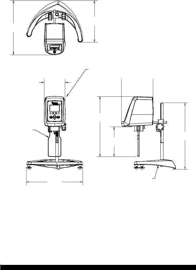
13 13/32 [34.1 cm]
5 3/16 [13.2 cm]
B-21Y
RV GUARD LEG
ASSEMBLY
3 3/16 [8.1 cm] 

13 7/8 [35.2 cm]
Brookfield Engineering Laboratories, Inc.
10 5/16 [26.2 cm]
DV1 VISCOMETER
7 51/64  [19.8 cm]
14 7/8 [37.8 cm]
7 3/8 [18.7 cm]
GV-1201 LAB STAND BASE ASSEMBLY
Figure I-2
Page 9
16 13/32 [41.7 cm]
Manual No. M14-023

I.4 Specifications
Speeds: |
0.0, 0.3, 0.6, 1.5, 3, 6, 12, 30, 60, |
|
(rpm) |
0.5, 1, 2, 2.5, 4, 5, 10, 20, 50, 100 |
|
Weight: Gross Weight: |
20 lb |
9 kg |
Net Weight: |
17 lb |
7.7 kg |
Carton Volume: |
1.65 cu ft |
0.05 m3 |
Operating Environment: |
0°C to 40°C Temperature Range (32°F to 104°F) |
|
|
20% - 80% R.H.: non-condensing atmosphere |
|
Viscosity Accuracy: |
±1.0% Full Scale Range in Use |
|
|
(See Appendix D for range calculation) |
|
Viscosity Repeatability: |
±0.2% of Full Scale Range in Use |
|
Tp Temperature Sensing Range: |
-100°C to +300°C (-148°F to +572°F) |
|
Tp Temperature Accuracy: |
±1°C: -100°C to +149°C |
|
|
±2°C: +150°C to +300°C |
|
Electrical Certifications: Conforms to CE Standards:
BSEN 61326: Electrical equipment for measurement, control and laboratory use - EMC requirements.
BSEN 61010-1: Safety requirements for electrical equipment, for measurement, control and laboratory use.
Notice to customers:
This symbol indicates that this product is to be recycled at an appropriate collection center.
Users within the European Union:
Please contact your dealer or the local authorities in charge of waste management on how to dispose of this product properly. All Brookfield offices and our network of representatives and dealers can be found on our website: www.brookfieldengineering.com
Users outside of the European Union:
Please dispose of this product according to your local laws.
Brookfield Engineering Laboratories, Inc. |
Page 10 |
Manual No. M14-023 |
I.5 Installation
Note: “IQ, OQ, PQ”, an abbreviated guideline document for installation, operation and performance validation for your DV1 digital viscometer can be downloaded from our website www.brookfieldengineering.com. A more detailed IQ,OQ,PQ procedure is available for purchase from Brookfield or your authorized dealer.
1)Assemble the Model G Laboratory Stand (refer to assembly instructions in Appendix H).
2)Attach the viscometer head to the clamp on the lab stand rod.
Tp 3) Connect the RTD probe to the socket on the rear panel of the DV1.
4)The Viscometer must be leveled. The level is adjusted using the two leveling screws on the base. Adjust the leveling screws so that the bubble level on the front of the DV1 is centered within the circle.
Note: Check level periodically during use.
5)Remove the shipping cap which secures the coupling nut on the Viscometer to the pivot cup. For Cone/Plate Models, hold the Sample Cup and swing the tension bar away from the bottom of the cup. Lower the cup and remove the foam insert. (Save for future shipments.)
6)Optional: Install the screen protector per the instructions on the package. Additional installation help can also be found on our YouTube channel: www.youtube.com/user/ BrookfieldEng
Refer to Figure I-2 for the following, except where noted.
7)Make sure that the AC power switch at the rear of the DV1 is in the OFF position. Connect the power cord to the socket on the back panel of the instrument and plug it into the appropriate AC line. For Cone/Plate Models, be sure that the toggle switch, used to activate the electronic gap, is to the left position. (Left when facing the viscometer.)
Note: The DV1 must be earth grounded to ensure against electronic failure!!
Note: The AC input voltage and frequency must be within the appropriate range as shown on the nameplate of the viscometer (see Section I.2).
8)Turn the power switch to the ON position and allow the viscometer to warm up for 10 minutes before performing autozero.
9)For Cone/Plate models, refer to Appendix A.
10)If appropriate, connect the USB cable (DVP-202) to the USB B port for connection of the DV1 to the PC.
11)If using the optional Dymo Label Writer 450, connect the cable supplied with the printer to the USB A port.
Brookfield Engineering Laboratories, Inc. |
Page 11 |
Manual No. M14-023 |

Temperature |
|
Probe |
|
USB B |
Power |
|
|
USB A |
Input |
|
|
|
On/O |
|
Switch |
Figure I-2
I.7 Key Functions
Figure I-3 shows the control keys on the face of the DV1 Viscometer. The following describes each key’s function.
HOT KEY
ThreeHotKeys arelocatedimmediatelybelowthedisplay. The action executed by the hot key will be indicated on the display. The actions available will vary with each screen. Typical actions include:
BACK: |
Return to previous screen |
SELECT: |
Accepttheparameterentered/chosen |
HOME: |
Return to the Home screen |
SPINDLE: |
Enter Spindle Selection screen |
SPEED: |
Enter Speed Selection screen |
OPTIONS: |
Enter Options screen |
PRINT: |
Print test data |
NEXT: |
Advance to the next screen |
MOTOR OFF
This key is used to turn the motor off, stop spindle rotation and stop current test.
Brookfield Engineering Laboratories, Inc. |
Page 12 |
Figure I-3
Manual No. M14-023

MOTOR ON
This key is used to turn the motor on, start spindle rotation and start current test.
UP ARROW
This key is used to Scroll Up (in an increasing value direction) through the available speed or spindle tables.
DOWN ARROW
This key is used to Scroll Down (in a decreasing value direction) through the available speed or spindle tables.
I.8 Preventative Maintenance and Cleaning
Make sure the instrument is in a clean, dry working environment (dust-free, moderate temperature, low humidity, etc.)
Make sure the instrument is on a level surface.
Hands/fingers must be clean and free of residual sample. Not doing so may result in deposit build up on the upper part of the shaft and cause interference between the shaft and the pivot cup.
Be sure to remove spindle from the instrument prior to cleaning. Note left-hand thread. Severe instrument damage may result if spindle is cleaned in place.
Instrument, Keypad and Display: When not using the keypad protector, clean with dry, non-abrasive cloth. Do not use solvents or cleaners.
Immersed Components: |
Spindles and guard leg are made of stainless steel. Clean with |
|
non-abrasive cloth and solvent appropriate for sample material |
|
that is not aggressive to stainless steel. |
When cleaning spindles, do not apply excessive force, which may result in bending the spindle shaft.
Brookfield Engineering Laboratories, Inc. |
Page 13 |
Manual No. M14-023 |

II. GETTING STARTED
II.1 Power Up
The DV1 Viscometer will go through a Power Up sequence when the power is turned on. The viscometer will present a blue screen for approximately 4 seconds and then the About Screen for 5 seconds. The About Screen is shown below and includes several critical parameters about the viscometer including: viscometer torque (LV, RV, HA, HB, or other), and the firmware version number.
Figure II-1
The About Screen can also be accessed through the Options Menu (see Section II.8)
The DV1 Viscometer will automatically transition from the About Screen to the AutoZero Screen.
TIP: When contacting Brookfield or your authorized Brookfield dealer for technical support or repair services, please record the information on the About Screen and the serial number (found on the serial tag located on the back of the instrument head) in any correspondence or shipping paperwork.
II.2 AutoZero
The DV1 Viscometer must perform an AutoZero prior to making viscosity measurements. This process sets the zero reading for the measurement system. The AutoZero will be performed every time the instrument is turned on. It is not necessary to perform an AutoZero before each test.
Proper AutoZero function requires that the viscometer be level (see Section I.5) and that the spindle be removed from the coupling shaft. Additionally, any spindle coupling or extension links used with accessory devices should be removed from the coupling shaft. The DV1 display presents a reminder screen to remove the spindle. The operator must press the NEXT hot key (see Section II.3) to initiate the AutoZero. Upon completion, the DV1 presents a reminder to re-attach the spindle. The operator must press the NEXT hot key to proceed.
TIP: Do not touch the viscometer during the AutoZero process to ensure the best zero value.
TIP: The AutoZero sets the zero point of the viscometer range. A failure to properly level the viscometer or to remove the spindle may affect the zero value and all measurement results.
Brookfield Engineering Laboratories, Inc. |
Page 14 |
Manual No. M14-023 |
II.3 Navigation
The DV1 Viscometer uses a 3-inch monochromatic display with keypad. All user input is made through the keypad. See Section I.7 for a description of Key Functions.
Hot Keys are used on the DV1 Viscometer to assist with menu navigation. There are three Hot Keys located immediately under the viscometer display. The function of each key is indicated at the bottom of the display and may change depending on the screen currently in view. The use of Hot Keys allows the DV1 Viscometer to offer many menu choices while using a simple interface. Possible Hot Key actions include:
NEXT: Proceed to the next screen.
BACK: Return to the previous screen.
HOME: Return to the Home screen.
SPINDLE: Enter spindle selection screen.
SPEED: Enter speed selection screen.
SELECT: Choose the currently displayed condition.
May also advance to the next screen.
PRINT: Print currently displayed data.
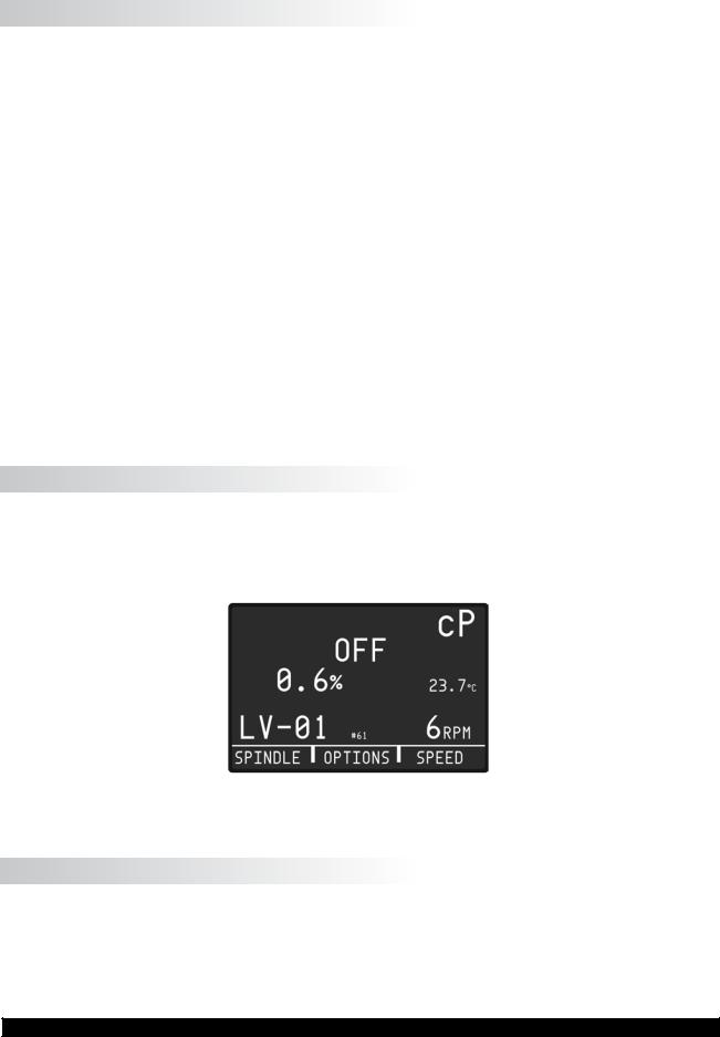
II.4 Home Screen
The DV1 Home screen is presented at the conclusion of AutoZero and can be accessed by selecting a Hot Key marked as HOME. The Home screen shows the measurement parameters chosen by the operator including: measured viscosity, temperature, %torque, motor status, spindle, and speed. The available Hot Keys on the Home screen include: SPINDLE, OPTIONS, and SPEED (see Figure II-2).
Figure II-2
II.5 Spindle Selection
DV1MLV Viscometers are provided with a set of four spindles and a narrow guardleg; DV1MRV Viscometers are provided with a set of six spindles and a wider guardleg; DV1MHA and DV1MHB Viscometers come with a set of six spindles and no guardleg (see Appendix F for more information on the guardleg).
Brookfield Engineering Laboratories, Inc. |
Page 15 |
Manual No. M14-023 |
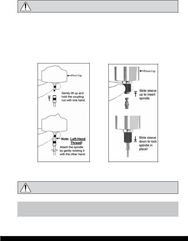
The spindles are attached to the viscometer by screwing them onto the coupling nut on the lower shaft (see Figure II-3). Note that the spindles have a left-hand thread. The lower shaft should be secured and slightly lifted with one hand while screwing the spindle to the left. The face of the spindle nut and the matching surface on the lower shaft should be smooth and clean to prevent eccentric rotation of the spindle. Spindles can be identified by the number on the side of the spindle coupling nut.
The motor should be OFF whenever spindles are being removed or attached.
If your instrument has the EZ-Lock system, the spindles are attached as follows:
With one hand, hold the spindle, while gently raising the spring-loaded outer sleeve to its highest position with the other hand, as shown in Figure II-4. Insert the EZ-Lock Spindle Coupling so that the bottom of the coupling is flush with the bottom of the shaft, and lower the sleeve. The sleeve should easily slide back down to hold the spindle/coupling assembly in place for use. [Spindles can be identified by entry code; look for the number on the side of the EZ-Lock spindle coupling.]
Figure II-3 |
Figure II-4 |
The motor should be OFF whenever spindles are being removed or attached.
NOTE: Keep the EZ-Lock Spindle Coupling and outer sleeve as clean as possible and free from debris that could become lodged inside the adapter.
Brookfield Engineering Laboratories, Inc. |
Page 16 |
Manual No. M14-023 |

The DV1 requires a Spindle Entry Code number to calculate viscosity values. The two-digit code for each spindle can be found in Appendix D.
Pressing the SPINDLE Hot Key on the Home screen will present the Set Spindle screen.
Figure II-5
Press the Up/Down Arrow keys to scroll through the list of available spindles. When the correct spindle number is shown on the display, press the SELECT Hot Key. The display will return to the Home screen.
The Set Spindle screen also includes the currently selected speed of rotation and the Full Scale Range of viscosity (FSR). The FSR represents the maximum viscosity value that can be measured with the currently selected spindle and speed combination. As the spindle number is changed, the FSR value will change to show the new condition. Each spindle and speed combination has a unique FSR.
TIP: The minimum viscosity measurement range is 10% of the FSR.
TIP: Full Scale Range is the same value as AutoRange.
TIP: The accuracy of viscometer measurement is expressed as a percentage of the Full Scale Range.
The Set Spindle screen includes three Hot Keys:
BACK: Return to the Home screen without changing the spindle selection. SELECT: Accept the spindle selection and return to the Home screen. SPEED: Accept the spindle selection and move to the Set Speed screen.
Brookfield Engineering Laboratories, Inc. |
Page 17 |
Manual No. M14-023 |

II.6 Speed Selection
Table II-1 shows the available speed selections.
DV1 SPEEDS SETS
|
|
100 |
|
|
50 |
|
|
|
|
|
20 |
|
|
10 |
|
|
5.0 |
|
|
4.0 |
|
|
2.5 |
|
|
2.0 |
|
|
1.0 |
|
|
0.5 |
|
|
0.0 |
|
|
60 |
|
|
30 |
|
|
12 |
|
|
6.0 |
|
|
3.0 |
When scrolling |
1.5 |
|
“UP” |
0.6 |
|
|
|
0.3 |
Beginning |
0.0 |
|
Table II-1
NOTE: DV1 speeds are organized to conform to the historical speed sets available on the Brookfield Dial Reading viscometer. Speeds from 0.3-60 RPM are traditionally found on the LVT viscometer. Speeds from 0.5-100 RPM are traditionally found on RVT, HAT and HBT viscometers.
Pressing the SPEED Hot Key on the Home screen will present the Set Speed screen.
Figure II-6
Press the Up/Down Arrow keys to scroll through the list of available speeds. When the correct speed is shown on the display, press the SELECT Hot Key. The display will return to the Home screen.
Brookfield Engineering Laboratories, Inc. |
Page 18 |
Manual No. M14-023 |

TIP: Speeds are grouped according to traditional LV and RV settings.
TIP: When setting a test procedure, be aware if the data must be compared to another site. If a comparison is required, it is best to utilize speeds that are traditionally associated with the torque range of the viscometer. This will ensure that all test sites will be able to reproduce the test method exactly.
The Set Speed screen also includes the currently selected spindle and the Full Scale Range of viscosity (FSR). The FSR represents the maximum viscosity value that can be measured with the currently selected spindle and speed combination. As the speed is changed, the FSR value will change to reflect the new condition. Each spindle and speed combination has a unique FSR.
TIP: The minimum viscosity measurement range is 10% of the FSR. TIP: Full Scale Range is the same value as AutoRange.
TIP: The accuracy of viscometer measurement is expressed as a percentage of the Full Scale Range.
The Set Speed screen include three Hot Keys:
BACK: Return to the Home screen without changing the speed selection. SELECT: Accept the speed selection and return to the Home screen. SPEED: Accept the speed selection and move to the Set Spindle screen.
II.7 Full Scale Range
The Full Scale Range (FSR) is a calculation of the maximum viscosity value that can be measured by a spindle and speed combination when used with the specific spring torque of the DV1 Viscometer. This value represents the measured viscosity which will be displayed when the instrument’s %torque reading is at 100. The FSR will be displayed during the spindle selection process and the speed selection process. The FSR value will change as the selected speed or spindle is changed and will be displayed in the viscosity measurement units selected by the user in the Options Menu (see Section
II.8).
Brookfield recommends that viscosity measurements be made only when the instrument’s %torque value is between 10 and 100. The FSR represents the maximum value that can be measured (100% on the Torque scale). The minimum viscosity that can be measured is 10% of the FSR (equivalent to 10 on the Torque scale).
The accuracy of the Brookfield viscometer is expressed as a percentage of the instrument’s Full Scale Range. When using the standard LV (61-64) and RV (2-7) spindles, the instrument’s accuracy is +/-1% of the Full Scale Range (see Section I.4).
Brookfield Engineering Laboratories, Inc. |
Page 19 |
Manual No. M14-023 |
 Loading...