


 Loading...
BROOKFIELD DIGITAL RHEOMETER
MODEL DV-III+ Operating Instructions
Manual No. M/98-211-A0701
Please record the Model and Serial Number of your viscometer. Having this information readily available will help us to assist you should there be any questions regarding your instrument.
Model No. ______________________
Serial No. ______________________
SPECIALISTS IN THE
MEASUREMENT AND
CONTROL OF VISCOSITY
BROOKFIELD ENGINEERING LABORATORIES, INC.
11 Commerce Boulevard, Middleboro, MA 02346-1031 USA
TEL 508-946-6200 or 800-628-8139 (USA excluding MA)
FAX 508-946-6262 INTERNET www.brookfieldengineering.com
Brookfield Engineering Laboratories, Inc. |
Page 1 |
Manual No. M/98-211-A0701 |
|
|
|

|
|
|
|
|
|
|
|
|
|
|
|
|
|
|
|
|
|
|
|
|
|
|
|
|
|
|
|
|
|
|
|
|
Contents |
|
|
|
|
|
|
|
|
|
||||||||
|
|
|
|
|
|
|
INTRODUCTION |
|
|
|
|
|
|
|
|
|
|
|
|
|
|
|
|
|
|
|
|
|
|
|
|
|
|
|
|
|
3 |
|||||||||||||
I. |
|
|
|
|
|
|
|
|
|
....................................................................................................... |
|
|
|
|
|
|
|
|
|
|
|
|
|
|
|
|
|
|
|
|
|
|
|
|
|
|||||||||||||||
|
|
|
|
I.1 |
Components ............................................................................................................. |
4 |
||||||||||||||||||||||||||||||||||||||||||||
|
|
|
|
I.2 |
Utilities ..................................................................................................................... |
5 |
||||||||||||||||||||||||||||||||||||||||||||
|
|
|
|
I.3 |
Specifications ........................................................................................................... |
5 |
||||||||||||||||||||||||||||||||||||||||||||
|
|
|
|
I.4 |
Data Retention .......................................................................................................... |
5 |
||||||||||||||||||||||||||||||||||||||||||||
|
|
|
|
I.5 |
Set-Up ...................................................................................................................... |
6 |
||||||||||||||||||||||||||||||||||||||||||||
|
|
|
|
I.6 |
Connections .............................................................................................................. |
9 |
||||||||||||||||||||||||||||||||||||||||||||
|
|
|
|
I.7 |
Key Functions ........................................................................................................ |
10 |
||||||||||||||||||||||||||||||||||||||||||||
|
|
|
|
|
||||||||||||||||||||||||||||||||||||||||||||||
II. |
|
|
|
GETTING |
|
|
|
|
|
|
|
STARTED |
|
|
............................................................................................... |
|
|
|
|
|
|
|
|
|
|
|
|
|
|
|
|
|
|
|
|
|
|
|
|
|
|
12 |
||||||||
|
|
|
|
II.1 |
Autozero ................................................................................................................. |
12 |
||||||||||||||||||||||||||||||||||||||||||||
|
|
|
|
II.2 |
Rheometer Display ................................................................................................. |
13 |
||||||||||||||||||||||||||||||||||||||||||||
|
|
|
|
II.3 |
Spindle Entry .......................................................................................................... |
15 |
||||||||||||||||||||||||||||||||||||||||||||
|
|
|
|
II.4 |
Direct Speed Entry ................................................................................................. |
16 |
||||||||||||||||||||||||||||||||||||||||||||
|
|
|
|
II.5 |
External Control ..................................................................................................... |
17 |
||||||||||||||||||||||||||||||||||||||||||||
|
|
|||||||||||||||||||||||||||||||||||||||||||||||||
III. |
|
|
|
MAKING |
|
|
|
|
|
VISCOSITY |
|
|
|
|
|
|
MEASUREMENTS |
|
|
|
.............................................................. |
|
|
|
|
|
|
|
|
|
|
|
19 |
|||||||||||||||||
|
|
|
|
III.1 |
Quick Start ............................................................................................................. |
19 |
||||||||||||||||||||||||||||||||||||||||||||
|
|
|
|
III.2 |
Preparation ............................................................................................................. |
19 |
||||||||||||||||||||||||||||||||||||||||||||
|
|
|
|
III.3 |
Selecting a Spindle/Speed ...................................................................................... |
20 |
||||||||||||||||||||||||||||||||||||||||||||
|
|
|
|
III.4 |
Multiple Data Points .............................................................................................. |
20 |
||||||||||||||||||||||||||||||||||||||||||||
|
|
|
|
III.5 |
Cleaning ................................................................................................................. |
20 |
||||||||||||||||||||||||||||||||||||||||||||
|
|
|||||||||||||||||||||||||||||||||||||||||||||||||
IV. |
|
|
|
|
|
PROGRAMMING |
|
|
|
|
THE |
|
DV |
- |
III+ |
|
AND |
|
|
|
ANALYSIS |
|
..................................................... |
|
|
|
|
|
|
|
|
21 |
||||||||||||||||||
|
|
|
|
IV.1 |
Programming Concept ........................................................................................... |
21 |
||||||||||||||||||||||||||||||||||||||||||||
|
|
|
|
IV.2 |
DV-III Speed/Time Pair Programming .................................................................. |
22 |
||||||||||||||||||||||||||||||||||||||||||||
|
|
|
|
IV.3 |
Bevis Programs ...................................................................................................... |
34 |
||||||||||||||||||||||||||||||||||||||||||||
|
|
|
|
IV.4 |
Choosing the Best Data Collection Method ........................................................... |
36 |
||||||||||||||||||||||||||||||||||||||||||||
|
|
|
|
IV.5 |
Data Analysis ......................................................................................................... |
37 |
||||||||||||||||||||||||||||||||||||||||||||
|
|
|
|
|
|
|
|
|
|
|
|
|
|
|
|
|
|
|
|
|
|
|
|
|
|
|
|
|
|
|
|
|
|
|
||||||||||||||||
V. |
|
|
|
OPTIONS |
|
|
|
................................................................................................................ |
|
|
|
|
|
|
|
|
|
|
|
|
|
|
|
|
|
|
|
|
|
|
|
|
|
|
|
|
|
|
|
|
|
|
|
|
|
40 |
||||
|
|
|
|
V.1 |
|
Set Up ..................................................................................................................... |
|
|
|
|
|
|
|
|
40 |
|||||||||||||||||||||||||||||||||||
|
|
|
|
V.2 |
|
........................................................................................................................ |
|
|
|
|
|
|
|
|
|
|
|
|
|
|
|
|
|
|
|
|
|
|
|
|
|
41 |
||||||||||||||||||
|
|
|
|
V.3 |
Alarms .................................................................................................................... |
42 |
||||||||||||||||||||||||||||||||||||||||||||
|
|
|
|
V.4 |
Set Temperature ..................................................................................................... |
43 |
||||||||||||||||||||||||||||||||||||||||||||
|
|
|
|
V.5 |
Data |
|
........................................................................................................................ |
|
|
|
|
|
|
|
|
|
|
|
|
|
|
|
|
|
|
|
|
|
|
|
|
|
43 |
|||||||||||||||||
|
|
|
|
V.6 |
Timed data collection ............................................................................................. |
44 |
||||||||||||||||||||||||||||||||||||||||||||
|
|
|
|
|
|
|
|
|
|
|
|
|
|
|
|
|
|
|
|
|
|
|
|
|
|
|
|
|
|
|
|
|
|
|
|
|
|
|
|
|
|
|
|
|
|
|
|
|
|
|
VI. |
|
|
|
|
RHEOLOADER |
|
|
|
|
|
USER'S |
|
|
|
|
MANUAL |
|
........................................................................ |
|
|
|
|
|
|
|
|
|
|
|
|
|
|
|
47 |
||||||||||||||||
|
|
|
|
VI.1 |
Description of B.E.V.I.S. Commands .................................................................... |
47 |
||||||||||||||||||||||||||||||||||||||||||||
|
|
|
|
VI. 2 |
Example Programs ................................................................................................. |
50 |
||||||||||||||||||||||||||||||||||||||||||||
APPENDIX A |
- |
|
|
Cone/Plate Rheometer Set-Up ..................................................................... |
52 |
|||||||||||||||||||||||||||||||||||||||||||||
APPENDIX B |
- |
|
|
Viscosity Ranges .......................................................................................... |
56 |
|||||||||||||||||||||||||||||||||||||||||||||
APPENDIX C |
- |
|
|
Variables in Viscosity Measurements |
.......................................................... 61 |
|||||||||||||||||||||||||||||||||||||||||||||
APPENDIX D |
- |
|
|
Spindle and Model Codes ............................................................................ |
63 |
|||||||||||||||||||||||||||||||||||||||||||||
APPENDIX E |
- |
|
|
Calibration Procedures ................................................................................ |
67 |
|||||||||||||||||||||||||||||||||||||||||||||
APPENDIX F |
- |
|
|
VS-27Y Clamp Assembly ............................................................................ |
74 |
|||||||||||||||||||||||||||||||||||||||||||||
APPENDIX G |
- |
|
|
|
DV-III+ to Computer Command Set |
.......................................................... 75 |
||||||||||||||||||||||||||||||||||||||||||||
APPENDIX H |
- |
|
|
Fault Diagnosis and Troubleshooting |
.......................................................... 77 |
|||||||||||||||||||||||||||||||||||||||||||||
APPENDIX I |
- |
|
|
Warranty Repair and Service ....................................................................... |
80 |
|||||||||||||||||||||||||||||||||||||||||||||
Brookfield Engineering Laboratories, Inc. |
Page 2 |
Manual No. M/98-211-A0701 |
|
|
|

I.INTRODUCTION
The Brookfield DV-III+ Programmable Rheometer measures fluid parameters of Shear Stress and Viscosity at given Shear Rates. Viscosity is a measure of a fluid’s resistance to flow. You will find a detailed description of the mathematics of viscosity in the Brookfield publication “More Solutions to Sticky Problems”, a copy of which was included with your DV-III+.
The principle of operation of the DV-III+ is to drive a spindle (which is immersed in the test fluid) through a calibrated spring. The viscous drag of the fluid against the spindle is measured by the spring deflection. Spring deflection is measured with a rotary transducer. The measuring range of a DV-III+ (in centipoise) is determined by the rotational speed of the spindle, the size and shape of the spindle, the container the spindle is rotating in, and the full scale torque of the calibrated spring.
There are four basic spring torque series offered by Brookfield:
|
Spring Torque |
|
Model |
dyne•cm |
mN•m |
LVDV-III+ |
673.7 |
0.0673 |
RVDV-III+ |
7,187.0 |
0.7187 |
HADV-III+ |
14,374.0 |
1.4374 |
HBDV-III+ |
57,496.0 |
5.7496 |
The higher the torque calibration, the higher the measurement range. The measurement range for each torque calibration may be found in Appendix - B.
All units of measurement are displayed according to either the CGS system or the SI system.
1.Viscosity appears in units of centipoise (shown as “cP”) or milliPascal-seconds (shown as mPa•s).
2.Shear Stress appears in units of dynes/square centimeter (“D/cm2”) or Newtons/square meter (“N/m2”).
3.Shear Rate appears in units of reciprocal seconds (“1/SEC”).
4.Torque appears in units of dyne-centimeters or Newton-meters (shown as percent “%” in both cases).
The equivalent units of measurement in the SI system are calculated using the following conversions:
|
SI |
|
CGS |
Viscosity: |
1 mPa•s |
= |
1 cP |
Shear Stress: |
1 Newton/m2 |
= |
10 dyne/cm2 |
Torque: |
1 N•m |
= |
107 dyne•cm |
References to viscosity throughout this manual are done in CGS units.
WARNING: Use of this instrument in a manner not specified by Brookfield may result in incorrect readings or instrument failure. Please read this manual prior to using the instrument.
Brookfield Engineering Laboratories, Inc. |
Page 3 |
Manual No. M/98-211-A0701 |
|
|
|

 I.1
I.1  Components


Component |
Part Number |
|
|
|
|
DV-III+ Rheometer |
depends on model |
|
Powerbase |
DVP-2Y |
|
includes: |
|
|
Leveling Screws (3) |
VS-3 |
|
Upright Rod |
VS-20 |
|
Jam Nut |
VS-21 |
|
Clamp Assembly |
VS-27Y |
|
Spindle Set with Case |
|
|
LVDV-III+ set of four spindles or |
SSL |
|
RVDV-III+ set of seven spindles or |
SSR |
|
HA/HBDV-III+ set of seven spindles |
SSH |
For Cone/Plate versions: a spindle wrench, one cone spindle and sample cup Part No. CPE-44Y replace the spindle set.
Power Cord |
|
for 115 VAC |
DVP-65 |
for 230 VAC |
DVP-66 |
RTD Temperature Probe |
DVP-94Y |
Ribbon Cable |
DVP-145 |
Guard Leg: |
|
LVDV-III+ |
B-20Y |
RVDV-III+ |
B-21Y |
Carrying Case |
DVP-71Y |
RHEOLOADER Software |
DVP-201Y |
Cable (DV-III+ to Computer) |
DVP-80 |
Operator Manual |
M/98-211 |
Please check to be sure that you have received all components, and that there is no damage. If you are missing any parts, please notify Brookfield Engineering or your local Brookfield agent immediately. Any shipping damage must be reported to the carrier.
Brookfield Engineering Laboratories, Inc. |
Page 4 |
Manual No. M/98-211-A0701 |
|
|
|

|
|
|
I.2 |
|
|
|
|
Utilities |
|
|
|
|
|
|
|
|
|
|
|
|
|
|
|
|
|
|
|
|
|
|
|
|
|
|
|
|
|
|
|
|
|
|
|
|
|
|
|
|
|
|
|
|
|
|
|
|
|
|
|
|
|
|
|
|
|
|
|
Autosensing Power Supply: |
|
|
|
|
|
|
|
|
|
|
|
|
|
|
|
|
|
||||||||||||||||||||||||||||||||||||||||||||
|
|
|
Input Voltage: |
|
|
|
|
|
90 - 260 VAC |
|
|
|
|
|
|
|
|
|
|
|
|
|
|
|
|
|
||||||||||||||||||||||||||||||||||||||
|
|
|
Input Frequency: |
|
|
|
|
|
50 - 60 Hz |
|
|
|
|
|
|
|
|
|
|
|
|
|
|
|
|
|
||||||||||||||||||||||||||||||||||||||
|
|
|
Power Consumption: Less than 220 UA |
|
|
|
|
|
|
|
|
|
|
|
|
|
|
|
|
|
||||||||||||||||||||||||||||||||||||||||||||
|
|
|
Power Cord Color Code: |
|
|
|
|
|
|
|
|
|
|
|
|
|
|
|
|
|
||||||||||||||||||||||||||||||||||||||||||||
|
|
|
|
|
|
|
|
|
|
|
|
|
|
|
|
|
|
|
|
|
|
|
|
|
|
|
|
|
|
|
|
|
|
|
|
|
|
|
|
|
|
|
|
|
|
|
|
|
|
|
|
|
|
|
|
|
|
|
|
|
|
|
|
|
|
|
|
|
|
|
|
|
|
|
|
|
|
|
|
|
|
|
|
|
|
|
|
|
|
|
United States |
|
|
|
|
|
|
|
Outside United States |
||||||||||||||||||||||||||||||
|
|
|
|
|
|
Hot (live) |
|
|
|
|
|
|
|
|
|
|
|
|
Black |
|
|
|
|
Brown |
||||||||||||||||||||||||||||||||||||||||
|
|
|
|
|
|
Neutral |
|
|
|
|
|
|
|
|
|
|
|
|
White |
|
|
|
|
Blue |
||||||||||||||||||||||||||||||||||||||||
|
|
|
|
|
|
Ground (earth) |
|
|
|
|
|
|
|
|
|
|
|
|
Green |
|
|
|
|
Green/Yellow |
||||||||||||||||||||||||||||||||||||||||
|
|
|
I.3 |
|
|
|
|
|
|
Specifications |
|
|
|
|
|
|
|
|
|
|
|
|
|
|
|
|
|
|
|
|
|
|
|
|
|
|
|
|
|
|
|
|
|
|
|
|
|
|
|
|
|
|
|
|
|
|
|
|
|
|
|
|
|
Speed Range: |
0.01-250 RPM, 0.01 RPM increments from 0.01 to 0.99 RPM, |
||||||||||||||||||||||||||||||||||||||||||||||||||||||||
|
|
|
|
|
|
|
|
|
|
|
|
|
|
|
|
|
|
|
|
|
|
|
|
|
0.1 RPM increments from 1.0 to 250 RPM |
|||||||||||||||||||||||||||||||||||
|
|
|
Viscosity Accuracy: |
± 1.0% of full scale range for a specific spindle running at a |
||||||||||||||||||||||||||||||||||||||||||||||||||||||||
|
|
|
|
|
|
|
|
|
|
|
|
|
|
|
|
|
|
|
|
|
|
|
|
|
specific speed. |
|
|
|
|
|
|
|
|
|
|
|
|
|
|
|
|
|
|
|||||||||||||||||
|
|
|
Temperature sensing range: |
- 100° C to 300° C (-148° F to 572° F) |
|
|||||||||||||||||||||||||||||||||||||||||||||||||||||||
|
|
|
Temperature accuracy: |
± |
|
1.0° C from -100° C to 150° C |
|
|||||||||||||||||||||||||||||||||||||||||||||||||||||
|
|
|
|
|
|
|
|
|
|
|
|
|
|
|
|
|
|
|
|
|
|
|
|
|
± |
|
2.0° C from +150° C to 300° C |
|
||||||||||||||||||||||||||||||||
|
|
|
Analog Torque Output: |
0 - 1 Volt DC (0 - 100% torque) |
|
|||||||||||||||||||||||||||||||||||||||||||||||||||||||
|
|
|
Analog Temperature Output: |
0 - 4 Volts DC (10mv / ° C) |
|
|||||||||||||||||||||||||||||||||||||||||||||||||||||||
|
|
|
Printer Output: |
Centronics, serial |
|
|
|
|
|
|
|
|
|
|
|
|
|
|
|
|
|
|
||||||||||||||||||||||||||||||||||||||
|
|
|
Computer Interface: |
RS232 |
|
|
|
|
|
|
|
|
|
|
|
|
|
|
|
|
|
|
||||||||||||||||||||||||||||||||||||||
|
|
|
Weight: |
Gross Weight: |
|
|
|
|
35 lbs. |
15.9 kg |
||||||||||||||||||||||||||||||||||||||||||||||||||
|
|
|
|
|
|
|
|
|
|
|
|
|
|
|
|
|
|
|
|
|
|
|
|
|
Net Weight: |
|
|
|
|
32 lbs. |
14.5 kg |
|||||||||||||||||||||||||||||
|
|
|
Carton Volume: |
2.0 cu. ft. |
|
|
|
|
0.057 m3 |
|
||||||||||||||||||||||||||||||||||||||||||||||||||

 I.4
I.4  Data Retention


The DV-III+ will save spindle parameters (used to calculate centipoise, shear rate and shear stress), default settings and the test data from the last program test run when the rheometer is turned off or there is a power failure.
Brookfield Engineering Laboratories, Inc. |
Page 5 |
Manual No. M/98-211-A0701 |
|
|
|


 I.5
I.5  Set-Up


1)Place the upright rod into the hole at the front of the base. The rack gear and clamp assembly should face the rear of the base (see Figure 1). The upright rod is held in place with the jam nut which is attached from the bottom of the base. Tighten this nut with a suitable wrench (spanner).
VS-35 |
VS-40Y |
GEAR SCREW |
|
UNIVERSAL |
ASSEMBLY |
CLAMP |
|
VS-41Y
CLAMP KNOB
ASSEMBLY
VS-29
TENSION
INSERT
50S044012E140 |
VS-28 |
|
TENSION |
||
4-40 x 3/8 LG. |
||
SCREW |
||
SOC. HD. CAP SCREW |
||
|
VS-29W
WASHER (2 REQ'D.)
VS-34
UPRIGHT ROD
BASE UNIT
502020032S34Z WASHER, EXT. TOOTH, 5/16 O.D. x 5/32 I.D.
50S311B24S06B, SCREW,
5/16 - 18x3/8 LG. SLT. PAN HD.
Figure 1
Brookfield Engineering Laboratories, Inc. |
Page 6 |
Manual No. M/98-211-A0701 |
|
|
|

2)Insert the mounting handle on the back of the DV-III+ into the hole on the clamp assembly (Figure 2).
Bubble Level
Rack Gear
Clamp Screw 


Clamp Assembly
Upright Rod
Mounting Handle
Figure 2
3) Tighten the DV-III+ clamp Screw (Figure 2).
Note: If the clamp assembly moves along the upright rod too freely, tighten the tension screw (see Appendix F).
4)Insert the ribbon cable into the DV-III+ Rheometer head. Insert the other end of the ribbon cable into the connector on the DV-III+ base (see Figure 3).
Brookfield Engineering Laboratories, Inc. |
Page 7 |
Manual No. M/98-211-A0701 |
|
|
|

Rheometer Head
RTD Temperature
Probe Connector
Power ON/OFF Switch |
|
|
|
Ribbon Cable |
|
|
|
|
|
|
|
|
|
||||
|
|
|
|
|||||
|
|
|
||||||
|
|
|
|
|
|
|||
|
|
|
|
|
|
|
|
|
AC Fuse(s) |
|
|
|
|
Connector |
|||
|
|
|
|
|
RS-232 Serial |
|
|
|
|
|
|
|
|
Printer/Computer |
|||
AC Power Connector |
|
|
Analog Output(s) |
|||||
|
|
|||||||
|
|
|
|
|
|
|||
|
|
|
|
|
|
|
|
|
100-240 VAC 50/60 HZ 220VA |
MODEL DV-III BASE UNIT |
240 CUSTHING ST. |
STOUGHTON, MA USA 02072 |
Connector |
Connector |
Parallel Printer |
Ribbon Cable |
Figure 3
5)Connect the RTD probe to the socket on the back side of the DV-III+ Rheometer (Figure 3).
6)The Rheometer must be leveled before the instrument is zeroed and readings are taken. The level is adjusted using the three leveling screws on the base. Adjust so that the bubble level on top of the DV-III+ (Figure 2) is centered within the circle.
7)Make sure that the AC power switch at the rear of the base unit is in the OFF position. Connect the AC plug to the socket on the back of the DV-III+ base and plug it into the appropriate AC line.
The DV-III+ must be earth grounded to ensure against electronic failure!!
8)Temperature monitoring is assured (after the instrument has stabilized) to within ± 1.0° C in the range -100° C to +150° C and within 2° C in the range 150° C to 300° C.
9)For Cone/Plate models refer to Appendix A.
10)For printers, software and temperature controllers, refer to Section 1.6, Connections.
Brookfield Engineering Laboratories, Inc. |
Page 8 |
Manual No. M/98-211-A0701 |
|
|
|

 I.6
I.6  Connections


The DV-III+ Rheometer is capable of communicating with several external devices to enhance operation. The cables and connections required for proper communication are detailed below.
RHEOLOADER SOFTWARE
DVP-80 cable is used to connect the RS232 serial port on the DV-III+ base to Com Port 1 or Com Port 2 on the computer. This cable is supplied with the DV-III+.
RHEOCALC SOFTWARE
DVP-80 cable is used to connect the RS232 serial port on the DV-III+ base to Com Port 1 or Com Port 2 on the computer. This cable is supplied with the RHEOCALC software.
PARALLEL PRINTER
CAP-86 cable is used to connect the 25-pin parallel port on the DV-III+ base with the Centronics port on the printer.
SERIAL PRINTER
DVP-81 cable is used to connect the 9-pin serial port on the DV-III+ with the 25-pin serial port on a printer.
THERMOSEL CONTROLLER, MODEL HT-106
TC-200/TC-500/TC-201P/TC-501P BATH, MODEL HT-107
DVP-141 cable is used to connect the serial port on the DV-III+ base to the serial port on the controller. This cable is supplied with the controller/bath.
Be sure that the controller temperature probe is properly located in the control device (Thermosel or bath) and connected to the controller.
Notes: 1. The controller may alternately communicate with Rheocalc V 2.0 software. In this configuration, the controller is connected to the computer through either Com Port 1 or Com Port 2. The DV-III+ is also connected to a computer Com Port.
2.The controller must also be connected to the control device (Thermosel or bath) with the appropriate load cable.
STRIP CHART RECORDER
DVP-96Y cable is used to connect the serial port on the DV-III+ to the input block of the strip chart recorder. This cable is supplied with a Brookfield strip chart recorder.
Brookfield Engineering Laboratories, Inc. |
Page 9 |
Manual No. M/98-211-A0701 |
|
|
|


 I.7
I.7  Key Functions


Figure 4 shows the control keys on the face of the DV-III+ Rheometer. The following describes each key’s function.
MOTOR |
AUTO |
7 |
8 |
9 |
|
ON/OFF |
|||||
RANGE |
|||||
|
|
|
|
||
ESCAPE |
|
|
|
|
|
OPTION |
PROG |
4 |
5 |
6 |
|
TAB |
|||||
SELECT |
PROG |
1 |
2 |
3 |
|
SPDL |
RUN |
YES |
NO |
||
|
|
|
|||
SELECT |
. |
0 |
ENTER |
||
DISP |
Figure 4
MOTOR ON/OFF ESCAPE
AUTO RANGE
MOTOR ON/OFF, ESCAPE
Turns the motor on or off. Cancels any operation, returns the user to the previous screen.
AUTORANGE
Presents the maximum (100% torque) viscosity attainable using the selected spindle at the current speed.
SELECT
SPDL
SELECT
DISP
SELECT SPDL
Allows selection of the spindle to be used.
SELECT DISP
Selects the parameter to be displayed:
% Rheometer Torque (%) cP Viscosity (cP or mPa.s)
SS Shear Stress (Dynes/cm2 or Newtons/m2) SR Shear Rate (1/Sec)
OPTION TAB

OPTION, TAB
Accesses options menu. See Section V. Toggles between selectable items when indicated.
Sends a single line of data to an attached printer. Selects printing and non-printing mode as selected in the Options menu.
Brookfield Engineering Laboratories, Inc. |
Page 10 |
Manual No. M/98-211-A0701 |
|
|
|
PROG
PROG
RUN
PROG
Access the Programs menu for program creation, running or deleting. Contstructs a test program. Allows you to review/modify an existing test program. Execute a Bevis program.
PROG RUN
Execute DV-III speed/time pair program.
0NUMBER KEYS (0 through 9)
Sets speeds and choose items from various dialog screens and the option menu.
ENTER ENTER
Functions as an ENTER key similar to a computer by serving to accept a keyboard entry.
Brookfield Engineering Laboratories, Inc. |
Page 11 |
Manual No. M/98-211-A0701 |
|
|
|

II. GETTING STARTED

 II.1
II.1 Autozero


Before readings may be taken, the Rheometer must be autozeroed. This is done each time the power switch is turned on. The Rheometer will guide you through the procedure, as follows:
Turn power switch on; as shown in Figure 5, the screen indicates that the DV-III+ is in the standalone mode (is not connected to a computer) and gives the version of the operating firmware (the built in program which controls the instrument) and a two-digit alphanumeric code which indicates the Model number (see Table D2 in Appendix D; the code tells the spring torque rating of your Rheometer).
Figure 5
No key press is necessary. After a short pause the display will read “REMOVE SPINDLE, LEVEL RHEOMETER AND PRESS THE MOTOR ON/OFF KEY TO AUTOZERO.” Before beginning the autozero procedure, Brookfield recommends that you allow 10 minutes for the instrument to warm up.
After pressing the MOTOR ON/OFF key, the screen “flashes” for approximately 15 seconds while the DV-III+ autozeros.
After 15 seconds the display reads “AUTOZERO IS COMPLETE REPLACE SPINDLE AND PRESS ANY KEY.” Press a key.
The main screen is displayed and the DV-III+ is ready for use (Figure 6).
Figure 6
Brookfield Engineering Laboratories, Inc. |
Page 12 |
Manual No. M/98-211-A0701 |
|
|
|
 II.2
II.2 Rheometer
 Display
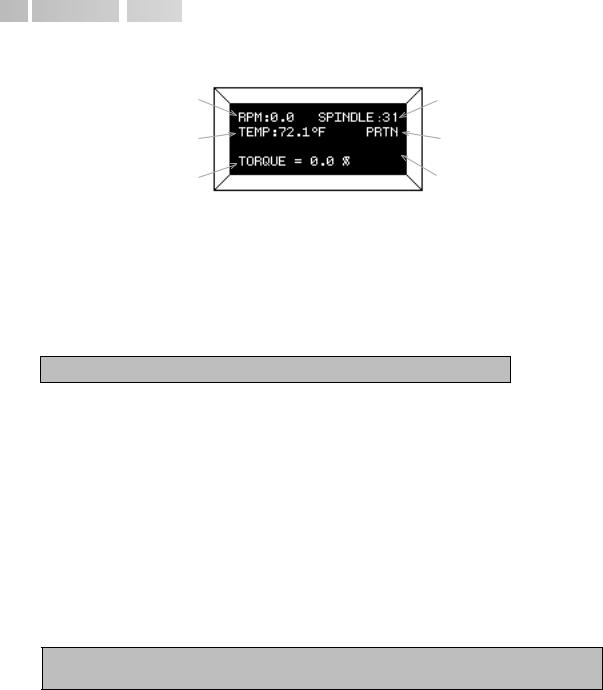


The DV-III+ Rheometer is supplied with a 4-line display. The basic set of information is called "The Default Screen" and is shown in FIGURE 7. The parameters are detailed below:
1 |
2 |
3 |
4 |
5 |
6 |
Figure 7
1.Motor Status and Current Rheometer Speed
The DV-III+ motor can be OFF, ON at 0.0 rpm or ON at a speed greater than 0.0 rpm. When the motor is OFF, "OFF" will be displayed and no speed entry will be accepted. When the motor is ON, the actual speed of rotation will be displayed. When the motor is switched from ON to OFF, the speed of rotation will be remembered; when the motor is turned ON again, the DV-III+ will operate at that same speed. The rheometer motor is set to "OFF" after AUTOZERO.
Note: Motor OFF and a speed setting of 0.0 are essentially the same.
2.Spindle Number
The currently-selected spindle. Viscosity, shear rate, and shear stress values will be calculated based on this number. See Section II.3.
3.Measured Temperature
The current temperature as measured by the attached temperature probe. If no probe is connected, four dashes "----" will be displayed.
4.Printing Status
Indicates the currently-selected method of printing. See Section II.5.
5.Measured Data
Instrument Torque (%), Viscosity (cP), Shear Stress (D/cm2), Shear Rate (s-1) The parameters are toggled from one to another using the Select Display key.
Note: Shear Stress and Shear Rate data cannot be calculated for some spindle geometries. In these cases, the display will show 0.0.
6.Blank Line
This line is used to display entry data when selecting a spindle or speed of rotation. Additionally, selected programs available for running will be identified here when in the Program mode. (See Section IV.2).
The default screen will appear at the completion of the AUTOZERO sequence each time the DVIII+ is turned ON in the standalone mode (see Section II.6 for external control mode). The displayed data may be changed as described in the following sections.
The format for data displayed in the default screen and all other screens is described in Table 1. For appearance sake, the entries in the table have been decimal point aligned. Actual rheometer display will have all fields left justified.
Brookfield Engineering Laboratories, Inc. |
Page 13 |
Manual No. M/98-211-A0701 |
|
|
|
|
I t e m |
P r i n t |
|
F o r m a t |
|
Range |
|
Example |
|
||
|
|
|
|
|
|||||||
|
|
|
|
|
|
|
|
|
|
|
|
|
R P M |
|
R P M |
|
X.XX |
0.01 |
<= RPM |
<= |
0.99 |
0.09 |
|
|
|
|
|
|
XX.X |
0.1 |
<= RPM |
<= |
99.9 |
2.4 |
|
|
|
|
|
|
XXX.X |
100 |
<= RPM |
<= |
250 |
150.0 |
|
|
M o d e l |
|
M |
|
XXXXX |
See Model Table D2 - App D |
RV |
|
|||
|
Spindle |
S |
|
XX |
00 |
<= S |
<= |
99 |
31 |
|
|
|
T o r q u e |
|
T |
|
XX.X |
-10.1 |
<= T |
<= |
99.9 |
82.4 |
|
|
V i s c o s i t y |
cP or mPas |
X.XX |
0 |
<= cP |
<= |
9.99 |
3.16 |
|
||
|
|
|
|
|
XXX.X |
10 |
<= cP |
<= |
999.9 |
123.8 |
|
|
|
|
|
|
XXXXX |
1000 |
<= cP |
<= |
99999 |
12345 |
|
|
|
|
|
|
XXXeX |
100000 |
<= cP |
<= |
51200000000 |
123e3 to 8 |
|
|
Shear |
Stress |
D/CM2 |
or |
X.XX |
0 |
<= D/CM2 <= |
9.99 |
4.56 |
|
|
|
|
|
N/M2 |
= |
XXX.X |
10 |
<= D/CM2 <= |
999.9 |
234.5 |
|
|
|
|
|
D / C M 2 / 1 0 |
XXXXX |
1000 |
<= D/CM2 <= |
99999 |
12345 |
|
||
|
|
|
|
|
XXXeX |
100000 |
<= D/CM2 <= 999999 |
123e3 |
|
||
|
Shear |
Rate |
1 / S E C |
|
X.XXX |
0 <= 1/SEC <= 9.999 |
1.234 |
|
|||
|
|
|
|
|
XX.X |
10 |
<= 1/SEC <= |
99.9 |
20.7 |
|
|
|
|
|
|
|
XXXXX |
100 |
<= 1/SEC <= |
99999 |
200 |
|
|
|
T e m p e r a t u r e |
T |
|
XXX.X |
-99.9 <= T |
<= |
300.0 |
-10.3 |
|
||
|
|
|
|
|
|
|
|
|
|
||
|
Tiime |
|
Z |
|
XX:XX |
00:00 <= Z |
<= 99.59 |
05:32 |
|
||
|
|
|
|
|
|
|
|
|
|
|
|
Table 1
OUT OF RANGE INDICATORS
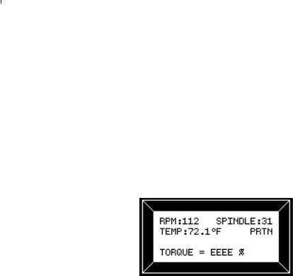
The DV-III+ is capable of measuring instrument torque within the range of 0 to 100%. Based on this measurment, viscosity and shear stress are calculated. Brookfield recommends that data be collected only in the range of 10 to 100%. Any data collected outside of this range is considered invalid.
The DV-III+ provides the following display indicators when the measurement point is outside of the 10-100% acceptable range.
TORQUE GREATER THAN 100%
When Rheometer torque exceeds 100%, the parameter display field will show “EEEE” for torque, viscosity and shear stress.
Figure 8
TORQUE LESS THAN 10%
When Rheometer torque drops below ten (10) percent, the Rheometer will continue to display measurement (%, cP, D/cm2) values with units flashing:
Brookfield Engineering Laboratories, Inc. |
Page 14 |
Manual No. M/98-211-A0701 |
|
|
|
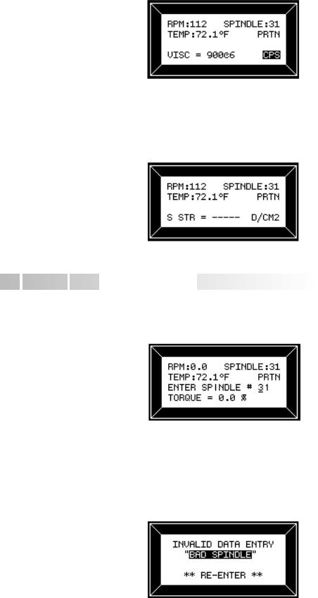
Figure 9
TORQUE LESS THAN 0%
When Rheometer torque drops below zero (0) percent, the Rheometer will continue to display torque values preceded by a minus (-) sign. The viscosity and shear stress field will display dashes (- - - - ) as indicated in the next screen display:
Figure 10
 II.3
II.3 Spindle
  Entry
Entry 


The user can elect to change the spindle selection by pressing the SELECT SPDL key. The DV-III+ control program will use the previously blank line 3 on the default display screen to record the new spindle input as depicted in Figure 11.
Figure 11
To enter a spindle number, press the numeric keys until the desired spindle number has been entered. Valid spindle numbers encompass the range from 00 to 99 as listed in Appendix D. Mistakes are corrected by repeatedly pressing the numeric keys until the proper spindle value has been entered. At that point, the user presses the SELECT SPDL key again. An invalid spindle entry will result in a “beep” and the display of the data entry error screen as depicted below.
Figure 12
Brookfield Engineering Laboratories, Inc. |
Page 15 |
Manual No. M/98-211-A0701 |
|
|
|

An invalid spindle entry is any two digit number in the range from 01 to 99 which is not listed in Appendix D. This error message will be displayed for a few seconds after which the spindle entry screen (Figure 11) will be re-displayed with a blank field for the spindle number. The user can cancel spindle entry at any time by pressing the MOTOR ON/OFF/ESCAPE key.
The user may elect to use a special spindle whose selection is accomplished by first entering a spindle number of 99 and then pressing the SELECT SPDL key. This will result in the following display:
Figure 13
At this point, press the numeric key for the special spindle of choice. This list is created at the time the Rheometer is manufactured. This list will therefore depend on the number of special spindles ordered and could contain as few as one (1) or as many as five (5) spindles. If no special spindles were purchased, the following message will be displayed if 99 is entered for a spindle number:
Figure 14
Press any key to exit this screen and to return to the spindle selection screen. The user may again select another spindle or press the SELECT SPDL key to cancel spindle selection operation.
Successful selection of a spindle at the press of the SELECT SPDL key returns the user to the default screen with the new spindle displayed in the upper right-hand corner. For standard spindles this would be the two (2) digit designator used to select the spindle. In the case of special spindles, the two (2) letters (AA, AB, AC, AD or AE) corresponding to the special spindle would be displayed instead. The spindle number or letters will be retained in memory when power is removed. This means that the last value entered for the spindle will be displayed the next time the Rheometer is turned on.

 II.4
II.4 Direct
 Speed Entry


At this point, the user may choose to enter a speed by the so-called direct speed entry method. Enter a valid speed in the range of 0.01 to 250 RPM by pressing the numeric keys successively. The previously blank line 3 on the default display screen records the user’s new speed input as depicted in Figure 15:
Brookfield Engineering Laboratories, Inc. |
Page 16 |
Manual No. M/98-211-A0701 |
|
|
|
Figure 15
Here, the user intends to enter a speed of 112 RPM, has pressed the “1” key twice and is about to press the “2” key. If the user makes more than five (5) key presses, the DV-III+ control program will “roll” the cursor back to the first character of the field and begin to overwrite the previous data entry.
Next the user presses the ENTER key to accept the speed. The motor will begin running at 112 RPM and the display will be updated to the next screen image:
Figure 16
If the speed entered was not valid the Rheometer will display the following message:
Figure 17
After a few seconds, the display returns to Figure 15 with the speed data field cleared and just the underscore cursor awaiting a new entry.
 II.5
II.5 External
 Control


The DV-III+ Rheometer can be used in conjunction with Brookfield software, RHEOCALC (V. 2. or higher). Through RHEOCALC, all rheometer functions are controlled by the computer. The DVIII+ must be set to the external control mode to allow for proper communication with RHEOCALC. To configure the external control mode, connect cable DVP-80 to the serial port on the DV-III+ base before turning on the DV-III+. With the DVP-80 cable in place, the DV-III+ will present the screen shown in Figure 18 when it is turned on. If external control is selected, the DV-III+ will display Figure 19 and only accept control commands from RHEOCALC software.
Brookfield Engineering Laboratories, Inc. |
Page 17 |
Manual No. M/98-211-A0701 |
|
|
|
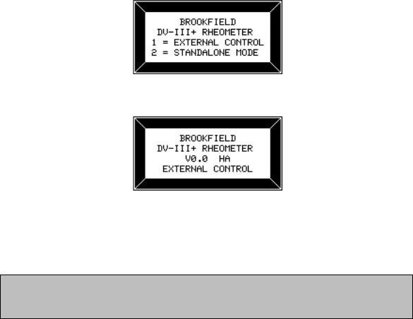
Figure 18
Figure 19
The DV-III+ may be set to stand alone mode by turning it OFF and ON again and selecting "Stand Alone" or by removing the DVP-80 cable prior to turning the DV-III+ on.
Note: The DV-III+ cannot communicate with RHEOLOADER software in the external control mode. Chose "Stand Alone" when presented with Figure 18 if you want to use RHEOLOADER.
Brookfield Engineering Laboratories, Inc. |
Page 18 |
Manual No. M/98-211-A0701 |
|
|
|

III. MAKING VISCOSITY MEASUREMENTS
 III.1 Quick
  Start
Start 


The DV-III+ Rheometer uses the same methodology as the Brookfield Dial Reading Viscometer and DV series of Digital Viscometers. If you have experience with other Brookfield equipment, this section will give you the quick steps for taking a viscosity reading. If you have not used a Brookfield Viscometer before, skip this section and go to Section III.2 for a detailed description.
A)Assemble and level the rheometer (Section I.5).
B)Autozero the rheometer (Section II.1).
C)Enter the spindle number using the SELECT SPINDLE key (Section II.3).
D)Introduce the spindle into the sample and attach the spindle to the coupling nut.
NOTE: Left-hand threads.
E)Enter the speed of rotation using the number pad and ENTER key (Section 11.4).
F)Record % torque and viscosity.
 III.2 Preparation


A)RHEOMETER: The DV-III+ should be turned on, leveled and autozeroed. The level is adjusted using the three feet on the bottom of the base and confirmed using the bubble on the top of the head. Adjust the feet until bubble is inside the center target. Set the level prior to autozero and check the level prior to each measurement.
Proper level is essential for correct operation of the DV-III+.
B)SAMPLE: The fluid to be measured (sample) must be in some container. Many spindle systems from Brookfield are supplied with specific sample chambers such as the Small Sample Adapter, UL Adapter and Thermosel. The standard spindles supplied with the DV-III+, LV (1-4), RV (1-7) and HA/HB (1-7), are designed to be used with a 600ml low form Griffin beaker (or equivalent container with a diameter of 8.25 cm).
Brookfield recommends that you use the appropriate container for the selected spindle. You may choose to use an alternate container for convenience, however, this may have an effect on the measured viscosity. The DV-III+ is calibrated considering the specified container. Alternate containers will provide results that are repeatable but not "true."
The LV (1-4) and RV (1-7) are designed to be used with the guardleg attached. Measurements made without the guardleg will provide repeatable results but may not provide "true" results.
When comparing data with others, be sure to specify the sample container and presence/ absence of the guardleg.
Many samples must be controlled to a specific temperature for viscosity measurement. When conditioning a sample for temperature, be sure to temperature control the container and spindle as well as the sample.
Please see our publication, "More Solutions to Sticky Problems", for more detail relating to sample preparation.
Brookfield Engineering Laboratories, Inc. |
Page 19 |
Manual No. M/98-211-A0701 |
|
|
|


 III.3 Selecting a Spindle/Speed


The DV-III+ has the capability of measuring viscosity over an extremely wide range (for example, the RVDV-III+ can measure fluids within the range of 100-40,000,000 cP) (see Appendix B). This range is achieved through the use of several spindles over many speeds.
The process of selecting a spindle and speed for an unknown fluid is normally trial and error.
An appropriate selection will result in measurements made between 10-100 on the instrument % torque scale. Two general rules will help in the trial and error process.
1)Viscosity range is inversely proportional to the size of the spindle.
2)Viscosity range is inversely proportional to the rotational speed.
In other words: to measure high viscosity, choose a small spindle and/or a slow speed. If the chosen spindle/speed results in a reading above 100%, then reduce the speed or choose a smaller spindle.
Experimentation may reveal that several spindle/speed combinations will produce satisfactory results between 10-100%. When this circumstance occurs, any of the spindles may be selected.
Non-Newtonian fluid behavior can result in the measured viscosity changing if the spindle and/ or speed is changed. See our publication, "More Solutions to Sticky Problems," for more detail.
When viscosity data must be compared, be sure to use the same spindle, speed, container and temperature.

 III.4 Multiple
  Data Points


The majority of viscosity measurements are made at the quality control level and consist of a single data point. The test is conducted with one spindle at one speed. The data point is a useful bench mark for the go/no-go decision in a production setting. The DV-III+ can be used for single point measurement.
Many fluids exhibit a characteristic change in viscosity with a change in applied force. This non-Newtonian flow behavior is commonly seen in paints, coatings and food products as a decrease in viscosity as shear rate increases. This behavior cannot be detected or evaluated with the single viscosity point measurement.
Non-Newtonian flow is analyzed through the collection of viscosity data over a range of shear rates and the generation of a graph of viscosity versus shear rate (a rheogram). This information will allow for a more complete characterization of a fluid and may help in formulating and production of the product. The DV-III+ is capable of collecting multiple data points for the analysis of flow behavior. See Section IV on Programming and Analysis.
More information on flow behavior, shear rate and rheograms is available in our publication, "More Solutions to Sticky Problems."

 III.5 Cleaning


All immersed components are stainless steel. Use cleaning solutions that are not corrosive and avoid scratching the measurement surfaces. The instrument housing should be cleaned with a soft damp cloth.
Brookfield Engineering Laboratories, Inc. |
Page 20 |
Manual No. M/98-211-A0701 |
|
|
|
IV. PROGRAMMING THE DV-III+ AND ANALYSIS
The programming and data analysis functions of the DV-III+ are accessed by pressing the PROG key on the rheometer. The display will change to present a menu with three choices: DV-III, B.E.V.I.S., and Models. DV-III and B.E.V.I.S. are the programming alternatives. Models will present the five math models available for data analysis.
Figure 20
 IV.1
IV.1 Programming
 Concept


The DV-III+ may be programmed to collect viscosity data without operator involvement. The captured data may be displayed and analyzed or output to a printer. Programs may be written using two different methodologies, DV-III and B.E.V.I.S.
The DV-III programming technique uses speed/time pairs to control the DV-III+. A program consists of multiple lines (up to 25) instructing the rheometer to operate at a particular speed for some period of time. As an example, we can instruct the DV-III+ to rotate the spindle at 5 RPM for 30 seconds and then change speed to 10 RPM and wait 20 seconds with the following program:
Step 1 |
RPM = 5 |
Time = 00:30 |
Step 2 |
RPM = 10 |
Time = 00:20 |
A single data point will be collected at the end of each time interval.
The B.E.V.I.S. programming technique uses a custom program language to control the DV-III+. A program consists of a series of commands instructing the rheometer in speed control, time control, data collection, temperature control, and output. B.E.V.I.S. offers a higher level of rheometer control compared to the DV-III method. However, the construction of B.E.V.I.S programs is more involved. The 2-step DV-III program previously described is duplicated using B.E.V.I.S. commands below:
SSN |
5 |
WTI |
00:30 |
PDN |
|
SSN |
10 |
WTI |
00:20 |
PDN |
|
END |
|
The involved programming of B.E.V.I.S. commands is a small trade for the significant increase in control capability over the DV-III method.
Brookfield Engineering Laboratories, Inc. |
Page 21 |
Manual No. M/98-211-A0701 |
|
|
|


 IV.2
IV.2  DV-III Speed/Time
 Pair Programming


This programming method allows the operator to control the DV-III+ through the variables of speed and time. These speed/time pairs instruct the rheometer to operate at a speed of rotation for a certain period of time. Programs can be created with up to 25 steps. The DV-III+ can store up to 10 programs. Upon completion of a program, the data may be viewed on the DV-III+ display, analyzed or printed to an attached parallel or serial printer.
Two examples of programs are shown below:
Collect Data Over Time |
Collect Data At Several Speeds |
||||
Step |
RPM |
Time |
Step |
RPM |
Time |
1 |
100 |
00:12 |
1 |
2.5 |
01:00 |
2 |
100 |
00:12 |
2 |
5 |
00:30 |
3 |
100 |
00:12 |
3 |
10 |
00:30 |
4 |
100 |
00:12 |
4 |
20 |
00:15 |
5 |
100 |
00:12 |
5 |
50 |
00:15 |
Five viscosity data points will be collected over one minute.
Five viscosity data points will be collected at five speeds over 150 seconds.
This program mode is accessed by pressing the program key and selecting number 1; 1 = DV-III. The creation, editing and execution of DV-III programs are described in the following sections.
There are two types of test programs:
1)Next Speed Set where the test speeds are programmed, and the operator must signal the DVIII+ to change speeds (and therefore take a reading) by pressing the ENTER key.
2)Prog Speed Set where the DV-III+ will perform the test automatically.
Each step of a program has two variables - speed and hold time. The reading is taken at the end of the hold time interval in a Prog Speed Set or when the ENTER key is pressed in a Next Speed Set.
If the first step hold time interval is 0 seconds, the program is a Next Speed Set type. If the first step interval is 1 second or more, the program is a Prog Speed Set type.
SPEED SET SELECTION AND PROGRAMMING
The DV-III+ viscometer allows for the retention of a maximum of 10 speed sets with up to 25 discrete speeds per speed set. The program locations are numbered 0 through 9. These speed sets are retained in EEPROM memory for those times when the DV-III+ is not powered up. To access a previously programmed speed set or to enter data for a new speed set, the user presses the “1” key when in the display of Figure 20 and is presented with the screen shown in Figure 21:
Brookfield Engineering Laboratories, Inc. |
Page 22 |
Manual No. M/98-211-A0701 |
|
|
|
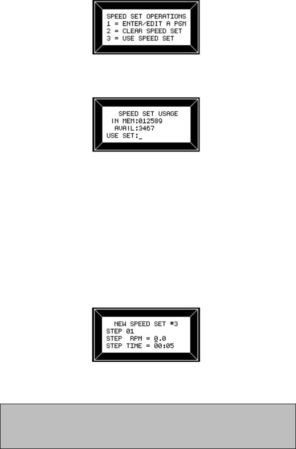
Figure 21
At this point, the user may Enter/Edit, Clear or Use a stored program (Speed Set). Let’s startwith Enter/Edit by pressing the “1” key:
Figure 22
In this example, the user is informed that he has 6 speed sets (0,1,2,5,8,9) pre-programmed in memory and 4 speed sets (3,4,6,7) not programmed and available. Select any one of the ten speed sets by pressing the appropriate numeric key. Pressing the MOTOR ON/OFF/ESCAPE key at this point would exit the user to the default PROGRAM MODES display (Figure 20). For now let’s assume that the user wants to program a new speed set by pressing the “3” key (the first available program slot).
ENTERING A SPEED SET (PROGRAM)
There are two (2) types of programs available to the user: programs with finite step time intervals and programs with zero (0) step time intervals. We will cover the inputting of finite step time programs first.
SPEED SETS WITH FINITE STEP TIMES (PROG SPEED)
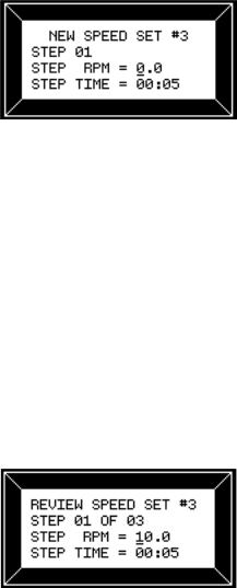
These programs when executed will automatically progress from step intervals programmed by the user. On pressing the “3” key in Figure 22
to step based on the time the user is presented with:
Figure 23
This screen reminds the user of the speed set that he has selected to program and then allows him to change either the speed or time interval or both for that step.
Note: The time interval on entry to this screen will always be set to 00:05 seconds as the default value. The user may of course change it to any valid time of his choice. Whenever you change time interval, that new time becomes the default interval until it is again changed by the user. Also, note that zero (0) times are not allowed for program steps after the first step for Finite Step programs.
Brookfield Engineering Laboratories, Inc. |
Page 23 |
Manual No. M/98-211-A0701 |
|
|
|
The OPTION/TAB key is used for moving from input field to input field and the ENTER key to accept the current input for a step. On entry to this screen, the underscore cursor would be flashing (as shown) under the first digit of the step RPM. Use the numeric keys to make changes to the step speed, repeating the input as many times as required until satisfied.
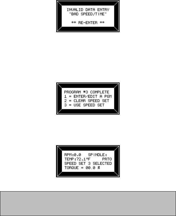
When satisfied with the speed input, press the OPTION/TAB key which moves the flashing cursor down to the first character of the time field. The same procedure is used here to input the step time as was used to enter the RPM above. Speed or time data that is out of range, as defined by Table 1, will result in the following screen:
Figure 24
This screen will be displayed for 1-3 seconds.
When ready, the user may press the PROG RUN key to display the data for the next step in the program, or the MOTOR ON/OFF/ESCAPE key (whereby none of the changes up to that point will be accepted) to return to the screen of Figure 22. To end a program, the user simply enters and accepts a step RPM and Time of zero (0) or continues to input step data until the program reaches the twentyfive (25) step program limit. In either case, the following screen will be displayed:
Figure 25
To use the currently selected speed set, press the “3” key in Figure 25. This would immediately revert to the default screen modified as follows:
Figure 26
Note: If at this point, prior to using the program the user wished to enter a direct speed, a press of any numeric key which would result in a display similar to Figure 15. At the completion of the direct speed input, the display would revert to Figure 26 above with the appropriate RPM displayed, and the viscometer running at that speed.
Brookfield Engineering Laboratories, Inc. |
Page 24 |
Manual No. M/98-211-A0701 |
|
|
|
The program is initiated by pressing the PROG RUN key. See "Using Pre-programmed Speeds."
SPEED SETS WITH ZERO STEP TIMES
These programs when executed will require that the user press the ENTER key to progress from step to step. On pressing the “3” key in Figure 22 the user is presented with the same screen that he saw in the above description for finite step programs:
Figure 27
The user inputs his step RPM exactly as he did for finite step time programs above. However, for time, input 00:00 and press the ENTER key. From this point forward, the user will only be able to enter speeds since each press of the ENTER key will advance him to the next step. The OPTION/TAB key will not be required. If the user wishes to correct the speed input, continue to press the numeric/ decimal point keys until satisfied. To correct a speed after pressing the ENTER key for that step, wait until the program is complete and then edit the program to correct the mistake. To end a program, simply enter and accept a step RPM of zero (0) or continue to input step data until the program reaches the twenty-five (25) step program limit. Speed restrictions/limits are the same as for the description just above as are the error messages.
EDITING A SPEED SET (PROGRAM)
This item is used to review a just-entered program or to review/modify (edit) a program already stored in a memory slot. Entry to this method would typically be from Figure 22 after selecting an “IN MEM” program slot or by pressing the “1” key in Figure 21 having just finished entering a program. In either case, the user is presented with:
Figure 28
Operation in this mode is exactly the same as for entering a new speed set; all key actions and speed and time limits are the same. At this point, the user may continue to review/modify the speeds comprising speed set #3 or elect to print a listing of the speeds in this speed set. To accomplish this, the user must be in the program Enter/Edit mode; have selected or programmed a speed set which contains more than two (2) speeds, and then press the PRINT key. If all is well (i.e. satisfied the above requirements) the rheometer will display:
Brookfield Engineering Laboratories, Inc. |
Page 25 |
Manual No. M/98-211-A0701 |
|
|
|
Loading...