


BROOKFIELD DIGITAL VISCOMETER
MODEL DV-E
Operating Instructions
Manual No. M98-350-J0912
SPECIALISTS IN THE
MEASUREMENT AND
CONTROL OF VISCOSITY
with offices in: Boston • Chicago • London • Stuttgart • Guangzhou
BROOKFIELD ENGINEERING LABORATORIES, INC.
11 Commerce Boulevard, Middleboro, MA 02346 USA
TEL 508-946-6200 or 800-628-8139 (USA excluding MA) FAX 508-946-6262 INTERNET http://www.brookfieldengineering.com
Brookfield Engineering Labs., Inc. |
Page 1 |
Manual No. M98-350-J0912 |
|
|
|
Brookfield Engineering Labs., Inc. |
Page 2 |
Manual No. M98-350-J0912 |
|
|
|

Table of Contents
I. INTRODUCTION........................................................................................... |
5 |
|
I.1 |
Components.............................................................................................................. |
5 |
I.2 |
Instrument Dimensions............................................................................................ |
7 |
I.3 |
Utilities....................................................................................................................... |
8 |
I.4 |
Specifications........................................................................................................... |
8 |
I.5 |
Set-Up........................................................................................................................ |
9 |
I.6 |
Safety Symbols and Precautions............................................................................ |
9 |
I.7 |
Instrument Controls............................................................................................... |
10 |
I.8 |
Cleaning................................................................................................................... |
11 |
II. GETTING STARTED................................................................................. |
12 |
|
II.1 Power Up................................................................................................................ |
12 |
|
II.2 |
Spindle Selection................................................................................................... |
12 |
II.3 |
Speed Selection & Setting.................................................................................... |
13 |
II.4 Autorange and CGS or SI Units Selection........................................................... |
14 |
|
II.5 Out of Range.......................................................................................................... |
15 |
|
II.6 |
Operation................................................................................................................ |
16 |
Appendix A - Viscosity Ranges........................................................................................... |
17 |
|
Appendix B - Variables in Viscosity Measurement............................................................. |
20 |
|
Appendix C - Spindle and Model Codes............................................................................. |
22 |
|
Appendix D - Calibration Check Procedures...................................................................... |
24 |
|
Appendix E - Model A Laboratory Stand............................................................................. |
30 |
|
Appendix F - The Brookfield Guardleg............................................................................... |
32 |
|
Appendix G - Fault Diagnosis and Troubeshooting............................................................ |
34 |
|
Appendix H - Online Help and Other Resources................................................................ |
35 |
|
Appendix I - Warranty Repair and Service........................................................................ |
36 |
|
Viscosity Test Report .................................................................................... |
37 (Tear out page) |
|
Brookfield Engineering Labs., Inc. |
Page 3 |
Manual No. M98-350-J0912 |
|
|
|
Brookfield Engineering Labs., Inc. |
Page 4 |
Manual No. M98-350-J0912 |
|
|
|

I. INTRODUCTION
The Brookfield DV-E Viscometer measures fluid viscosity at given shear rates. Viscosity is a measure of a fluid’s resistance to flow. You will find a detailed description of the mathematics of viscosity in the Brookfield publication “More Solutions to Sticky Problems”, a copy of which was included with your DV-E and can be downloaded in pdf form from the Brookfield website, www.brookfieldengineering.com.
The principle of operation of the DV-E is to rotate a spindle (which is immersed in the test fluid) through a calibrated spring. The viscous drag of the fluid against the spindle is measured by the spring deflection. Spring deflection is measured with a rotary transducer which provides a torque signal. The measurement range of a DV-E (in centipoise or milliPascal seconds) is determined by the rotational speed of the spindle, the size and shape of the spindle, the container in which the spindle is rotating, and the full scale torque of the calibrated spring.
There are four basic spring torque series offered by Brookfield:
Model |
Spring Torque |
|
dyne-cm |
milli Newton-m |
|
LVDV-E |
673.7 |
0.0673 |
RVDV-E |
7,187.0 |
0.7187 |
HADV-E |
14,374.0 |
1.4374 |
HBDV-E |
57,496.0 |
5.7496 |
The higher the spring torque, the higher the measurement range. The viscosity measurement range for each spring torque may be found in Appendix A.
All units of measurement are displayed according to either the CGS (cP) system or the SI
(mPa•s) system.
1.Viscosity appears in units of centipoise (shown as “cP”) or milliPascal-seconds (shown as “mPa•s”) on the DV-E display.
2.Torque appears in units of dyne-centimeters or Newton-meters (shown as percent “%” in both cases) on the DV-E display.
TheequivalentunitsofmeasurementintheSIsystemarecalculatedusingthefollowingconversions: |
|||
Viscosity: |
SI |
= |
CGS |
1 mPa•s |
1 cP |
||
Torque: |
1 Newton-m= |
107 dyne-cm |
|
References to viscosity throughout this manual are made in CGS units. The DV-E Viscometer provides equivalent information in SI units (see Section II.4 AUTORANGE).
I.1 Components
Please check to be sure that you have received all components, and that there is no damage. If you are missing any parts, please notify Brookfield Engineering or your local Brookfield agent immediately. Any shipping damage must be reported to the carrier.
Brookfield Engineering Labs., Inc. |
Page 5 |
Manual No. M98-350-J0912 |
Component |
Part Number |
Quantity |
|
DV-E Viscometer |
varies |
1 |
|
Model A laboratory stand |
Model AK |
1 |
|
Spindle Set with Case: |
SSL |
1 |
or |
LVDV-E set of four spindles |
|||
RVDV-E set of six spindles (#2-#7) |
SSR |
1 |
or |
HA/HBDV-E set of six spindles (#2-#7) |
SSH |
1 |
|
Power Cord: |
DVP-65 |
1 |
or |
for 115 VAC |
|||
for 230 VAC |
DVP-66 |
1 |
|
Guard Leg: |
B-20Y |
1 |
or |
LVDV-E |
|||
RVDV-E |
B-21Y |
1 |
|
Carrying Case |
001Y |
1 |
|
Shipping Cap |
B-30-3 |
1 |
|
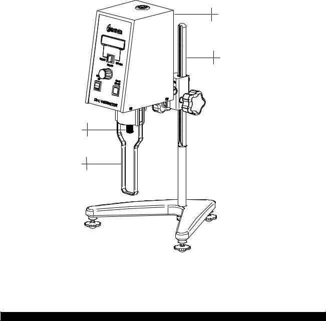
DV-E
Viscometer
Model A
Laboratory Stand
Shipping
Cap
Guard Leg
Figure I-1
Brookfield Engineering Labs., Inc. |
Page 6 |
Manual No. M98-350-J0912 |

I.2 Instrument Dimensions
11 47/64” [29.8 cm]
DV-E VISCOMETER
6”
4 5/64” 
 [15.3 cm] [10.4 cm]
B-20Y |
14 41/64” |
LV GUARD LEG |
[37.2 cm] |
ASSEMBLY |
|
|
7 13/32” |
|
[18.8 cm] |
1 7/16” |
|
[3.7 cm] |
|
10 7/8”
[27.6 cm]  VS-1Y LAB STAND BASE ASSEMBLY
Figure I-2
16 23/64” [41.5 cm]
Brookfield Engineering Labs., Inc. |
Page 7 |
Manual No. M98-350-J0912 |

I.3 Utilities
Input Voltage: |
115 VAC or 230 VAC |
|
||
Input Frequency: |
50/60 Hz |
|
||
Power Consumption: |
Less than 20 WATTS |
|
||
|
|
|
|
|
Power Cord Color Code: |
United States |
|
|
Outside United States |
Hot (live) |
Black |
Brown |
||
Neutral |
White |
Blue |
||
Ground (earth) |
Green |
Green/Yellow |
||
Input voltage can only be internally selected by a qualified technician from Brookfield or an authorized Brookfield dealer.
I.4 Specifications |
|
|
|
Speeds: |
0.3, 0.5, 0.6, 1.0, 1.5, 2.0, 2.5, 3.0, 4.0, 5.0, 6.0, 10, 12, 20, 30, 50, 60, 100 RPM |
||
Weight: |
Gross Weight |
20 lb |
9 kg |
|
Net Weight |
17 lb |
7.7 kg |
|
Carton Volume |
1.65 cu ft |
0.05 m3 |
|
Carton Dimension |
19 x 10 x 15 in |
48 x 25 x 38 cm |
Operating Environment: 0°C to 40°C Temperature Range (32°F to 104°F)
|
20% - 80% R.H.: non-condensing atmosphere |
Accuracy: |
±1.0% Full Scale Range in Use (See Appendix D for details) |
Reproducibility: |
0.2% of Full Scale Range |
Electrical Certifications:
Conforms to CE Standards:
BSEN 61326: Electrical equipment for measurement, control and laboratory use - EMC requirements
BSEN 61010-1: Safety requirements for electrical equipment, for measurement, control and laboratory use.
NOTICE TO CUSTOMERS:
This symbol indicates that this product is to be recycled at an appropriate collection center.
Users within the European Union:
Please contact your dealer or the local authorities in charge of waste management on how to dispose of this product properly. All Brookfield offices and our network of representatives and dealers can be found on our website: www.brookfieldengineering.com.
Users outside of the European Union:
Please dispose of this product according to your local laws.
Brookfield Engineering Labs., Inc. |
Page 8 |
Manual No. M98-350-J0912 |
I.5 Set-Up
Note: “IQOQPQ”, a guideline document for installation, operation and performancevalidationforyourDV-EViscometer,canbedownloaded from our website: www.brookfieldengineering.com.
1.To assemble the Model A Laboratory Stand, place the upright rod into the base (refer to assembly instructions in Appendix E).
2.Insert the mounting rod on the back of the DV-E Viscometer into the hole on the clamp assembly. (Refer to Appendix E).
3.The Viscometer must be leveled. The level is adjusted using the three leveling screws on the base. Adjust so that the bubble level on top of the DV-E is centered within the circle.
Note: Check level peroiodically during use.
4.Remove theViscometer shipping cap from the pivot cup. This cap is designed to protect the Viscometerspindlecouplingnutduringshipment. Do not attempt to operate the Viscometer with the shipping cap in place! Save this cap for future use.
5.Make sure that the power switch at the rear of the DV-E is in the OFF (0) position. Connect thepowercordtothesocketonthebackpaneloftheinstrumentandplugitintotheappropriate AC power line.
The AC input voltage and frequency must be within the appropriate range as shown on the name plate of the viscometer.
The DV-E must be earth grounded via its power mains cable plug/socket for electrical safety and to ensure against electronic failure!!
I.6 Safety Symbols and Precautions
Safety Symbols
The following explains safety symbols which may be found in this operating manual. Indicates hazardous voltages may be present.
Refer to the manual for specific warning or caution information to avoid personal injury or damage to the instrument.
Precautions
If this instrument is used in a manner not specified by the manufacturer, the protection provided by the instrument may be impaired.
This instrument is not intended for use in a potentially hazardous environment.
Brookfield Engineering Labs., Inc. |
Page 9 |
Manual No. M98-350-J0912 |
In case of emergency, turn off the instrument and then disconnect the electrical cord from the wall outlet.
The safety of any system, incorporating this instrument, is the responsibility of the assembler of the system.
The user should ensure that the substances placed under test do not release poisonous, toxic or flammable gases at the temperatures to which they are subjected to during the testing.
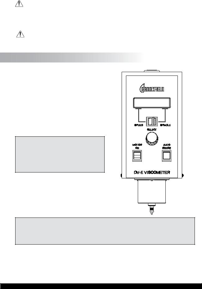
I.7 Instrument Controls
The following describes each switch’s function:
MOTOR ON
Turns the motor ON or OFF.
AUTO RANGE
Presentsthe maximum(100%torque)viscosity attainable using the selected spindle at the selected speed. This value is referred to as full scalerange. Theallowableerrorfortheviscosity measurement is ± 1% of full scale range.
Note: Pressing and holding the AUTO RANGE key during power on will enable the viscosity display to be read in either CGS (cP) or SI (mPa•s) units.
SPEED/SPINDLE SWITCH
Setstheviscometerineitherspeedselectorspindle select(seeTableC-1inAppendixC)mode. When set in the left position, the operator may select speed of rotation. When set in the right position, the operator may select spindle.
Note: This is a three (3) position switch. We recommend that the switch be set to the
Figure I-2
middlepositionwhenfinishedwithspindleorspeedadjustment. Thiswillprevent
an accidental change of parameters during a test.
SELECT KNOB
This knob is used to scroll through the available speed or spindle selections (see Table C-1 in AppendixC). Thisknobisactivewhentheswitchissettotheleft(speed)orright(spindle)position.
Rotate the knob clockwise to increase value and counter-clockwise to decrease value.
Brookfield Engineering Labs., Inc. |
Page 10 |
Manual No. M98-350-J0912 |
I.8 Cleaning
Make sure the instrument is in a decent working environment (dust-free, moderate temperature, low humidity, etc.).
Make sure the instrument is on a level surface.
Hands/fingers must be clean and free of residual sample. Not doing so may result in deposit build up on the upper part of the shaft and caue interference between the shaft and the pivot cup.
Be sure to remove the spindle from the instrument prior to cleaning. Note lefthand thread. Severe instrument damage may result if cleaned in place.
Instrument and Keypad: |
Clean with dry, non-abrasive cloth. Do not use solvents |
|
or cleaners. |
Immersed Components (spindles): |
Spindles are made of stainless steel. Clean with non- |
|
abrasiveclothandsolventappropriateforsamplematerial |
|
that is not aggressive to immersed components. |
When cleaning, do not apply excessive force which may result in bending spindles.
Brookfield Engineering Labs., Inc. |
Page 11 |
Manual No. M98-350-J0912 |

II. GETTING STARTED
II.1 Power Up
Turn the power switch (located on the rear panel) to the ON (I) position. This will result in the following screen display:
BROOKFIELD |
DV-E |
|
RV |
VISCOMETER |
|
|
|
|
Figure II-1
After a few seconds, the following screen appears:
BROOKFIELD DV-E
VERSION: 1.00
Figure II-2
After a short time, the display will clear and the default screen is displayed:
cP
10OFF % S02
Figure II-3
II.2 Spindle Selection
LVDV-E Viscometers are provided with a set of four spindles and a narrow guardleg; RVDV-E Viscometers come with a set ofsixspindlesanda“wider”guardleg;HADV-EandHBDV-E Viscometers come with a set of six spindles and no guardleg. (See Appendix F for more information on the guardleg.)
Thespindlesareattachedtotheviscometerbyscrewingthemto the male coupling nut (see Figure II-4). Note that the spindles and coupling have a left-hand thread. The lower shaft should be held in one hand (lifted slightly), and the spindle screwed to the left. The face of the spindle nut and the matching surface onthecouplingnutshaftshouldbesmoothandcleantoprevent eccentric rotation of the spindle. Spindles can be identified by the number on the side of the spindle coupling nut.
The DV-E musthaveaSpindleEntryCodenumbertocalculate viscosity values. The DV-E memory contains parameters for all standard Brookfield spindles and the two digit entry code for each spindle (the complete list of spindle entry codes may be found in Appendix C).
Note: The DV-E will display the Spindle Entry Code which was in use when the power was turned off.
Figure II-4
Brookfield Engineering Labs., Inc. |
Page 12 |
Manual No. M98-350-J0912 |
 Loading...