


R-S Coaxial Cylinder Rheometer
BROOKFIELD R/S+ RHEOMETER
Operating Instructions
Manual No. M08-219-B1211
(for serial numbers beginning with “304”)
with oces in:
BROOKFIELD ENGINEERING LABORATORIES, INC.
11 Commerce Boulevard, Middleboro, MA 02346 USA
TEL508-946-6200
FAX508-946-6262
Boston • Chicago • London • Stuttgart • Guangzhou
or
800-628-8139
I
NTERNET
http://www
SPECIALISTS IN THE
MEASUREMENT AND
CONTROL OF VISCOSITY
(USAexcluding
.brookeldengineering.com
MA)
Brookfi eld Engineering Labs., Inc. Page 1 Manual No. M08-219-B1211


Table of Contents
I. General Description ....................................................................................................... 7
I.1 Use of the Rheometer ...................................................................................................7
I.2 Measuring Principle .......................................................................................................7
II. System Confi guration ............................................................................................... 8
II.1 R/S+ Rheometer ..........................................................................................................8
II.2 Measuring Geometries (Spindles or Bobs with Sample Cups) .................................... 10
II.3 Computer System Requirements .................................................................................10
III. Instrument Installation .............................................................................................. 11
III.1 Mounting the Stand .....................................................................................................11
III.2 Electrical Connections ..................................................................................................12
III.2.1 Temperature Sensor PT100 ............................................................................... 12
III.2.2 AC Adapter .........................................................................................................13
III.2.3 Printer Connection .............................................................................................13
III.3 Connecting Temperature Controlled Measuring Devices ..........................................14
III.2.4 Computer Connection ........................................................................................14
III.3.1 Connecting the Water Jacket ............................................................................. 14
III.3.2 Connecting the Optional Cone/Plate Attachment ...............................................16
III.3.3 Connecting the KE Cooling Device .................................................................... 17
IV. Environment, Handling, Cleaning and Maintenance ............................................. 19
IV.1 Operating Environment and Storage ...........................................................................19
IV.2 Handling .......................................................................................................................19
IV.3 Cleaning .......................................................................................................................19
IV.4 Maintenance ................................................................................................................ 20
V. Measuring Systems .................................................................................................. 21
V.1 Measuring Directly in the Sample Container ................................................................. 21
V.2 Measurement by Filling the Sample Cup .......................................................................22
V.3 Measurement with Water Jacket Assembly ...................................................................22
V.4 Measurement with Cone/Plate or Plate/Plate Measuring Systems ............................... 23
VI. Operation and Menu System ................................................................................... 25
VI.1 Keyboard ..................................................................................................................... 26
VI.2 Menu System of R/S+ Rheometer ...............................................................................28
VI.3 Selecting from Lists ..................................................................................................... 29
VI.4 Input of Numerical Values and Alphanumeric Texts ..................................................... 30
VI.5 Menu Entries (MAIN Menu) ......................................................................................... 31
VI.5.1 MAIN Menu → Run Single ................................................................................ 32
VI.5.2 MAIN Menu
VI.5.3 MAIN Menu → Run Program ..............................................................................34
VI.5.4 MAIN Menu → Remote .......................................................................................36
VI.5.5 MAIN Menu → Utilities .......................................................................................37
VI.5.6 MAIN Menu → Confi guration .............................................................................. 37
VI.6 Menu Entries in the Utilities Menu ............................................................................... 37
VI.6.1 Utilities → Zero Calibration .................................................................................38
→ Single Measurement .................................................................32

VI.6.2 Utilities → Edit Program .....................................................................................38
VI.6.3 Utilities → Print Programs ..................................................................................42
VI.6.4 Utilities → Measuring Systems ...........................................................................42
VI.6.5 Utilities → Print Memory .....................................................................................43
VI.6.6 Utilities → Clear Memory ....................................................................................44
VI.6.7 Utilities → Measure Temperature ....................................................................... 44
VI.7 Menu Entries of the Confi guration Menu ..................................................................... 45
VI.7.1 Confi guration → Set Output Mode .....................................................................45
VI.7.2 Confi guration → Set MeasCount Mode .............................................................. 46
VI.7.3 Confi guration → Reset MeasCount ..................................................................... 46
VI.7.4 Confi guration → Set Time/Date ..........................................................................46
VI.7.5 Confi guration → Set RS-232 Parameters ..........................................................47
VI.7.6 Confi guration → Language .................................................................................49
VI.7.7 Confi guration → Service .....................................................................................49
VI.8 Serial Data Transfer via the RS-232 Interface .............................................................49
VII. Measurements ............................................................................................................ 51
VII.1 Measuring in Manual Mode ......................................................................................... 51
VII.2 Measuring with Water Jacket ...................................................................................... 51
VII.3 Measurement with Cone/Plate Attachment ................................................................. 51
VII.4 Measurement in Remote Mode ................................................................................... 52
VIII. Technical Data ........................................................................................................... 53
Appendix A ........................................................................................................................ 55
A.1 Data Sheets of Standard Measuring Systems ..............................................................55
A.2 Error Messages ............................................................................................................. 57
A.3 Pin Assignment of the Serial Data Cable ......................................................................60
A.4 Requirements to the AC Power Connecting Cables .....................................................60
Appendix B: Calibration Check Procedure .................................................................... 62
B.1 Using Rheo 3000 ..........................................................................................................62
B.2 Stand-alone Mode ......................................................................................................... 63
Appendix C: RS4SSTB Rheometers for Measuring in Brabender Units (BU) ...........64
C.1 Adjusting the BU Factor ................................................................................................65
C.2 Test Program ................................................................................................................. 65
Appendix D: R/S-SST+ - Soft Solid Tester ..................................................................... 66
D.1 Operating the R/S-SST+ Soft Solids Tester .................................................................. 66
D.1.1 Running a Sample Using Software Control .......................................................66
D.1.2 Soft Solids Analysis Functions ........................................................................... 66
D.1.3 Running a Sample in Stand-Alone mode. ..........................................................67
D.1.4 Editing and Running Programs .......................................................................... 68
D.2 Getting Started in Soft Solids Testing ...........................................................................68
D.2.1 The Constant Rate Test .....................................................................................68
D.2.2 The Creep Test ................................................................................................... 69
D.3 A Few Tips To Get You Started .....................................................................................70
D.3.1 Vane selection ....................................................................................................71
D.3.2 Container Dimensions ........................................................................................71

D.3.3 Setting Up Vanes In Measuring System Editor .................................................. 71
D.4 Vane Constants For The Soft Solids Tester .................................................................72
D.4.1 Stress Constant: τ
D.4.2 Strain/Rate Constant: K-Gamma .......................................................................72
....................................................................................... 72
prom.
Appendix E: R/S Portable Rheometer ...........................................................................74
E.1 Technical Specifi cations ...............................................................................................74
E.2 Electrical Connections .................................................................................................76
E.3 Measurement Range ...................................................................................................77
E.3.1 Data Sheets of Standard Measuring Systems ...................................................77
E.4 R/S Portable Components ...........................................................................................78
E.5 Operation Under Battery Power ...................................................................................79
Appendix F: Online Help and Other Resources ...........................................................80
Appendix G: Warranty and Repair Service .................................................................... 81


I. General Description
This section has general information about the instrument and operating principles.
I.1 Use of the Rheometer
The R/S+ Rheometer will measure viscosity of Newtonian and Non-Newtonian materials in
controlled shear rate (CSR) or controlled shear stress (CSS) modes. The instrument can measure
simple viscosity at a given speed or shear rate, or measure fl ow properties with a fl ow curve at
shear rates up to ~1,200 sec-1.
In controlled stress mode, the instrument can do a direct yield test (stress ramp) and indicate
elasticity with creep/recovery tests.
I.2 Measuring Principle
The R/S+ Rheometer is a rotational, controlled shear stress instrument which can be operated in
controlled shear rate mode.
Concentric cylinders, measuring cones and plates are available as a measuring system. The
measuring sample is positioned in a measuring gap between the stationary measuring cup and
the rotating measuring bob (Searle-principle), respectively between the rotating cone or plate and
the stationary lower plate (cone/plate, cone/cone measuring system).
The measuring drive developed for this instrument operates with a high precision, dynamic drive
system with optical encoder for absolute position measurement of spindle geometry.
The R/S+ measuring drive can operate at a pre-set of speed (shear rate) or pre-set of torque (shear
stress). Measurements may be made in manual mode (without PC) or under PC control with Rheo
3000 software. Note that the creep measurements require a computer system with Rheo 3000
software.
Both CSR and CSS measurements can be carried out manually (without PC support) or with a
computer system and Rheo 3000 software.
Brookfi eld Engineering Labs., Inc. Page 7 Manual No. M08-219-B1211

II. System Confi guration
The R/S+ Rheometer system consists of:
•
Rheometer head containing electronic unit and measuring drive integrated in one
housing
•
Lab Stand with removable catchment table
•
AC Adapter
Available Accessories:
•
Coaxial cylinder measuring system (see Appendix A)*
•
Temperature measuring sensor Pt100*
•
Water jacket assembly
•
Bath/Circulator
•
Rheo 3000 software for control of R/S+ by PC
•
Vane spindles
•
BU Spindles
•
Cone/Plate and Plate/Plate Assembly
*
The accessories in bold print are necessary for a minimal confi guration. See Figure II-1
for illustration of the R/S+ Rheometer System Components.
Available Services:
•
Startup Assistance
•
Instrument Training
•
Rheo 3000 Software Training
II.1 R/S+ Rheometer
Instrument features include:
•
Digital control of rotational speed and torque
•
Automatic adjustment of control parameters during measurement
•
Direct indication of measured and calculated values of speed/shear rate, torque/shear
stress, viscosity, temperature, and time
Data storage (measured values)
•
Data output to a printer (parallel)
•
User support with LCD and keypad
•
Built-in system interface with serial standard interface (RS232) for connection to a
•
computer or other serial data-logger
Printing and serial data-transmission during the test
•
The R/S+ Rheometer can either be operated manually using the keypad on the front panel or it
can be operated under computer control. The R/S+ Rheometer is supplied with a direct current
drive by the AC Adapter.
Brookfi eld Engineering Labs., Inc. Page 8 Manual No. M08-219-B1211
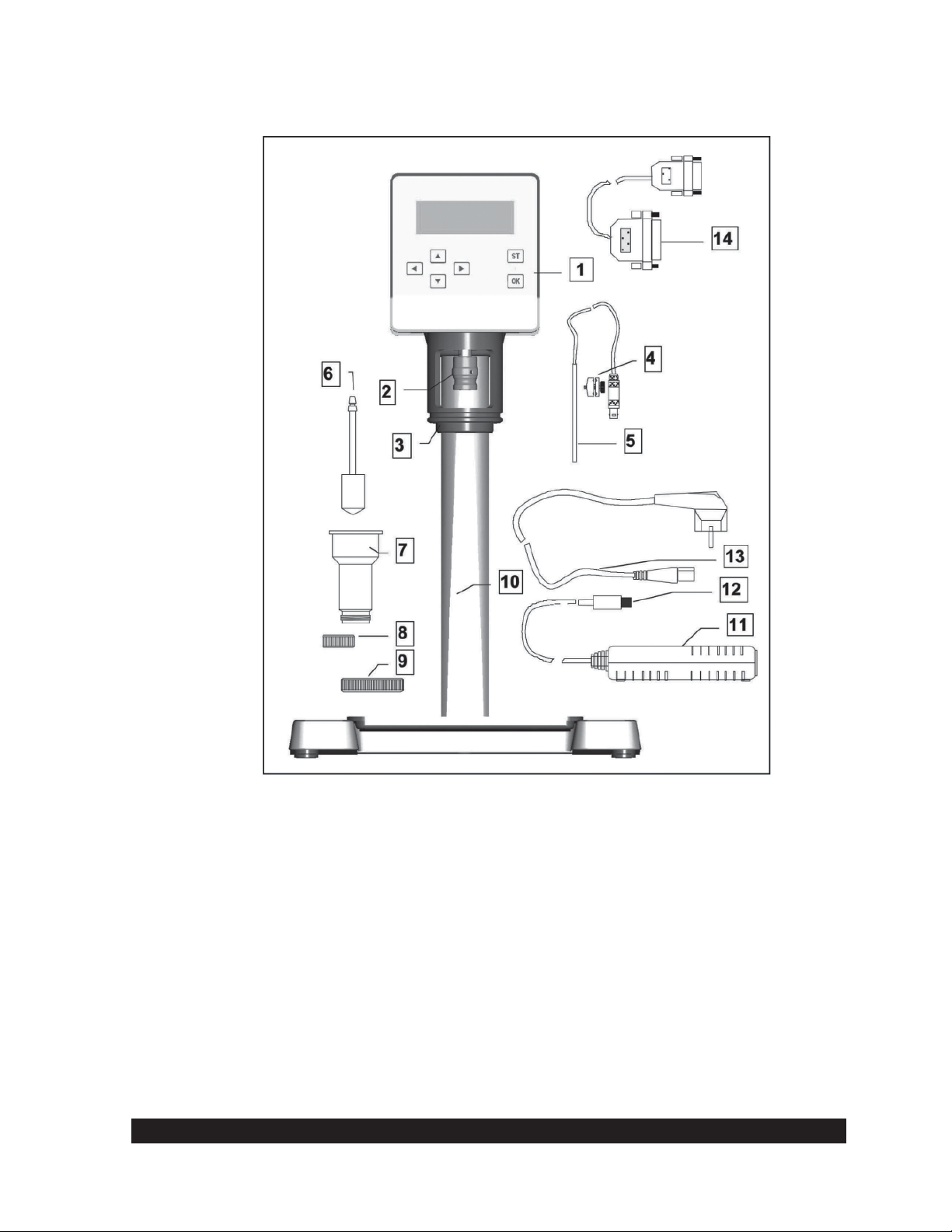
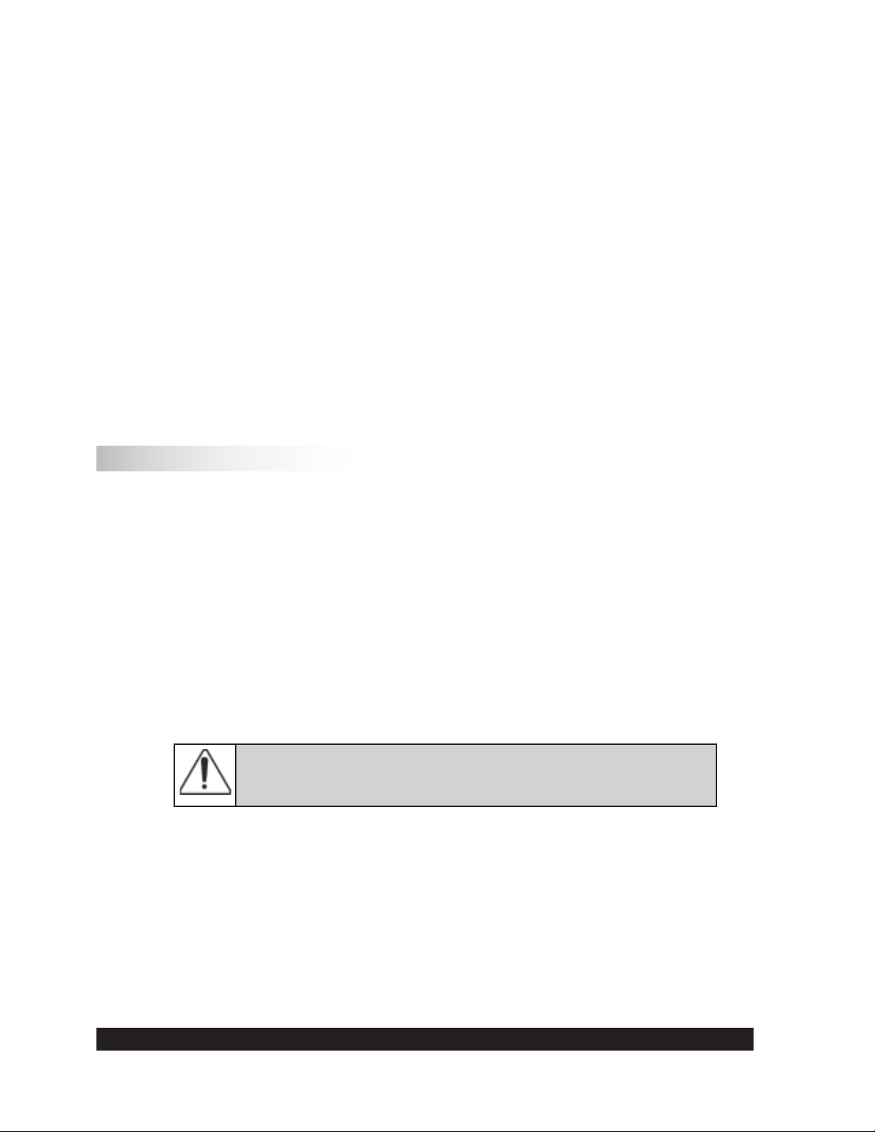
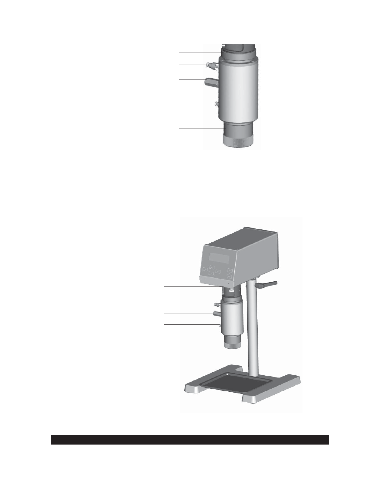
R/S+ Rheometer
1 R/S+ Rheometer Head
2 Measuring Bob Coupling
3 Mounting Flange
4 Pt100 Clamp Fixture (accessory)
5 Pt100 (temperature probe accessory)
6 Standard Measuring Bob (accessory)
7 Standard Measuring Cup (accessory)
8 Measuring Cup Bottom or Thread Protection (accessory)
9 Measuring Cup Screw Fitting
10 Lab Stand
11 AC Adapter
12 Direct Current Plug (to Rheometer head)
13 AC Power Cable
14 RS232C Cable (accessory)
Fig. II-1: Confi guration of the R/S+ Rheometer
Brookfi eld Engineering Labs., Inc. Page 9 Manual No. M08-219-B1211

II.2 Measuring Geometries (Spindles or Bobs with Sample Cups)
Measuring devices are not included in the base instrument price and must be ordered
separately.
Measuring devices that can be used with the R/S+ include:
• Coaxial geometry measuring systems (see Appendix A) with and without built-in temperature
sensor Pt100
• Water Jacket Assembly for use with the coaxial cylinder measuring system in temperature
range -10°C to +180°C
• Vane spindles (see Appendix D) for measuring soft solids
• BU Spindle (see Appendix C) for measuring joint compound in Brabender units
• Cone/Plate Assembly for measuring small sample volumes <1mL
II.3 Computer System Requirements
The computer system control of the R/S+ is optional and provides automatic measuring, data plots,
printing (full reports or data plots) as well as analysis of results and quality control charts.
The recommended computer system has the following minimal system requirements:
- CPU / 1 GHz
- 512 MB RAM (main memory)
- 500 MB free hard disk capacity
Compatible operating system includes:
- Microsoft Windows 2000™, Windows XP™, Windows 7™ or Vista™
- mouse and keyboard
- VGA graphic card and monitor
- 1 free serial interface
Brookfi eld Engineering Labs., Inc. Page 10 Manual No. M08-219-B1211
III. Instrument Installation
III.1 Mounting the Stand
The stand consists of:
the stand base plate
•
the stand column with rheometer
•
A 5 mm Hex wrench and bolt DIN 912 M8 x 40 are supplied for mounting.
The stand column is connected to the stand base plate with a bolt. The proper orientation of the
column is set with a pin in the bottom of the column which fi ts into a hole on the stand base.
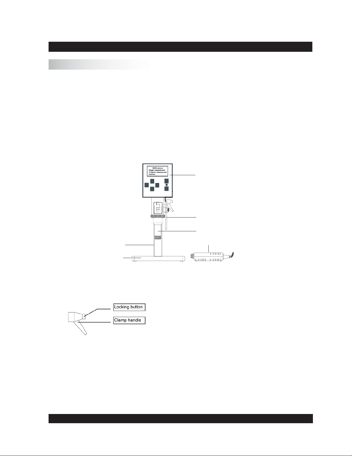
Rheometer
Stand
Base
Fig. III-1.: Rheometer R/S+ (minimum confi guration)
Hints for height adjustment of the stand:
To change the height adjustment of the stand, you must release the
clamp handle and move the stand to the desired height.
Caution: Hold the rheometer as you release the clamp handle!
You can press the locking button to change the clamp handle position without screwing/unscrewing the thread. After adjustment of the
height screw, tighten clamp handle thread.
Fig. III-2.: Stand Height Adjustment Hints
Temperature Sensor Pt100
Coaxial Cylinder System
AC Adapter
Brookfi eld Engineering Labs., Inc. Page 11 Manual No. M08-219-B1211

III.2 Electrical Connections
Connections for the electrical components of the R/S+ Rheometer are located on the back of the
instrument head.
Parallel Printer Connection
RS232C Computer Connection
Socket for Pt100 Temperature Probe
Socket for AC Adapter
ON/OFF Switch
Fig. III-3: Operating and connecting elements at the back side of the measuring head
All cables to and from the R/S+ Rheometer may be connected or
disconnected only when the instrument is turned off!
III.2.1 Temperature Sensor PT100
The connecting cable for the temperature sensor Pt100 (100 ohm DIN alpha RTD) is inserted into
the socket labeled “Pt100” at the back of the rheometer head.
If you use standard cylindrical measuring cups (CC8, CC14 etc.), put the Pt100 into the mounting
clamp fi xture and align it parallel to the measuring system by attaching it to the mounting fl ange
of the rheometer.
Fig. III-4: Pt100 connection and mounting
Brookfi eld Engineering Labs., Inc. Page 12 Manual No. M08-219-B1211
Insert the plug for the Pt100 connector in the back of the rheometer head.
Since viscosity is a function of temperature, the temperature should be preferably measured in the
test fl uid. For this purpose, the standard measuring systems 8 mm to 40 mm DIN can be equipped
with a Pt100 in the measuring cup bottom when the water jacket is used. If you use a measuring
system with built-in Pt100, this is where you will insert the cable VK-Pt/RC.
III.2.2 AC Adapter
Do not use a power supply other than the AC adapter delivered by Brookfi eld for the R/S+
Rheometer.
Connect the AC adapter using a grounded plug to avoid electric
shock or damage to the system components!
Connecting the AC adapter:
Turn the R/S+ Rheometer off with the “POWER” switch at the back side of the
instrument.
Connect the RS+ power cord into the AC adapter.
Insert the socket of the DC cable into the “DC” connector port at the back side of the
instrument.
Plug the power cable into a grounded AC power socket.
Turn the R/S+ Rheometer on.
-
Do not leave the power supply plugged into the AC power socket when the cable to the
rheometer is un-plugged!
Before disconnecting the rheometer from the AC supply, be sure that the instrument is
switched off.
III.2.3 Printer Connection
A printer can be connected directly to the interface connector of the rheometer when measuring
without PC control. You must preset “Printer” as the output device to print the measuring values
during measurement (see Section VI). The printer should have a parallel printer interface. USB
printers are not supported.
Turn off the rheometer with the AC power switch at the back of the R/S+.
Insert the printer connecting cable into the “PRINTER” port on back of the
instrument.
Turn the R/S+ Rheometer on.
-
A standard printer cable can be used as a printer connecting cable. This cable is supplied with the
printer in most cases. To print data values from the R/S+ Rheometer, any (parallel) printer which
can operate in ASCII character mode may be used.
Brookfi eld Engineering Labs., Inc. Page 13 Manual No. M08-219-B1211
III.2.4 Computer Connection
If the R/S+ Rheometer has to be used in “REMOTE” mode with a PC (Rheo 3000 program
package) or with serial data-terminal for data logging, the RS232C cable needs to be connected
to the 25 pin port labeled “RS232” on the back of the instrument.
Turn the R/S+ Rheometer off with the “POWER” switch at the back of the
•
instrument.
Turn the computer system off.
•
Connect the rheometer data cable to the 25 pin port labelled “ RS232” on the back of
•
the R/S+ Rheometer.
Connect the Peltier data cable to the port labelled “ RS232/Peltier” on the back of the
•
rheometer head.
Turn the R/S+ Rheometer and your computer system on again.
•
You must use the computer cable supplied by Brookfi eld - other cables will not work!
III.3 Connecting Temperature Controlled Measuring Devices
Water Jacket Assembly: for use with the cylinder measuring system, in the temperature
•
range of -10°C to +90°C (liquid’s temperature control).
Cooling Device KE: expands the temperature range from -20°C to +180° in conjunction
•
with the FTKY3 temperature control device or CONE/PLATE ATTACHMENT.
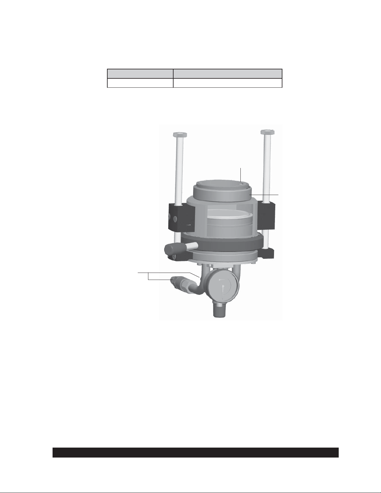
III.3.1 Connecting the Water Jacket
The Water Jacket FTKY3 is an optional accessory for use with the coaxial cylinder measuring
system in the temperature range -10°C to +90°C.
The water jacket should be used only in the temperature range
-10°C to +90°C unless the KE cooling device is installed, in which
case, the temperature range is -20°C to +180°C!
Brookfi eld Engineering Labs., Inc. Page 14 Manual No. M08-219-B1211
Thread Joint for Connection of
Measuring Cup to Mounting Flange
Hose Connection of Flow Output
Temperature Sensor Pt100
Hose Connection of Flow Input
Measuring Cup Bottom
Fig. III-5: Water Jacket Assembly
Mounting the Water Jacket Assembly:
When using the KE cooling device, mount the cooling device fi rst (see Section
•
III.3.3).
Attach the jacket on the mounting fl ange from below and tighten the thread.
•
Connect the tubes from the water bath to the jacket.
•
Connect the jacket’s built-in Pt100 cable to the R/S+ Rheometer.
•
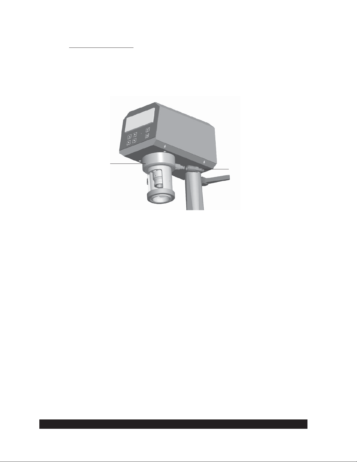
Cooling Device KE-FTK/RC30
Tube Connector
Temperature Sensor Pt100
Tube Connector
Water Jacket
Fig. III-6: Operation with the Water Jacket Assembly FTKY3 and Cooling Device KE
Brookfi eld Engineering Labs., Inc. Page 15 Manual No. M08-219-B1211

Bath/Circulator Connection to the Water Jacket
The tubes are used to connect the bath to the R/S+ water jacket.
The tubes are connected to the quick fi tting couplings on the jacket assembly. The coupling has a
female part which is put into the tubing, and a male part built into the jacket assembly. To connect
the two, pull back on the female section slide ring and put the connector onto the jacket (male)
connector, releasing the slide ring.
Water jacket without cooling device KE is only used in the
temperature range -10°C to +90°C!
The jacket FTKY3 can be used in the temperature range -20°C to +180°C when used with the
optional KE cooler (for tap water cooling of the rheometer bearings).
The following working fl uids are usually used in the temperature bath:
-10°C to +90°C Water - Glycol Mixture
-20°C to +180°C Bath Oil
Suitable bath fl uids can be ordered from BROOKFIELD.
III.3.2 Connecting the Optional Cone/Plate Attachment
Turn off the R/S+.
•
When using the KE cooling device, mount the cooling device fi rst (see Section
•
III.3.3)
Set the “CONE/PLATE ATTACHMENT” from below the mounting fl ange and tighten
•
the thread. Before tightening, check that the guide pin of the measuring device (see Fig.
III-7) is in the slot of the R/S+ mounting fl ange!
Connect the bath tubes to the “CONE/PLATE ATTACHMENT”.
•
Connect the Cone/Plate and temperature probe cable to the R/S+.
•
For mounting the cone/plate or plate/plate measuring systems to the measuring device
•
refer to Section V.
Bath/Circulator Connection to the Cone/Plate Attachment
The hoses are connected to the quick fi tting couplings on the cone/plate assembly. The coupling
has a female part which is put into the tubing, and a male part built into the jacket assembly. To
connect the two, pull back on the female section slide ring and put the connector onto the jacket
(male) connector, releasing the slide ring.
Brookfi eld Engineering Labs., Inc. Page 16 Manual No. M08-219-B1211
The following working fl uids are usually used in the temperature bath:
-10°C to +90°C Water - Glycol Mixture
-20°C to +180°C Bath Oil
Suitable bath fl uids can be ordered from BROOKFIELD.
Guide Pin
Screw Connection for
Mounting Flange
Bath Tubing Connectors
Fig. III-7: CONE/PLATE ATTACHMENT for cone/plate and plate/plate systems
III.3.3 Connecting the KE Cooling Device
The optional cooling device KE COOLING ATTACHMENT must be used where the test
temperature is below -10°C or above 90°C. When using the KE COOLING ATTACHMENT,
the temperature range is expanded from -20°C to +180°C.
Brookfi eld Engineering Labs., Inc. Page 17 Manual No. M08-219-B1211
Attachment Procedure
Turn off the R/S+.
•
Lift the KE COOLING ATTACHMENT to the R/S+ Rheometer from below and tighten
•
the thread.
Connect the tubes of the cooling line to the KE COOLING ATTACHMENT (see Figure
•
III.8).
Cooling Device KE
Fig. III-8: Cooling Device KE
Hose Connection
• The tubes for the KE Cooling Device are connected with quick connect couplings.
Brookfi eld Engineering Labs., Inc. Page 18 Manual No. M08-219-B1211
IV. Environment, Handling, Cleaning and Maintenance
IV.1 Operating Environment and Storage
Find a convenient work place for the installation of the R/S+ Rheometer. There should be enough
room to place the rheometer, the measuring systems, the measuring substances and the peripheral
devices (e.g. printer, computer and bath/circulator). You need a grounded AC plug to operate
the R/S+ Rheometer and additional plugs for the connection of each peripheral device (i.e. Bath,
Peltier). Your operating environment and the place where you store the R/S+ Rheometer should
not be extremely hot, extremely cold or extremely moist. Places with large temperature and air
humidity variations should be avoided. Be sure that the R/S+ Rheometer is not exposed to the
following:
heavy dirt or dust
•
direct sun
•
•
objects that emit heat (e.g. heating radiators)
•
objects with a strong electromagnetic fi eld (e.g. loudspeakers, motors etc.)
•
liquids or corrosive chemicals
IV.2 Handling
The R/S+ Rheometer is designed to endure light bumps or vibration. Avoid dropping it or exposing
it to heavy shock!
Never lift your RS+ Rheometer at the measuring bob coupling or with
the measuring bob attached to the instrument.
Always disconnect the bob at the bob coupling before removing the
sample cup!!!!
The rheometer motor will automatically turn off if the maximum torque (50 mNm) is exceeded.
IV.3 Cleaning
The paint coat of the R/S+ Rheometer resists most usual solvents and weak acids. Use a dry, clean,
soft and nap-free piece of cloth to clean the housing. Use neutral detergent liquids, if necessary.
Do not use chemical products such as strong solvents or strong acids to
clean the housing, especially the keyboard.
Brookfi eld Engineering Labs., Inc. Page 19 Manual No. M08-219-B1211
IV.4 Maintenance
The R/S+ Rheometer system is designed for long-term operation. Should the instrument require
repair, contact Brookfi eld or your Brookfi eld dealer.
Only authorized service personnel may work on the control
electronics, all accessories, the measuring drive, as well as the AC
Adapter and all electric circuits and connections!
Measurement accuracy can be checked by the user at any time. We recommend that the
measurements be done with Brookfi eld viscosity standard fl uids (mineral oils) as recommended
for each individual spindle geometry.
You must:
Use temperature control (i.e. water jacket and circulating bath)
•
Select the appropriate measuring system
•
Carry out measurements at the following pre-set M (‰ torque): 250‰, 500‰ and 750‰
•
Read viscosities from the display
•
In case of instrument failure (or severe deviation from the preset value), contact Brookfi eld or
your Brookfi eld Dealer.
Brookfi eld Engineering Labs., Inc. Page 20 Manual No. M08-219-B1211
V. Measuring Systems
V.1 Measuring Directly in the Sample Container
You may immerse the measurement system directly into a container of sample by removing the
cap on the bottom of the immersion cups.
When using the double gap bob measuring system, do not damage the “O” ring which forms the
seal between the inner and outer parts of the sample cup. To clean, the inner section is removed
by unscrewing the (stainless steel) ring at the bottom and then GENTLY push the inner section
out through the bottom of the outer section. Take care not to damage or stretch the O-ring seal
during removal! Insert the inner part again and screw the ring back on.
General steps for direct immersion of the measuring system into the bath:
Lift the coupling sleeve of the measuring bob coupling (the ring is visible).
•
Insert the measuring bob into the measuring bob coupling.
•
Lower the coupling sleeve (the ring is covered).
•
Fasten the measuring cup at the measuring cup mounting fl ange with the measuring cup
•
ring.
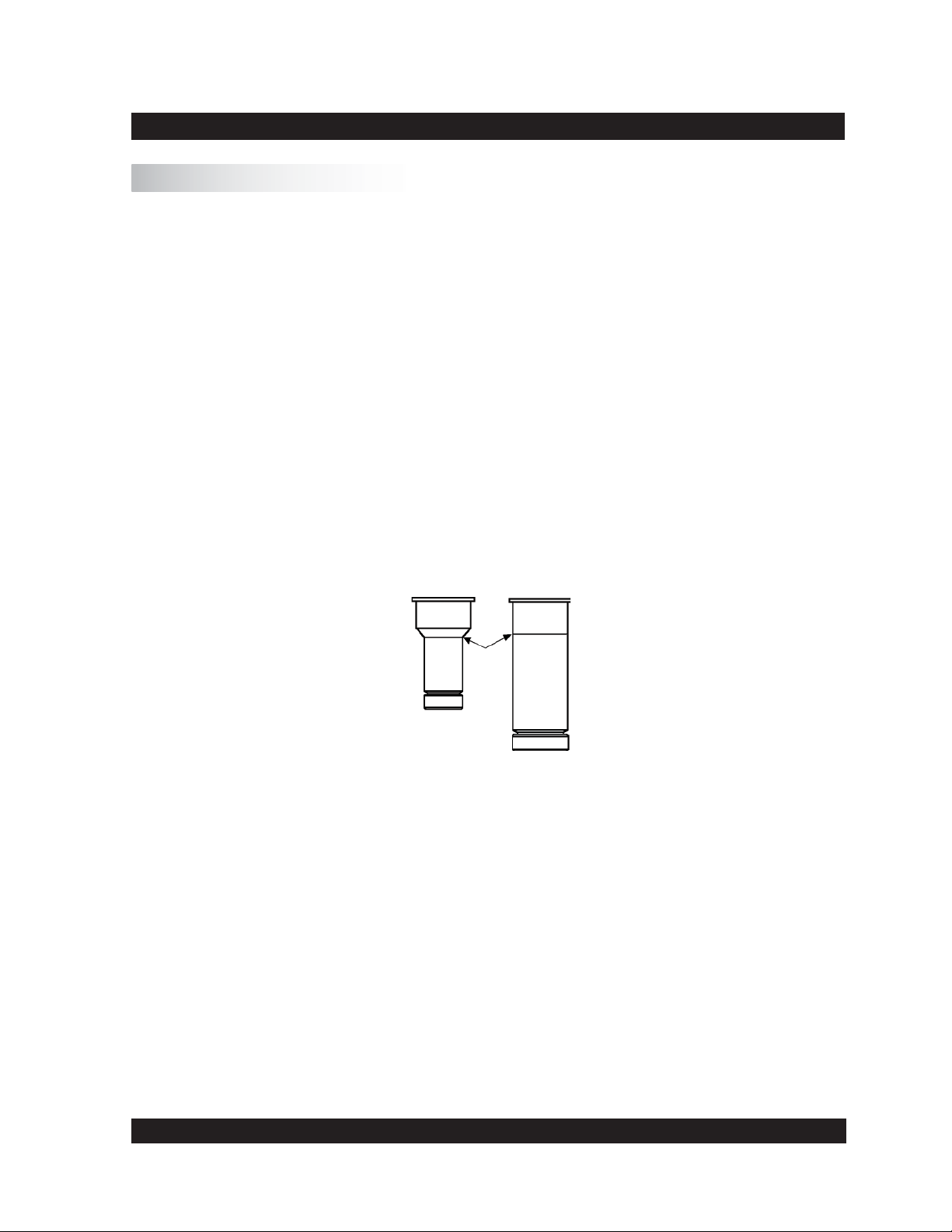
Immerse the measuring cup into the substance up to the ring mark or up to the point where
•
the diameter of the measuring cup increases.
Fig. V-1: Depth of immersion
Do not get sample in or onto the measuring bob coupling.
After making your viscosity measurement, unscrew the measuring cup ring and remove the
measuring cup. Open the measuring bob coupling, and remove the measuring bob.
Clean the measuring cup and measuring bob carefully. Do not use abrasive cleaning tools, and
always prevent scratches! Store measuring bobs on a soft pad.
Brookfi eld Engineering Labs., Inc. Page 21 Manual No. M08-219-B1211
V.2 Measurement by Filling the Sample Cup
Fill the measuring cup with your material (see Appendix A.1 for sample volume). Avoid air
bubbles when fi lling the sample as they can affect the repeatability of the test!
Place the measuring bob into the measuring cup. Lift the coupling sleeve (the ring is visible).
Insert the complete measuring system into the measuring cup mounting fl ange from below and
screw on using the measuring cup ring. Now, insert the measuring bob shaft completely into the
measuring bob coupling and lower the coupling sleeve (the ring is covered).
If you want to measure with temperature control, the bath/circulator must be pre-set at the desired
temperature and you should wait until bath liquid and sample are at test temperature.
To remove the measuring system after the viscosity measurement has been completed, fi rst open
the measuring bob coupling and then unscrew the measuring cup thread.
When unscrewing the measuring cup, you must hold the measuring
system tightly with one hand to avoid dropping the cup and bob!
Clean the measuring cup and measuring bob carefully with a soft cloth to avoid scratches!
V.3 Measurement with Water Jacket Assembly
Install the FTKY3 jacket by removing the measuring cup ring on the rheometer (see Figure III.5).
Attach the jacket to the rheometer using the ring built onto the top of the jacket.
Connect the tubing from the bath (the bath outlet to the bottom tubing connection of the jacket;
the bath inlet to the top of the connection on the water bath) to the jacket , and connect the Pt100
on the jacket to the Pt100 socket on the back of the rheometer.
When using disposable measuring systems, insert the disposable measuring cup into the receptacle.
Fill the measuring cup with the sample. (See Appendix A.1 for sample volumes).
Avoid air bubbles when fi lling the sample as they can affect the repeatability of the test!
Place the measuring bob in the measuring cup. Lift the coupling sleeve (ring is visible). Insert the
cup and bob into the jacket from below and screw on using the measuring cup ring. Insert the bob
shaft into the measuring bob coupling and lower the coupling sleeve (ring is covered).
Set the water bath to test temperature. After the bath is at the test temperature, wait 15 minutes
to ensure that the sample, cup and bob are at test temperature.
Brookfi eld Engineering Labs., Inc. Page 22 Manual No. M08-219-B1211
To remove the measuring system after the measurement, fi rst open the coupling sleeve for the
bob, then unscrew the measuring cup ring.
When unscrewing the measuring cup, you must hold the measuring
system tightly with one hand to avoid dropping the cup and bob!
When using disposable measuring cups, eject the disposable measuring cup with the pusher.
V.4 Measurement with Cone/Plate or Plate/Plate Measuring Systems
Installing and adjusting the measuring cone or measuring plate
When installing a cone or plate, the lower plate must be in the down position (move the locking
lever to the left and gently pull the lower plate down).
When releasing the bayonet lock, the measuring device has to be held
tightly from below.
Loosen the set screw on the cone or plate and push the cone or plate bottom up, setting the shaft
length to the minimum.
Lift the coupling sleeve (red ring mark should be visible). Insert the cone or plate from below into
the measuring coupling. Lower the coupling sleeve (ring is covered) to attach the spindle.
Turn the adjusting screw on the plate down to the lowest position. Raise the plate to the top
position and secure it with the bayonet lock (position “closed”).
The actual distance between spindle and plate has to be adjusted to approximately 1 mm by
turning the adjusting screw up. Set the screw mark to “0” with approximately 1 mm between
cone and plate.
The dial indicator should also be set to mark “0” for distance control. Unlock the spindle shaft
to bring the spindle onto the plate, and tighten the cone set screw to fi x the shaft.
The plate is now adjusted to 50 μm. The adjustment ring lowers the plate down when turned
clockwise (looking down onto the adapter), and raises it up by turning the ring counter-clockwise.
Lower the plate to 0.5 mm by turning the adjustment ring clockwise for one complete revolution.
Now raise the plate, but not all the way back to the zero position; stop at the “5” mark in the ring
which sets the gap to 50 μm.
Brookfi eld Engineering Labs., Inc. Page 23 Manual No. M08-219-B1211

Measurement
Open the bayonet lock and lower the plane-table. Apply the sample to be tested. Lift up the planetable and fi x the bayonet lock. Now, the measurement can start.
Remove excess sample from around the cone or plate before starting the
measurement.
If temperature control is required, a bath/circulator must be connected. The bath must be set at
the desired temperature, and you should wait until the bath and cone/plate accessory have reached
test temperature.
Brookfi eld Engineering Labs., Inc. Page 24 Manual No. M08-219-B1211

VI. Operation and Menu System
The following section summarizes the operation and the menu system of the R/S+ Rheometer for
both manual and PC-controlled measurement.
Menu prompts for the R/S+ Rheometer in stand-alone mode are available in the following
languages:
English
•
German
•
The language is selected via the menu level Confi guration→Language (if English is active)
or Konfi guration→Sprache (if German is active). For more details on language selection, see
Section VI.7.6.
After applying power to the R/S+ Rheometer, the LCD displays the following information for
a few seconds:
name of the rheometer
•
software version of the fi rmware installed in the instrument
•
serial number of the instrument
•
date and time
•
Example:
R/S+ Rheometer
Ver.: 9.00 #xxxxxx
27.10.11 15.12
©Brookfi eld Engineering
About fi ve seconds later, the instrument checks the voltage of the power supply. The displayed
voltage should be in the range of 14.9 to 16V. If the voltage is outside this range, contact Brookfi eld
or your local Brookfi eld dealer.
Example:
Voltage Check:
VCC:15.25 V
This message is displayed for about 3 seconds and then the MAIN menu is displayed. A brief
summary, in Section VI.4, of the rheometer keyboard and the corresponding rheometer functions
may be helpful before you get to the complete description of the menu.
Brookfi eld Engineering Labs., Inc. Page 25 Manual No. M08-219-B1211
 Loading...