


 Loading...
BROOKFIELD LFRA
TEXTURE ANALYZER
Operating Instructions
Manual No. M/05-370-A1205
SPECIALISTS IN THE
MEASUREMENT AND
CONTROLOF VISCOSITY
BROOKFIELD ENGINEERING LABORATORIES, INC. 11 Commerce Boulevard, Middleboro, MA 02346-1031 USA
TEL 508-946-6200 or 800-628-8139 (USA only)
FAX 508-946-6262 INTERNET www.brookfieldengineering.com
|
|
|
|
Brookfield Engineering Labs., Inc. |
Page |
1 |
Manual No. M/05-370-A1205 |
|
|
|
|

|
TABLE OF CONTENTS |
|
I. INTRODUCTION ................................................................................................................................. |
3 |
|
I.1 |
Components ................................................................................................................ |
3 |
I.2 |
Utilities ....................................................................................................................... |
4 |
I.3 |
Units ........................................................................................................................... |
4 |
I.4 |
Specifications ............................................................................................................. |
4 |
I.5 |
Installation .................................................................................................................. |
5 |
I.6 |
Safety Symbols and Precautions ................................................................................ |
6 |
I.7 |
Key Functions ............................................................................................................ |
7 |
I.8 |
Cleaning ..................................................................................................................... |
7 |
II. QUICK START .................................................................................................................................... |
8 |
|
III. OPERATION ....................................................................................................................................... |
9 |
|
III.1 |
Principle ........................................................................................................................ |
9 |
III.2 Emergency Stop ............................................................................................................ |
9 |
|
III.3 |
Base Table ................................................................................................................... |
10 |
III.4 |
Probes ......................................................................................................................... |
11 |
III.5 |
Fixtures / Jigs .............................................................................................................. |
11 |
III.6 |
Operating Menu .......................................................................................................... |
11 |
III.7 |
Running A Test ........................................................................................................... |
13 |
III.8 |
Results ........................................................................................................................ |
14 |
III.9 |
Checking Calibration .................................................................................................. |
14 |
IV. TEST METHOD DEVELOPMENT .................................................................................................... |
17 |
|
IV.1 |
Sample Preparation ..................................................................................................... |
17 |
IV.2 |
Test Probe / Fixture ..................................................................................................... |
17 |
IV.3 |
Test Parameters ........................................................................................................... |
18 |
IV.4 Recommendations ....................................................................................................... |
18 |
|
V. APPLICATIONS ................................................................................................................................ |
19 |
|
V.1 Comparison of Low Fat and Virtually Fat Free Yogurt Consistencies .......................... |
19 |
|
V.2 A Comparison of the Textural Characteristics of Biscuits (Cookies) ............................ |
22 |
|
V.3 Review of Solid Chocolate Tablet at Ambient Temperature ........................................ |
24 |
|
Appendix A - Probes and Fixtures ............................................................................................. |
27 |
|
Appendix B - Troubleshooting .................................................................................................. |
29 |
|
Appendix C - Warranty and Repair Service .............................................................................. |
30 |
|
Brookfield Engineering Labs., Inc. |
Page 2 |
Manual No. M/05-370-A1205 |
|
|
|

I.INTRODUCTION
The Brookfield LFRA Texture Analyzer measures the resistance of a material to an applied force. The force is applied through a vertical compression of the sample and the resistance is measured through a load cell. This resistance can be interpreted to provide a measure of the texture or other physical characteristics of the material.
The LFRA Texture Analyzer is the most recent development of the original Boucher Jelly Tester. This original product was created as the Stevens Texturemeter evolving into the CNS Farnell LFRA TA (Leatherhead Food Research Association Texture Analyzer). Brookfield’s enhanced design maintains the characteristics of the original equipment while expanding the measurement capabilities and ease of use by incorporating modern digital technology.
The principle of operation of the LFRA Texture Analyzer is to drive a probe into a material. The resistance of the material to this compression is measured by a calibrated load cell and reported in units of grams on the instrument display. The measured load will be a function of the probe geometry, speed of compression, test method, and sample preparation.
There are four load cell ranges available for the LFRA Texture Analyzer offered by Brookfield:
Model |
Load Cell Range (grams) |
LFRA-100 |
100g |
LFRA-1000 |
1000g |
LFRA-1500 |
1500g |
LFRA-4500 |
4500g |
Higher load cell ranges are used for testing materials with a stronger structure.

 I.1 Components


Please check to be sure that you have received all components, and that there is no damage. If you are missing any parts, please notify Brookfield Engineering or your local Brookfield agent immediately. Any shipping damage must be reported to the carrier.
Component |
Part Number |
Quantity |
||
LFRA Texture Analyzer |
varies |
1 |
|
|
Probe |
varies |
per order |
||
Operating Manual |
M05-370 |
1 |
|
|
Power Cord |
|
1 |
|
|
|
115 Volt or |
DVP-65 |
1 |
|
|
230 Volt |
DVP-66 |
|
|
Optional |
|
|
|
|
|
Bloom Strip |
TA-CS-100 or |
1 |
|
|
|
TA-CS-1000 |
|
|
Calibration Weight Set |
varies |
1 |
|
|
Standard Probe kit |
TA-P-KIT2 |
1 |
|
|
TexturePro Lite Software |
TA-T-PRO |
1 |
|
|
Note: Optional components may include probes or fixtures. See Appendix A for details.
Brookfield Engineering Labs., Inc. |
Page 3 |
Manual No. M/05-370-A1205 |

|
|
|
|
I.2 |
|
|
|
Utilities |
|
|
|
|
|
|
|
|
|
|
|
|
|
|
|
|
|
|
|
|
|
|
|
|
|
|
|
|
|
|
|
|
|
|
|
|
|
|
|
|
|
|
|
|
|
|
|
|
|
Input Voltage: |
|
|
115 VAC or 230 VAC |
|
|||||||||||||||||||||||||||||||||||||
|
|
|
|
|
|
|
|
Input Frequency: |
|
|
50/60 Hz |
|
|||||||||||||||||||||||||||||||||||||
|
|
|
|
|
|
|
|
Power Consumption: |
|
|
150 VA |
|
|||||||||||||||||||||||||||||||||||||
|
|
|
|
|
|
|
|
Fuse: |
|
|
Two 4 amp, 5 x 20mm, Time-lag |
||||||||||||||||||||||||||||||||||||||
|
|
|
|
|
|
|
|
Power Cord Color Code: |
|
|
United States |
Outside United States |
|||||||||||||||||||||||||||||||||||||
|
|
|
|
|
|
|
|
|
|
|
|
|
|
|
|
|
|
|
|
|
|
|
|
|
|
|
|
|
|
|
|
|
|
||||||||||||||||
|
|
|
|
|
|
|
|
Hot (live) |
|
|
|
|
|
Black |
Brown |
||||||||||||||||||||||||||||||||||
|
|
|
|
|
|
|
|
Neutral |
|
|
|
|
|
White |
Blue |
||||||||||||||||||||||||||||||||||
|
|
|
|
|
|
|
|
Ground (earth) |
|
|
|
|
|
Green |
Green/Yellow |
||||||||||||||||||||||||||||||||||
Main supply voltage fluctuations are not to exceed ± 10% of the nominal supply voltage.

 I.3 Units


The LFRA Texture Analyzer uses the SI system of units for all parameters.
|
|
|
|
|
|
|
|
|
|
Parameter |
|
|
|
|
|
|
|
|
|
|
|
|
Unit |
|
|
|
|
Abbreviation |
||||||||||||||||||
|
|
|
|
|
|
|
|
|
|
Load |
|
|
|
|
|
|
|
|
|
|
|
|
Grams |
|
|
|
|
g |
||||||||||||||||||
|
|
|
|
|
|
|
|
|
|
Distance |
|
|
|
|
|
|
|
|
|
|
|
|
Millimeter |
|
|
|
|
mm |
||||||||||||||||||
|
|
|
|
|
|
|
|
|
|
Time |
|
|
|
|
|
|
|
|
|
|
|
|
Seconds |
|
|
|
|
s |
||||||||||||||||||
|
|
|
|
|
|
|
|
|
|
Speed |
|
|
|
|
|
|
|
|
|
|
|
|
Millimeter per second |
mm/s |
||||||||||||||||||||||
|
|
|
|
I.4 |
|
|
|
|
|
Specifications |
|
|
|
|
|
|
|
|
|
|
|
|
|
|
|
|
|
|
|
|
|
|
|
|
|
|
|
|
|
|
|
|
|
|
|
|
|
|
|
|
|
|
|
|
|
|
|
|
|
|
|
|
|
|
|
|
|
|
|
|
|
|
|
|
|
|
|
|
|
|
|
|
|
|
|
|
|
|
|
|
|
||
|
|
|
Load: |
|
|
|
|
|
|
|
|
|
|
|
|
Range |
|
|
|
Resolution |
|
|||||||||||||||||||||||||
|
|
|
|
|
|
|
|
|
|
|
|
|
|
|
|
|
|
|
|
|
|
|
|
|
|
|
|
|
|
|
|
|
|
|
||||||||||||
|
|
|
|
|
|
|
|
|
|
Model |
|
|
|
|
|
|
|
|
|
|
|
|
Grams |
|
|
|
Grams |
Accuracy* |
||||||||||||||||||
|
|
|
|
|
|
|
|
|
|
LFRA-100 |
0-100 |
|
|
|
|
|
0.01 |
± 0.5%FSR |
||||||||||||||||||||||||||||
|
|
|
|
|
|
|
|
|
|
LFRA-1000 |
0-1000 |
|
|
|
|
0.10 |
± 0.5%FSR |
|||||||||||||||||||||||||||||
|
|
|
|
|
|
|
|
|
|
LFRA-1500 |
0-1500 |
|
|
|
|
0.20 |
± 0.5%FSR |
|||||||||||||||||||||||||||||
|
|
|
|
|
|
|
|
|
|
LFRA-4500 |
0-4500 |
|
|
|
|
0.50 |
± 0.5%FSR |
|||||||||||||||||||||||||||||
FSR = Full Scale Range
*This value applies to the complete range of operating temperatures as defined in Section I.4. This value can be improved if the LFRA is controlled to a single temperature.
Trigger Point: |
Range |
Resolution |
|
||
Model |
Grams |
Grams |
LFRA-100 |
0.1-10 |
0.01 |
LFRA-1000 |
0.2-100 |
0.10 |
LFRA-1500 |
0.2-150 |
0.10 |
LFRA-4500 |
0.6-500 |
0.10 |
Speed: |
0.1 to 1.0 mm/s in increments of 0.1 mm/s |
|
1 to 10 mm/s in increments of 1 mm/s |
|
Accuracy: ± 0.1% of setpoint |
Brookfield Engineering Labs., Inc. |
Page 4 |
Manual No. M/05-370-A1205 |
Position: |
Range: 0-75 mm |
|
Resolution: 0.1mm |
|
Accuracy: 0.1mm |
Output: |
Computer: RS232 Compatible Serial Port |
Environmental |
0° C to 40° C temperature range (32° F to 104° F) |
Conditions: |
20% - 80% relative humidity, non-condensing atmosphere |

 I.5 Installation


1)Prepare a clean, level surface.
2)Unpack and remove the LFRA Texture Analyzer from the shipping container.
The LFRA Texture Analyzer weighs 15 kg (33 pounds). Use caution when lifting the
unit out of the packaging.
3)Place the LFRA Texture Analyzer on a sturdy, level surface. Adjust the four feet to ensure that the instrument is stable.
4)Remove any additional components from the shipping package. Save the shipping container and packaging for future use.
5)Make sure that the AC power switch at the rear of the LFRA Texture Analyzer is in the OFF position. Connect the power cord to the socket on the back panel of the instrument and plug it into the appropriate AC line. Position instrument so that the power cord can be removed easily.
The AC input voltage and frequency must be within the appropriate range as shown on the model and serial tag of the instrument (located on the back of the LFRA).
The LFRA Texture Analyzer must be earth grounded to ensure against electronic failure!
6)If appropriate, connect interconnecting cable which is supplied with TexturePro Lite software to the serial port for connection to a computer.
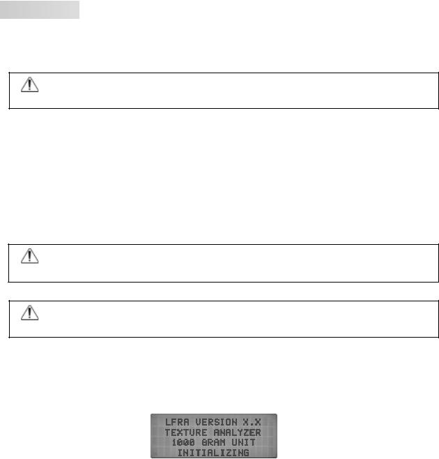
7)Turn the power switch to the ON position. The startup screen will indicate the firmware version and load range of the LFRA (Figure II.1).
Figure I.1
8)Allow the instrument to warm up for 10 minutes. Check calibration according to Section III.8.
Brookfield Engineering Labs., Inc. |
Page 5 |
Manual No. M/05-370-A1205 |


 I.6 Safety Symbols and Precautions


Safety Symbols
The following explains safety symbols which may be found in this operating manual.
Indicates hazardous voltages may be present.
Refer to the manual for specific warning or caution information to avoid personal injury
or damage to the instrument.
Precautions
If this instrument is used in a manner not specified by the manufacturer, the protection
provided by the instrument may be impaired.
This instrument is not intended for use in a potentially hazardous environment.
In case of emergency, turn off the instrument and then disconnect the electrical cord from the wall outlet.
The user should ensure that the substances placed under test do not release poisonous, toxic or flammable gases or liquids at the temperatures which they are subjected to during the testing.
Brookfield Engineering Labs., Inc. |
Page 6 |
Manual No. M/05-370-A1205 |


 I.7 Key Functions


The LFRA Texture Analyzer is operated through two keys and a knob located on the keypad. Additionally, there is an emergency stop button located on the base.
RESET / STOP
This key is used to stop a test in progress.
START
This key is used to start the test. During the descent of the probe, prior to the trigger point, this key can be used to accelerate the rate of descent.
Display
Keypad
SELECT / SCROLL
This knob has multiple functions:
1.The knob is pressed to select the option currently displayed.
2.The knob is rotated to vary the value of the parameter being selected.
3.During a test, pressing this knob will display test parameters.
EMERGENCY STOP
Figure I.2
This button is used to abort a test in case of an emergency condition.

 I.8 Cleaning


Base Table
 Emergency Stop
Instrument and Keypad: |
Clean with a dry, nonabrasive cloth. Do not use solvents |
|
or cleaners. |
Probes and Fixtures: |
Probes and fixtures are made from a variety of materials |
|
from metals (stainless steel, aluminum) to plastics (ac- |
|
etate, Perspex, Nylon). Clean with a nonabrasive cloth |
|
using solvents that are appropriate for both the sample |
|
material and the material of the probe and/or fixture. |
Do not apply excessive upward, downward or sideways force. Damage may occur to the load cell.
Brookfield Engineering Labs., Inc. |
Page 7 |
Manual No. M/05-370-A1205 |

II.QUICK START
1.Unpack the instrument according to Section I.5.
2.Attach the selected probe. See Section IV.2 for more information.
3.Place the sample on the base table. Adjust the table height so that the surface of the sample is within 5 mm of the probe (see Section III.3).
4.Set the test mode to Normal See Section III.6 for more information.
5.Set the trigger value to 0.5% of the load cell range. For example, use 5g for a 1000g load cell instrument.
6.Set the test speed and distance. See Section IV.3 for more information.
7.Press the START button.
8.Record the Peak Load and/or Final Load in grams.
9.Clean the probe and remove sample.
Brookfield Engineering Labs., Inc. |
Page 8 |
Manual No. M/05-370-A1205 |

III. OPERATION

 III.1 Principle


The Brookfield LFRA Texture Analyzer drives a probe through a set distance at a set speed into a sample material that is placed (or fixed) on the base table. The LFRA offers a variety of probes, fixtures, and test parameters to provide the user with a range of options for evaluating the texture of a sample material. The following section describes the use of the LFRA to conduct a test.

 III.2 Emergency Stop


The LFRA Texture Analyzer can operate with up to 4500g (4.5 kg) of force depen-
dent on load cell. Be sure to place only the sample for test under the probe. Keep body parts and clothing away from the probe during the test.
The LFRA Texture Analyzer uses a compression force to evaluate a material. The user must take care not to place any body part or clothing in the compression zone. The LFRA Texture Analyzer is provided with an Emergency Stop Button for use in case of an operational problem.
Pressing the Emergency Stop Button will cause three immediate actions: 1) Stop the test in progress. 2) Return the probe to the top most position. 3) Reset the LFRA to the Emergency Stop display, Figure III.1.
Figure III.1
The Emergency Stop condition can be canceled by rotating the Emergency Stop Button clockwise. This will reset the LFRA firmware to the power up condition.
Brookfield Engineering Labs., Inc. |
Page 9 |
Manual No. M/05-370-A1205 |
Loading...