


 BROOKFIELD CAP
 2000+
2000+


Viscometer
Operating Instructions
Manual No. M02-313-G0812
SPECIALISTS IN THE
MEASUREMENT AND
CONTROL OF VISCOSITY
with o ces in: Boston • Chicago • London • Stuttgart • Guangzhou
BROOKFIELD ENGINEERING LABORATORIES, INC.
11 Commerce Boulevard, Middleboro, MA 02346 USA
|
TEL |
508-946-6200 |
or 800-628-8139 (USA e xcluding MA) |
|
||
|
FAX |
508-946-6262 |
INTERNET http://www.brook eldengineering.com |
|
||
|
|
|
|
|
|
|
|
Brookfield Engineering Labs., Inc. |
|
Page 1 |
Manual No. M02-313-G0812 |
|
|
|
|
|
|
|
|
|

Table of Contents
I. INTRODUCTION................................................................................................................................... |
5 |
|
I.1 |
Components..................................................................................................................................................................... |
5 |
I.2 |
Utilities................................................................................................................................................................................ |
6 |
I.3 |
Specifications.................................................................................................................................................................... |
6 |
I.4 |
Dimensional Details....................................................................................................................................................... |
8 |
I.5 |
Installation......................................................................................................................................................................... |
9 |
I.6 Safety Symbols and Precautions............................................................................................................................ |
10 |
|
I.7 |
Key Functions................................................................................................................................................................ |
10 |
I.8 |
Viscosity and Temperature Display........................................................................................................................ |
11 |
I.9 |
Cleaning.......................................................................................................................................................................... |
11 |
II. GETTING STARTED............................................................................................................................ |
12 |
|
II.1 |
Power ON....................................................................................................................................................................... |
12 |
II.2 |
Cone Spindle Selection and Setting..................................................................................................................... |
13 |
II.3 |
Speed Setting............................................................................................................................................................... |
14 |
II.4 |
Temperature Control Setting.................................................................................................................................. |
15 |
II.5 |
Hold Time Settings..................................................................................................................................................... |
15 |
II.6 |
Run Time......................................................................................................................................................................... |
15 |
II.7 |
Printing........................................................................................................................................................................... |
16 |
II.8 |
Run and Stop Keys...................................................................................................................................................... |
16 |
II.9 |
Parameter Display....................................................................................................................................................... |
17 |
III. OPERATION........................................................................................................................................ |
18 |
|
III.1 |
Full Scale Range and Accuracy of Measurement............................................................................................ |
18 |
III.2 |
Accuracy of Viscosity and Temperature............................................................................................................. |
19 |
III.3 |
Calibration Verification............................................................................................................................................. |
21 |
III.4 |
Cone Calibration......................................................................................................................................................... |
23 |
III.5 |
Repeatability................................................................................................................................................................ |
25 |
III.6 |
Making Viscosity Measurements.......................................................................................................................... |
26 |
III.7 |
Computer Control...................................................................................................................................................... |
28 |
APPENDIX A - Variables in Viscosity Measurement...................................................................................................... |
29 |
|
APPENDIX B - Communications.......................................................................................................................................... |
31 |
|
APPENDIX C - Online Help and Additional Resources................................................................................................ |
35 |
|
APPENDIX D - Packing Instructions to Return a Brookfield CAP Viscometer for Repair or Calibration.................... |
36 |
|
APPENDIX E - Warranty Repair and Service.................................................................................................................... |
37 |
|
This manual intended for use with CAP 2000+ series viscometers which have serial numbers beginning with a prefix of “CPN” .
CAP1000 and 2000 Viscometers with a serial number prefix of “CP” require a different manual. Please contact Brookfield or your authorized dealer/representative to obtain this manual.

I.INTRODUCTION
The CAP 2000+ Series Viscometers are medium to high shear rate instruments with Cone Plate geometry and integrated temperature control of the test sample material. Rotational speed selection ranges from 5 to 1000 RPM. Viscosity measurement ranges depend upon the cone spindle and the rotational speed (shear rate). Viscosity is selectively displayed in units of centipoise (cP), poise (P), milliPascal seconds (mPa•s) or Pascal seconds (Pa•s). Temperature control of sample is possible between either 5°C (or 15°C below ambient, whichever is higher) and 75°C or 50°C and 235°C depending on viscometer model.
The CAP 2000+ Viscometer can display either CGS or SI units:
Viscosity: |
CGS |
SI |
Comment |
P or cP |
Pa•s or mPa•s |
0.1 Pa•s = 1 P (= 100 cP) |
|
Shear Rate: |
Sec-1 |
Sec-1 |
|
Speed: |
RPM |
RPM |
|
Temperature: |
°C |
°C |
|
The CAP 2000+ Viscometer outputs data to a parallel printer in the CGS and SI units:
|
CGS |
SI |
Comment |
Viscosity: |
P or cP |
Pa•s or mPa•s |
0.1 Pa•s = 1 P (= 100 cP) |
Full Scale Range (F.S.R.): |
% |
% |
|
Shear Stress: |
Dynes/cm2 |
N/m2 |
1.0 N•m = 107 dyne•cm |
Shear Rate: |
Sec-1 |
Sec-1 |
|
Speed: |
RPM |
RPM |
|
Run Time: |
Seconds |
Seconds |
|
Temperature: |
°C |
°C |
|
Cone Spindle Number: |
No. |
No. |
|
I.1 Components
The following items are included; see Figure I-1
1. |
CAP 2000+ Viscometer |
Part No. |
|
||
2. |
Cone Spindle(s)........................................ |
CAP-S-0X (X will be shown as a number 1-10) |
3. |
Spindle Case ........................................... |
CAP-106Y |
4. |
Solvent Trap ........................................... |
C1K-63 |
5. |
Foam Shipping Insert............................... |
CAP-122 |
6. |
Power Cord: 115V.................................. |
DVP-65 |
|
220V.................................. |
DVP-66 |
|
UK..................................... |
DE-8 |
|
Germany............................ |
DE-7 |
7. |
Operating Instructions Manual................. |
M02-313 |
The following optional items may have been included: |
Part No. |
|
|
|
|
8. Viscosity Standard Fluid for calibration |
See Table III-5 and III-6 in Section III |
|
Brookfield Engineering Labs., Inc. |
Page 5 |
Manual No. M02-313-G0812 |

Please check to be sure that you have received all components and that there is no damage.
If you are missing any parts, please notify Brookfield or your local dealer immediately. Any shipping damage must be reported to the carrier. Save the packing container, if possible, for future use when returning the viscometer to Brookfield or an authorized dealer for service.
Head |
Serial Tag Info |
|
on Back of |
||
|
||
|
Viscometer Head |
|
Thumb Screw |
Handle for Raising |
|
and Lowering |
|
|
P/N C1K-34Y |
Viscometer Head |
|
Solvent Trap |
|
|
P/N C1K-63 |
|
|
|
Column |
The Flat |
|
|
|
|
Foam Shipping Insert |
Cone Spindle |
|
P/N CAP-122 |
|
|
|
P/N CAP-S-XX |
Base |
|
|
|
|
|
Console |
|
|
Figure I-1: Components |
|
I.2 Utilities |
|
|
Input Voltage: |
115 VAC or 230 VAC |
|
Input Frequency: |
50/60 Hz |
|
Power Consumption: |
Less than 345 WATTS |
|
Fuses: |
(2) 5x20mm, 3A, 250V; Fast Acting for 125VAC |
|
|
(2) 5x20mm, 1.6A, 250V; Fast Acting for 250VAC |
|
Power Cord Color Code: |
United States |
Outside United States |
|
||
Hot (live) |
Black |
Brown |
Neutral |
White |
Blue |
Ground (earth) |
Green |
Green/Yellow |
Brookfield Engineering Labs., Inc. |
Page 6 |
Manual No. M02-313-G0812 |

I.3 Specifications |
|
|
|
Torque Range: |
Low 797-7,970 dyne•cm (designated on serial tag as 1/23 CAP) |
||
|
High 18,100-181,000 dyne•cm (designated on serial tag as CAP) |
||
Speeds: |
Variable speed from 5-1000 RPM |
|
|
Temperatures: |
CAP 2000+L 5°C (or 15°C below ambient, whichever is higher) to 75°C |
||
|
CAP 2000+H 50°C to 235°C |
|
|
|
All models provide 0.1°C increments |
|
|
Weight: |
Gross Weight |
36 lb |
16.3 kg |
|
Net Weight |
27 lb |
12.3 kg |
|
Carton Volume |
4.9 cu ft |
0.15 m3 |
|
Carton Dimensions |
18 in. L x 18 in. W x 26 in. H |
|
|
|
48 cm. L x 48 cm. W x 66 cm. H |
|
Materials: |
CAP cone spindles and temperature plates are made of tungsten carbide. |
||
|
Solvent Trap (P/N C1K-63) is made of teflon. |
||
Operating |
CAP 2000+ Viscometers must be operated within the following |
||
Environment: |
ambient temperatures: |
+5°C (41°F) to 40°C (104°F) |
|
|
and humidity: |
20% to 80% R.H. (non-condensing atmosphere) |
|
Electrical Certifications: |
BSEN 61326: |
Electrical equipment for measurement, |
Conforms to CE Standards: |
||
|
|
control and laboratory use - EMC |
|
|
requirements. |
NOTICE TO CUSTOMERS:
This symbol indicates that this product is to be recycled at an appropriate collection center.
Users within the European Union:
Please contact your dealer or the local authorities in charge of waste management on how to dispose of this product properly. All Brookfield offices and our network of representatives and dealers can be found on our website: www.brookfieldengineering.com.
Users outside of the European Union:
Please dispose of this product according to your local laws.
Brookfield Engineering Labs., Inc. |
Page 7 |
Manual No. M02-313-G0812 |

I.4 Dimensional Details
Brookfield Engineering Labs., Inc. |
Page 8 |
Manual No. M02-313-G0812 |
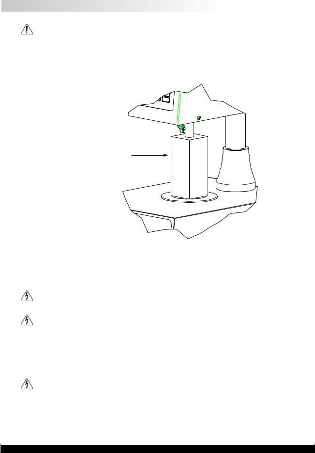
I.5 Installation
DO NOT lift the viscometer by the handle or head! LIFT only by the base console or column!
1)Set the viscometer on a clean level bench surface.
2)Removeshippingfoaminsert(P/NCAP-122)fromtheplateareaontheCAPViscometer. Store the foam insert for future use when shipping or transporting CAP Viscometer.
Foam Insert Used
When Shipping
CAP Viscometer
Figure I-2: Detail of Foam Insert
3)Verify that the viscometer’s power requirements match your power source BEFORE connecting it to power.
The AC input voltage and frequentcy must be within the appropriate range as shown on the back of the viscometer head.
Note: The CAP Viscometer must be earth grounded. Use the three (3) wire power cord! Do not alter!
4)Connect the power cord to the viscometer and to the power supply (source).
5)If using a printer, connect the printer cable to the printer port and printer.
Note: Ensure that both the printer and the CAP 2000+ are off when connecting cables.
Brookfield Engineering Labs., Inc. |
Page 9 |
Manual No. M02-313-G0812 |

I.6 Safety Symbols and Precautions
Safety Symbols
The following explains safety symbols which may be found in this operating manual.
Indicates hazardous voltages may be present.
Caution: HOT surface.
Refer to the manual for specific warning or caution information to avoid personal injury or damage to the instrument.
Safety Overview
If this instrument is used in a manner not specified by the manufacturer, the protection provided by the instrument may be impaired.
This instrument is not intended for use in a potentially hazardous environment.
In case of emergency, turn off the instrument and then disconnect the electrical cord from the wall outlet.
I.7 Key Functions
Figure I-3 shows the control keys on the face of the viscometer display panel:
NUMERIC 0 - 9
These keys are used for data entry
ENTER
This key accepts entered data.
STOP / ESCAPE
Stops cone spindle rotation at any time. Exits data entry field.
DELETE
This key clears entered values for input selections.
This key sends data to the parallel printer.
RUN
This key starts spindle rotation.
RUN TIME
This key selects time entry mode (time of spindle rotation).
CAP 2000+ VISCOMETER
Figure I-3
Brookfield Engineering Labs., Inc. |
Page 10 |
Manual No. M02-313-G0812 |
HOLD TIME
This key selects time entry mode (wait time before spindle rotates).
SPINDLE
This key selects the cone spindle entry mode.
TEMP
This key selects the temperature entry mode.
I.8 Viscosity and Temperature Display
Viscosity is displayed in either P=Poise or cP=Centipoise (CGS system) or Pa•s=Pascal seconds or mPa•s=milliPascal seconds (SI system). If the viscosity measurement is over range, “EEEE” will be displayed. Brookfield recommends a minimum torque reading of 10% when making viscosity measurements. If the torque value is between 0 and 10%, the display will flash to indicate an under range condition. If the viscometer final reading is below zero, negative values will be displayed.
Temperature is displayed in °C=degrees centigrade.
I.9 Cleaning
Instrument, Keypad & Painted Surfaces:
Clean with dry, non-abrasive cloth. Do not use solvents or cleaners.
Immersed Components (spindles/cones) and temperature controlled plate:
Note: Sample plate and spindle may be hot. Use care when using solvents.
All immersed components are made of carbide steel. Clean with non-abrasive cloth and solvent appropriate for sample material that is not aggressive to immersed components.
Do not use metal objects to clean the plate surface, as scratching of the plate may occur and comporomise cone calibrations.
Solvent Trap:
SolventTrap (P/N C1K-63) is made ofTeflon. Clean with non abrasive cloth and solvent
appropriate for sample material that is not aggressive to Teflon.
Do not use metal objects to clean the plate surface, as scratching of the plate may occur and compromise cone calibrations.
Immersed components (cone spindle) may be at an elevated temperature. Use caution when cleaning hot surfaces. Use caution when applying solvents to hot surfaces. Refer to the MSDS for the specific solvent for proper handling techniques.
Note: When cleaning, take care not to apply excessive force which may bend the spindle shaft or otherwise damage the instrument.
Brookfield Engineering Labs., Inc. |
Page 11 |
Manual No. M02-313-G0812 |

II.GETTING STARTED
II.1 Power On
Turn the power ON using the switch located on the rear of the base console.
The start-up screen will be displayed for four seconds and will indicate the viscometer model, version number and torque range.
BROOKFIELD |
|
BROOKFIELD |
CAP 2000+ VISCOMETER |
|
CAP 2000+ VISCOMETER |
VERSION 1.10 |
|
VERSION 1.10 |
1.0 CAP |
|
22.7 CAP |
Figure II-1A |
|
Figure II-1B |
Start-up Screen for High Torque CAP |
|
Start-up Screen for Low Torque CAP |
After four (4) seconds, the main screen will be displayed (Figure II-2).
0.00P |
0.0% |
Run 15 |
Spindle 04 |
50.0C |
900 RPM |
|
|
Figure II-2
The instrument will be set to the default temperature:
CAP L Series Viscometer |
25.0°C |
CAP H Series Viscometer |
50.0°C |
If the CAP 2000+ Viscometer is connected to a PC via the serial port on the rear of the base console, the main screen display is EXTERNAL.
Special Functions
Units of measure and speed control may be selected through the special functions screen. This screen is accessed by pressing the STOP key during instrument power up.
The CAP 2000+ can be configured to control speed by either rotations per minute (RPM) or shear rate (1/SEC). This selection is set by choosing 1=SPEED CONTROL in the special functions screen, then selecting 1=RPM or 2=1/SEC and pressing ENTER.
The CAP2000+ can be configured to display viscosity in one of four units: Poise (P), Centipoise (cP), Pascal Seconds (Pa•s) or milliPascal seconds (mPa•s). This selection is set by choosing 2=Units of Measure in the special functions screen, selecting 1=P, 2=cP, 3=Pa•s, or
4=mPa•s, and then pressing ENTER.
Once the CAP2000+ has been configured, the instrument must be turned OFF. The configuration will be stored in memory.
Note: When operating the CAP 2000+ with shear rate as the method of speed control, the shear rate value entered may be adjusted based on the shear rate multiplier for the spindle. For example: if using cone 4 (shear rate multiplier of 3.33), an entered shear rate of 51 1/SEC will be displayed as 50 1/SEC.
Brookfield Engineering Labs., Inc. |
Page 12 |
Manual No. M02-313-G0812 |
 Loading...