


BROOKFIELD CT3
TEXTURE ANALYZER
Operating Instructions
Manual No. M08-372-C0113
SPECIALISTS IN THE
MEASUREMENT AND
CONTROL OF VISCOSITY
with offices in: Boston • Chicago • London • Stuttgart • Guangzhou
BROOKFIELD ENGINEERING LABORATORIES, INC.
11 Commerce Boulevard, Middleboro, MA 02346 USA
TEL 508-946-6200 or 800-628-8139 (USA e xcluding MA) FAX 508-946-6262 INTERNET http://www.brookfieldengineering.com

|
|
Table of Contents |
|
I. |
INTRODUCTION.............................................................................................................. |
5 |
|
|
I.1 |
Components....................................................................................................... |
5 |
|
I.2 |
Utilities............................................................................................................... |
6 |
|
I.3 |
Units................................................................................................................... |
6 |
|
I.4 |
Specifications..................................................................................................... |
6 |
|
I.5 |
Installation......................................................................................................... |
7 |
|
I.6 |
Safety Symbols and Precautions........................................................................ |
8 |
|
I.7 |
Key Functions.................................................................................................... |
9 |
|
I.8 |
Cleaning........................................................................................................... |
11 |
II. |
QUICK START................................................................................................................. |
12 |
|
III. OPERATION.................................................................................................................... |
13 |
||
|
III.1 |
Principle........................................................................................................... |
13 |
|
III.2 |
Emergency Stop............................................................................................... |
13 |
|
III.3 |
Base Table........................................................................................................ |
14 |
|
III.4 |
Probes............................................................................................................... |
15 |
|
III.5 |
Fixtures............................................................................................................. |
15 |
|
III.6 |
Operating Menu................................................................................................ |
16 |
|
III.7 |
Running A Test................................................................................................. |
18 |
|
III.8 |
Texture Loader Software................................................................................... |
26 |
|
III.9 |
Checking Calibration......................................................................................... |
26 |
IV. TEST METHOD DEVELOPMENT................................................................................ |
29 |
||
|
IV.1 |
Sample Preparation............................................................................................ |
29 |
|
IV.2 |
Test Probe / Fixture............................................................................................ |
29 |
|
IV.3 Test Parameters.................................................................................................. |
30 |
|
|
IV.4 Recommendations............................................................................................. |
30 |
|
V. |
APPLICATIONS.............................................................................................................. |
31 |
|
|
V.1 |
Comparison of Low Fat and Virtually Fat Free Yogurt Consistencies............... |
31 |
|
V.2 A Comparison of the Textural Characterstics of Biscuits (Cookies).................. |
34 |
|
|
V.3 Review of Solid Chocolate at Ambient Temperature.......................................... |
36 |
|
Appendix A - Probes, Fixtures, Calibration Accessories and Gelatin Accessories |
........ 39 |
|
A-1 |
Probes...................................................................................................... |
39 |
A-2 |
Fixtures.................................................................................................... |
43 |
A-3 |
Calibration Accessories........................................................................... |
47 |
A-4 |
Gelatin Accessories.................................................................................. |
48 |
Appendix B - Troubleshooting....................................................................................... |
49 |
|
Appendix C - Texture Loader Programming................................................................. |
50 |
|
Appendix D - CT3 to Computer Command Set............................................................. |
52 |
|
Appendix E - Online Help and Additional Resources................................................... |
53 |
|
Appendix F - Warranty and Repair Service................................................................... |
54 |
|

I.INTRODUCTION
The CT3 Texture Analyzer is the most recent development of the original Boucher Jelly Tester. The original product was created as the Stevens Texturemeter and evolved into the CNS Farnell LFRATA
(LeatherheadFoodResearchAssociationTextureAnalyzer).BrookfieldEngineeringfirstenhanced the design of the LFRA, maintaining the characteristics of the original equipment, while expanding its measurement capabilities and ease of use by incorporating modern digital technology.
The new Brookfield CT3 TextureAnalyzer is the third generation of this venerable product, adding tension testing capability, increased load cell options, space for large samples, two options for base tables and a wider range of accessories for more flexibility. The main objective is to characterize your samples in a way that best represents their perception by human senses. This is the essence of texture analysis.
The principle of operation of the CT3TextureAnalyzer is to subject a sample to controlled forces in compression using a probe, or in tension using grips. The resistance of the material to these forces is measured by a calibrated load cell and shown in either grams or Newtons. These forces are a function of the properties of the sample and the parameters of the test method.
There are five load cell ranges available for the CT3 Texture Analyzer offered by Brookfield:
Model |
Load Cell Range |
CT3-100 |
0.1kg or 100g |
CT3-1000 |
1.0kg or 1000g |
CT3-1500 |
1.5kg or 1500g |
CT3-4500 |
4.5kg or 4500g |
CT3-10KG |
10.0kg |
CT3-25KG |
25kg |
CT3-50KG |
50kg |
I.1 Components
Please check to be sure that you have received all components, and that there is no damage. If you are missing any parts, please notify Brookfield Engineering or your local Brookfield agent immediately. Any shipping damage must be reported to the carrier.
Component |
Part Number |
Quantity |
CT3 Texture Analyzer |
varies |
1 |
Operating Manual |
M08-372 |
1 |
USB Cable |
DVP-202 |
1 |
Power Cord |
DVP-65 |
1 |
115 Volt or |
1 |
|
230 Volt |
DVP-66 |
1 |
TextureLoader CD |
CD-ProgA |
|
Probe Adapter M6 to M3 Threads |
TA51 |
1 |
Optional |
varies |
per order |
Probe |
||
Temperature Probe |
DVP-94Y |
1 |
Rotary Base Table |
TA-RT-KIT |
1 |
Fixture Base Table |
TA-BT-KIT |
1 |
Bloom Strip |
CT3-CS-100 or |
1 |
Calibration Weight Set |
CT3-CS-1000 |
1 |
varies by load cell |
||
Standard Probe Kit |
TA-P-KIT2 |
1 |
TexturePro CT Software |
TA-CT-PRO |
1 |
NOTE: Optional components may include probes or fixtures. See Appendix A for details.
Brookfield Engineering Labs., Inc. |
Page 5 |
Manual No. M08-372-C0113 |

I.2 Utilities |
|
|
|
Input Voltage: |
90-265 VAC |
|
|
Input Frequency: |
50/60 Hz |
|
|
Power Consumption: |
150 VA |
|
|
Fuse: |
Two 4 amp, 5 x 20mm, Time-lag |
||
Power Cord Color Code: |
United States |
Outside United States |
|
Hot (live) |
|||
Black |
Brown |
||
Neutral |
White |
Blue |
|
Ground (earth) |
Green |
Green/Yellow |
|
Main supply voltage fluctuations are not to exceed ±10% of the nominal supply voltage.
I.3 Units
The CT3 Texture Analyzer uses the SI system of units for all parameters.
Parameter |
Unit |
|
Abbreviation |
|
Load |
Grams or Newtons |
|
g or N |
|
Deformation |
Millimeter |
|
mm |
|
Time |
Seconds |
|
s |
|
Speed |
Millimeter per second |
mm/s |
||
Work |
MilliJoules |
|
mJ |
|
I.4 Specifications |
|
|
|
|
Load: |
Range |
Resolution |
|
|
Model |
Accuracy* |
|||
Grams |
Grams |
|||
CT3-100 |
0-100 |
0.01 |
±0.5%FSR |
|
CT3-1000 |
0-1000 |
0.10 |
±0.5%FSR |
|
CT3-1500 |
0-1500 |
0.20 |
±0.5%FSR |
|
CT3-4500 |
0-4500 |
0.50 |
±0.5%FSR |
|
CT3-10KG |
1-10000 |
1.0 |
±0.5%FSR |
|
CT3-25KG |
2-25000 |
2.0 |
±0.5%FSR |
|
CT3-50KG |
5-50000 |
5.0 |
±0.5%FSR |
|
FSR = Full Scale Range
*This value applies to the full range of operating temperatures as defined later in this section under Environmental Conditions. Accuracy is 0.2%FSR, when the instrument is operated in a stable ambient temperature (20°C - 25°C).
Brookfield Engineering Labs., Inc. |
Page 6 |
Manual No. M08-372-C0113 |

Trigger Point: |
Range |
Resolution |
|
Model |
|||
Grams |
Grams |
||
CT3-100 |
0.1-10 |
0.01 |
|
CT3-1000 |
0.2-100 |
0.10 |
|
CT3-1500 |
0.2-150 |
0.2 |
|
CT3-4500 |
0.5-500 |
0.5 |
|
CT3-10KG |
1-1000 |
1.0 |
|
CT3-25KG |
2-2500 |
2.0 |
|
CT3-50KG |
5-5000 |
5.0 |
Recommended trigger value settings are given in Table II.1
NOTE: Setting a trigger value of zero disables trigger function so test will immediately start from current position.
Speed: 0.01 to 0.1 mm/s in increments of 0.01 mm/s
0.1 to 10 mm/s in increments of 0.1 mm/s
Accuracy: ±0.1% of set speed
Position: |
Range: 0-101.6 mm |
|
Resolution: 0.1mm |
|
Accuracy: 0.1mm |
Increments for changing test speed using the Select/Scroll knob can be switched between 0.1mm/s and 1.0mm/s by depressing Reset/Stop button.
Temperature: |
-20°C to 120°C (Requires optional probe, DVP-94Y) |
Output: |
RS232 Compatible Serial Port, USB Port |
Environmental |
0°C to 40°C temperature range (41°F to 104°F) |
Conditions: |
20% - 80% relative humidity, non-condensing atmosphere |
Use: |
Intended for indoor use only |
|
Altitude: up to 2000m |
Dimensions: |
10.5” x 10.5” x 24” |
Weight: |
37 lbs. (16.8 kg) |
I.5 Installation
1) Prepare a clean, level surface.
NOTE: This instrument is a sensitive force measuring device. It should be installed on a clean, solid, level bench surface which is free from external vibrations.
2) Unpack and remove the CT3 Texture Analyzer from the shipping container.
The CT3 Texture Analyzer weighs 16.8 kg (37 pounds). Use caution when lifting the unit out of the packaging.
3)Place the CT3 Texture Analyzer on a sturdy, level surface. Adjust the four feet to ensure that the instrument is stable.
Brookfield Engineering Labs., Inc. |
Page 7 |
Manual No. M08-372-C0113 |

4)Remove any additional components from the shipping package. Save the shipping container and packaging for future use.
5)Install base table using the supplied pair of T-bolts and thumbscrews. Position the base table so that it is approximately centered under the probe. More accurate alignment may be required for certain fixtures.
6)Make sure that the AC power switch at the rear of the CT3 Texture Analyzer is in the OFF
|
|
position. Connect the power cord to the socket on the back panel of the instrument |
|
l |
on |
and plug it into the appropriate AC line. Position instrument so that the power |
|
o |
|||
off |
cord can be removed easily. |
||
|
The AC input voltage and frequency must be within the appropriate range as shown on the model and serial tag of the instrument (located on the back of the CT3).
The CT3 Texture Analyzer must be earth grounded to ensure against electronic failure!
7)If appropriate, connect communication cable which is supplied with Texture Loader software to the appropriate port for connection to a computer.
8)Turn the power switch to the ON position. The startup screen will indicate the firmware version and load range of the CT3 (Figure I.1).
CT3 VERSION X.X
TEXTURE ANALYZER
XXXX GRAM UNIT
INITIALIZING
Figure I.1
9)Allow the instrument to warm up for 10 minutes.
10)If desired, check calibration according to Section III.9.
I.6 Safety Symbols and Precautions
Safety Symbols
The following explains safety symbols which may be found in this operating manual, or on the instrument itself.
Indicates hazardous voltages may be present.
Refer to the manual in all cases where this symbol is evident. Used for specific warning or caution information to avoid personal injury or damage to the instrument.


 Keep hands, fingers and other body parts clear of moving parts when operating instrument.
Brookfield Engineering Labs., Inc. |
Page 8 |
Manual No. M08-372-C0113 |
Functional Earth Terminal - Main power entry module must have an earth conductor.
Precautions
If this instrument is used in a manner not specified by the manufacturer, the protection provided by the instrument may be impaired.
This instrument is not intended for use in a potentially hazardous environment.
In case of emergency, turn off the instrument and then disconnect the electrical cord from the wall outlet.
The user should ensure that the substances placed under test do not release poisonous,
toxic or flammable gases or liquids at the temperatures which they are subjected to during the testing.
I.7 Key Functions
The CT3 Texture Analyzer is operated through two keys and a knob located on the keypad. Additionally, there is an emergency stop button located above the base and to the right of the probe rod.
Reset
Stop
Probe
Adapter
CT3 TEXTURE ANALYZER
BROOKFIELD
Display
Select/Scroll
Start
Emergency
 Stop
Stop
Figure I.2
Brookfield Engineering Labs., Inc. |
Page 9 |
Manual No. M08-372-C0113 |

RESET / STOP
This key is used to stop a test in progress and return to starting position. This button will also toggle test speed selections between 0.1mm/ss and 1.0mm/s as the Select/Scroll knob is rotated.
START
This key is used to start the test. During the descent of the probe, prior to the trigger point, this key can be used to accelerate the rate of descent.
SELECT / SCROLL (see section III.6)
This knob has multiple functions:
1.The knob is pressed to select the option currently highlighted.
2.The knob is rotated to change the value of the parameter being selected.
3.During a test, pressing this knob will display test parameters.
4.Holding knob depressed while turning on power will switch the load display units between grams and Newtons.
EMERGENCY STOP
This button is used to abort a test in case of an emergency condition.
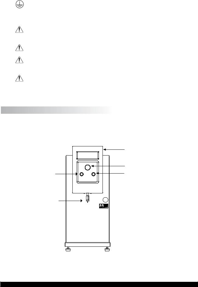
BACK PANEL
1) USB Type B Port |
|
3) |
Temperature Probe Plug |
2) RS-232 Serial Port |
|
4) |
Power Entry Module |
|
Power ON/OFF Switch |
Figure I.3
1) USB TYPE B PORT
Use with USB Cable P/N DVP-202 to connect instrument to a computer. Cable USB 2.0 A Male
Brookfield Engineering Labs., Inc. |
Page 10 |
Manual No. M08-372-C0113 |
to B Male. See Appendix D, (CT3 to Computer Command Set) 2) RS-232 Serial Port
Use with RS-232 Cable P/N DVP-80 to connect instrument to a computer. See Appendix D, (CT3 to Computer Command Set)
3)Temperature Probe Plug - 4 pin plug. Use with Temperature Probe P/N DVP-94Y
4)Power Entry Module: ON/OFF switch-fused (see I.2 Utilities). Voltage: 90-265 VAC
I.8 Cleaning |
|
Instrument and Keypad: |
Clean with a dry, nonabrasive cloth. Do not use solvents |
|
or cleaners. |
Probes and Fixtures: |
Probes and fixtures are made from a variety of materials |
|
frommetals (stainlesssteel, aluminum) toplastics (acrylic, |
|
Black Delrin, Nylon). Clean with a nonabrasive cloth |
|
using solvents that are appropriate for both the sample |
|
material and the material of the probe and/or fixture. |
Do not apply excessive upward, downward or sideways force to probe while fixed to
CT3. Damage may occur to the load cell.
Brookfield Engineering Labs., Inc. |
Page 11 |
Manual No. M08-372-C0113 |

II.QUICK START
1.Unpack the instrument according to Section I.5.
2.Install base table in accordance with the instruction sheet that is enclosed with the base table. Place the sample on the base table. Adjust the table height so that the surface of the sample is within 5 mm of the probe.
3.Attach the selected probe. See Section IV.2 for more information.
4.Set the test mode to Normal. Please review section III.6 for detailed explanation of operation of Select/Scroll knob.
5.Set the trigger value as recommended below.
Load Cell |
Recommended Minimum |
|
Trigger Value |
||
|
||
100g |
0.5g |
|
1000g |
2g |
|
1500g |
3g |
|
4500g |
4.5g |
|
10kg |
10g |
|
25kg |
25g |
|
50kg |
50g |
Table II.1
6.Set the test speed and distance. See Section IV.3 for more information.
7.Press the START button. The weight of the probe will autozero and then the test will start.
8.Record all test results.
9.Remove sample and clean the probe.
Brookfield Engineering Labs., Inc. |
Page 12 |
Manual No. M08-372-C0113 |

III.OPERATION
III.1 Principle
The Brookfield CT3 Texture Analyzer can be operated in either compression or tension modes.
In compression mode a probe moves down slowly at pretest speed until a threshold value (the trigger) is reached. The probe then moves a set distance at a set speed into the sample material that is placed (or fixed) on the base table. The load is continuously monitored as a function of both time and distance until the probe again returns to its starting position.
In tension mode the sample is typically held between a pair of grips. The test starts when the trigger load is reached as the grips move apart. The load resistance as the sample is stretched or pulled apart is recorded as a function of both time and distance.
III.2 Emergency Stop
The CT3 Texture Analyzer can operate with up to 50,000g (50kg) of force dependent on load cell. Be sure to place only the sample for test under the probe.
Keep body parts and clothing away from the probe during the test.
The CT3 Texture Analyzer uses controlled forces to evaluate a material. The user must take care not to place any body part or clothing in the testing zone while the machine is moving. The CT3 Texture Analyzer is provided with an Emergency Stop Button (see Figure I.2) for use in case of an operational problem.
Pressing the Emergency Stop Button will cause different immediate actions depending upon the type of test in use.
Compression: Pressing Emergency Stop Button during a compression test will:
1) Stop the test in progress and display emergency stop screen.
EMERGENCY STOP
RESET EMERGENCY STOP
Figure III.1
2)The probe immediately returns to the home position.
3)The Emergency Stop condition can be canceled by rotating the Emergency Stop Button clockwise. This will reset the CT3 firmware to the power up condition.
Tension: Pressing Emergency Stop Button during a tension test will:
Brookfield Engineering Labs., Inc. |
Page 13 |
Manual No. M08-372-C0113 |

1)Immediately stop probe movement and display the emergency stop screen.
2)Probe returns to test start position, after resetting the emergency stop.
3)A sequence of menus then leads user back to the home position.
III.3 Base Table
The CT3 Texture Analyzer offers two options for Base Tables on which the test sample is placed. Both tables should be secured to the slotted base of the CT3 with thumbscrews and T-bolts. This design provides ample adjustment side-to-side and front-to-back to correctly align fixtures and position a wide range of samples for testing.
NOTE: Always be sure all position and height adjustments are securely locked before starting every test.
BROOKFIELD |
BROOKFIELD |
 Rotary Base Table
(TA-RT-KIT)
Fine Adjustment Nut |
Fixture Base Table |
|
(TA-BT-KIT) |
Locking Knob |
|
Figure III.2
See Appendix A for fixtures which can be used with each Base Table.
Rotary Base Table
The Rotary Base Table (P/N TA-RT-KIT) is a disc shaped surface and should always be centered under the probe when conducting compression tests. There are two methods of adjusting the height in order to place the sample close to the probe for testing. The locking knob on the base of the
RotaryTableallowsquickheightadjustment;justunlocktheknob,raiseorlowerthetable,thenlock
Brookfield Engineering Labs., Inc. |
Page 14 |
Manual No. M08-372-C0113 |

it into position. The table is also mounted on a threaded shaft held securely with a fine adjustment nut. Unlocking the fine adjustment nut and rotating the table will raise or lower the test surface to give even more range to the height adjustment.
Always hold the Rotary Base Table with one hand while loosening the Locking Knob. This will prevent the Rotary Base Table from falling abruptly to the CT3 housing.
Keep fingers away from the Fine Adjust Nut when lowering the Rotary Base Table to prevent a pinch injury.
Fixture Base Table
The Fixture Base Table (P/N TA-BT-KIT) is a rectangular test surface with a removable center.
Many of the test fixtures fit into this center area so this table becomes the mounting base for these sample test fixtures. The Fixture Base Table is supplied with a variety of extension legs to set the test surface at the correct height for all accessory fixtures. Some disassembly is required to add or
remove extension legs by loosening the Phillips head bolts in the underside of the base table.
III.4 Probes
There are a wide range of probes available for use with the CT3 Texture Analyzer as described in Appendix A. One should always be aware that the probe chosen will have an impact upon the test result. Choice of a probe must be made with consideration toward the purpose of the test
and the nature of the sample.
The probes may be cleaned while attached to the CT3. Follow recommendations in Section I.8.
Always attach probes only finger tight to prevent thread damage. Do not apply excessive upward, downward or sideways force. Damage may occur to the load cell.
Inspect a probe before use for any damage and always handle them carefully as some have sharp points or edges. Most probes require the TA51 thread adapter to attach to the CT3. This adapter is installedatthefactorybeforeyourinstrumentwasshipped. Afewprobesandmostaccessoryfixtures require removal of the probe adapter. Keep it in a safe place as it is needed for most probes.
III.5 Fixtures
There are a range of fixtures available for use with the CT3 Texture Analyzer as described in
Appendix A. These devices are designed to hold a sample in place during measurement. Each fixture is designed to attach to either the Rotary Base or Fixture Base Table. Refer to the instructions provided with the fixture for proper installation.
NOTE:Brookfield can design custom fixtures to meet your application. Contact Brookfield or our authorized dealer for details.
Brookfield Engineering Labs., Inc. |
Page 15 |
Manual No. M08-372-C0113 |

III.6 Operating Menu
The CT3 Texture Analyzer offers seven test modes, one calibration mode and one parameter selection table.
Each test mode requires parameters to be set. All test mode selection and parameter setting is done using the Select/Scroll knob (see figure 1.2). This knob is both rotated and depressed during operation.
NOTE:When setting the test speed, pressing the RESETbutton will toggle the increments from
0.1mm/s to 1mm/s.
The specific parameters required will depend upon the type of test chosen:
Normal Test Requires: |
trigger, deformation, speed |
Hold Time Test Requires: |
hold time, trigger, deformation, speed |
Cycle Count Test Requires: |
cycle count, trigger, deformation, speed |
Bloom Test Requires: |
All parameters are fixed according to industry standard |
TPATest Requires: |
trigger, deformation, speed |
Tension Test Requires: |
trigger, deformation, speed |
Surimi Test Requires: |
trigger, correction, speed |
Static Load Test Requires: |
none |
Global Paramters: |
pretest speed, post test speed, temperature units |
These parameters, once set, will be maintained by the CT3 even after power down to facilitate repetitive testing. The test mode used prior to powering down will be presented on the screen at the next power up. A test is started by depressing the start button.
The test parameters are defined as follows:
Trigger: The load, in grams, measured by the CT3 to indicate that the probe is in contact withthesample.Oncethetriggervalueisreached,thetestwillbeginatthedefined speed. Brookfield recommends trigger values as specified in Table II.1 Setting trigger value to zero disables trigger function so test will immediately start from current position.
Deformation: The total downward distance the probe will travel once the trigger value is reached.
Speed: The speed at which the probe will travel the specified distance.
Time: The number of seconds that the probe will be held at the defined distance during a Hold Time test.
Count: The number of cycles (Speed and Distance) that will be applied to the sample during a Cycle Count test.
Correction: Specifies the size of the load drop, in grams, that is required to recognize a gel rupture.
Brookfield Engineering Labs., Inc. |
Page 16 |
Manual No. M08-372-C0113 |

All parameters can be set within the ranges shown in Table III.1.
Load Cell Range
Parameter |
100g |
1000g |
1500g |
4500g |
10kg |
25kg |
50kg |
||||||||||||||
Trigger* |
0.1 |
– 10g |
0.1 |
– 100g |
0.2 |
– 150g |
0.5 |
– 500g |
1-1000g |
2-2500g |
5-5000g |
||||||||||
Deformation (mm) |
0.1 |
– 101.6 |
0.1 |
– 101.6 |
0.1 |
– 101.6 |
0.1 |
– 101.6 |
0.1 |
– 101.6 |
0.1 |
– 101.6 |
0.1 |
– 101.6 |
|||||||
Speed (mm/s) |
0.01 – 10 |
0.01 – 10 |
0.01 – 10 |
0.01 – 10 |
0.01 – 10 |
0.01 – 10 |
0.01 – 10 |
||||||||||||||
Hold Time |
0 |
– |
9999 s |
0 |
– |
9999 s |
0 |
– |
9999 s |
0 |
– |
9999 s |
0 |
– |
9999 s |
0 |
– |
9999 s |
0 |
– |
9999 s |
Cycle Count |
0 |
– |
99 |
0 |
– |
99 |
0 |
– |
99 |
0 |
– |
99 |
0 |
– |
99 |
0 |
– |
99 |
0 |
– |
99 |
Correction |
5 |
– |
99 |
5 |
– |
99 |
5 |
– |
99 |
5 |
– |
99 |
N/A |
N/A |
N/A |
||||||
* Minimum recommended values for trigger are shown in Table II.1.
Table III.1
Define a test by first selecting a test mode. Rotate the Select / Scroll knob until the required test mode is displayed, then press the Select / Scroll knob to confirm your choice. As the test modes are displayed, the parameters specific to that mode will be shown with the previously selected parameters.
Once a test mode is selected, the cursor will move to the first parameter. You may either select that parameter to enter new values by pressing the Select / Scroll knob or you may scroll to the next parameter by rotating the Select / Scroll knob.
Data entry is accomplished by setting each digit individually. For example: to set a value of 57.0 as the target distance, rotate the Select / Scroll Knob until the “D” in “Distance” is blinking. Depress the Select / Scroll knob to get to the tens digit, then rotate the knob to the value 5. Depress the Select / Scroll knob again to get to the ones digit, then rotate the knob to the value 7. Depress the Select / Scroll knob to get to the tenths digit, and depress it again to leave the value at 0.
A data entry of zero in all columns for any parameter will result in that parameter being reset to the previous value. Pressing the Select / Scroll knob without first rotating it during the data entry process will result in a zero being placed in that column. This can expedite the entry of Trigger
values since in most cases the first one or two columns will be zero (004.0 grams).
Display Conventions
The CT3 display contains four lines, but some result screens contain additional lines of information. In order to show more than four lines of information, screens are allowed to scroll using the Scroll
knob. Scrollable screens are identified by the symbols in the upper right corner of the display. Whenever these symbols appear, the display can be scrolled up or down as indicated to show the lines above or below those presently displayed. In the following section describing test modes, all possible displays are shown. For those having more than four lines, the additional lines are shown
in grey text as seen in figure III.3.
HARDNESS1: XXXX.X g HARDNESS2: XXXX.X g COHESIVENESS: XXX.XX SPRINGINESS: XX.X mm
ADHESION: |
XX.X mJ |
TEMP: |
XXX.X F |
HARDNESS1: XXXX.X N HARDNESS2: XXXX.X N COHESIVENESS: XXX.XX SPRINGINESS: XX.X mm
ADHESION: |
XX.X mJ |
TEMP: |
XXX.X C |
Force shown in grams |
Force shown in Newtons |
|
Figure III.3 |
Brookfield Engineering Labs., Inc. |
Page 17 |
Manual No. M08-372-C0113 |
 Loading...