


DV-III Ultra Rheometer

Brookeld Engineering Laboratories, Inc. Page 1 Manual No. M98-211-E0912
BROOKFIELD DV-III ULTRA
Programmable Rheometer
Operating Instructions
Manual No. M98-211-E0912
SPECIALISTS IN THE
MEASUREMENT AND
CONTROL OF VISCOSITY
TEL 508-946-6200
F
AX 508-946-6262
or 800-628-8139 (USA e xcluding MA)
I
NTERNET
http://www.brookfieldengineering.com
BROOKFIELD ENGINEERING LABORATORIES, INC.
11 Commerce Boulevard, Middleboro, MA 02346 USA
with offices in
:
Boston • Chicago • London • Stuttgart • Guangzhou

Brookeld Engineering Laboratories, Inc. Page 2 Manual No. M/98-211-B0104
Brookeld Engineering Laboratories, Inc. Page 2 Manual No. M98-211-E0912

Brookeld Engineering Laboratories, Inc. Page 3 Manual No. M/98-211-B0104
Brookeld Engineering Laboratories, Inc. Page 3 Manual No. M98-211-E0912
Table of Contents
I. Introduction .......................................................................................................... 5
I.1 Torque Measurement ................................................................................................................. 5
I.2 Viscosity Units of Measurement ................................................................................................5
I.3 Yield Stress Measurement ........................................................................................................6
I.4 Components ..............................................................................................................................7
I.5 Dimensional Information ............................................................................................................ 8
I.6 Utilities ....................................................................................................................................... 9
I.7 Specication ..............................................................................................................................9
I.8 Safety Symbols and Precautions ............................................................................................. 11
I.9 Data Retention ......................................................................................................................... 11
I.10 Set-Up ................................................................................................................................... 11
I.11 Connections ........................................................................................................................... 15
I.12 Key Functions ........................................................................................................................ 16
I.13 Cleaning .................................................................................................................................17
II. Getting Started ................................................................................................... 18
II.1 Autozero .................................................................................................................................18
II.2 Rheometer Display ................................................................................................................. 18
II.3 Spindle Entry ..........................................................................................................................21
II.4 Direct Speed Entry .................................................................................................................23
II.5 External Control ...................................................................................................................... 24
II.6 Preventative Maintenance ...................................................................................................... 25
III. Making Viscosity and Yeild Measurements .................................................... 27
III.1 Quick Start ............................................................................................................................. 27
III.2 Preparations for Making Measurements ................................................................................28
III.3 Selecting a Spindle/Speed ....................................................................................................30
III.4 Multiple Data Points ...............................................................................................................30
IV. Programming the DV-III Ultra and Data Collection Methods/Analysis ......... 31
IV.1 Programming Concepts ......................................................................................................... 31
IV.2 DV-III Speed/Time Pair Programs for Making Viscosity Measurements ...............................32
IV.3 Bevis Programs for Making Viscosity Measurements ...........................................................42
IV.3.1 Setting Up Bevis Programs ............................................................................................42
IV.3.1.1 Description of B.E.V.I.S. Commands ......................................................................43
IV.3.1.2 Example Programs ................................................................................................. 46
IV.3.2 Running Bevis Programs in Standalone Mode ............................................................... 47
IV.4 Choosing the Best Data Collection Method for Viscosity Tests ............................................. 49
IV.5 Data Analysis for Viscosity Tests ........................................................................................... 50
IV.6 Automated Data Gathering and Analysis using Rheocalc .....................................................50
IV.7 Math Models ..........................................................................................................................50
IV.7.1 The Power Law (Ostwald) Model ...................................................................................42
IV.7.2 The Herschel/Bulkley Model ...........................................................................................42
IV.7.3 The Bingham Model .......................................................................................................42
IV.7.4 The Casson Model .........................................................................................................42

Brookeld Engineering Laboratories, Inc. Page 4 Manual No. M98-211-E0912
IV.7.5 Other Common Rheological Models ..............................................................................42
IV.8 Yeild Stress Test Programs and Test Samples ...................................................................... 53
IV.8.1 Test Parameter Description ............................................................................................ 53
IV.8.2 Toolbar and Menu Options .............................................................................................57
IV.8.3 Data Page ......................................................................................................................60
IV.8.4 Graphs Page ..................................................................................................................62
IV.8.5 Examples of Yield Test Programs ................................................................................... 65
IV.8.5.1 Example Application: Hair Gel .............................................................................. 65
IV.8.5.2 Example Application: Hand Cream ....................................................................... 66
IV.8.5.3 Example Application: Ketchup .............................................................................. 66
IV.8.5.4 Torque vs. Time for Various Food Products ........................................................... 68
IV.8.6 Running Yield Test Programs in Stand-Alone Mode ..................................................... 69
IV.8.6.1 Data Output ...........................................................................................................73
IV.8.6.2 Printing A Program ................................................................................................73
IV.8.6.3 Test Results ........................................................................................................... 75
V. OPTIONS ............................................................................................................. 77
V.1 Set Up ....................................................................................................................................77
V.2 Print ........................................................................................................................................77
V.3 Alarm ......................................................................................................................................78
V.4 Set Temperature ..................................................................................................................... 79
V.5 Data ........................................................................................................................................79
V.6 Timed Data Collection ............................................................................................................81
Appendix A - Cone/Plate Rheometer Set-Up ...................................................................83
A.1 Electronic Gap Setting Features ............................................................................................83
A.2 Set-Up .....................................................................................................................................84
A.3 Setting the Gap .......................................................................................................................85
A.4 Verifying Calibration ................................................................................................................86
Appendix B - Viscosity Ranges ........................................................................................87
Appendix C - Variables in Viscosity Measurements .......................................................93
Appendix D1 - Spindle and Model Codes for Viscosity Tests .......................................95
Appendix D2 - Spindle Codes and Speeds for Yeild Tests ............................................99
Appendix E - Calibration Procedures .............................................................................102
Appendix F - The Brookeld Guardleg ..........................................................................107
Appendix G - DV-III Ultra Stand Assembly .....................................................................109
Appendix H - DVE-50A Probe Clip ..................................................................................110
Appendix I - DV-III Ultra to Computer Command Set .................................................... 111
Appendix J - Fault Diagnosis and Troubleshooting .....................................................115
Appendix K - Online Help and Other Resources ........................................................... 118
Appendix L - Warranty Repair and Service .................................................................... 119
Viscosity Test Report .........................................................................................Tear out page
Table of Contents (cont'd)

Brookeld Engineering Laboratories, Inc. Page 5 Manual No. M/98-211-B0104
Brookeld Engineering Laboratories, Inc. Page 5 Manual No. M98-211-E0912
The Brookeld DV-III Ultra Programmable Rheometer measures uid parameters of Shear Stress
and Viscosity at given Shear Rates. Viscosity is a measure of a uid’s resistance to ow. You will
nd a detailed description of the mathematics of viscosity in the Brookeld publication “More
Solutions to Sticky Problems”, a copy of which was included with your DV-III Ultra.
The principle of operation of the DV-III Ultra is to drive a spindle (which is immersed in the test
uid) through a calibrated spring. The viscous drag of the uid against the spindle is measured
by the spring deection. Spring deection is measured with a rotary transducer. The viscosity
measurement range of the DV-III Ultra (in centipoise or cP) is determined by the rotational speed
of the spindle, the size and shape of the spindle, the container the spindle is rotating in, and the full
scale torque of the calibrated spring.
The DV-III Ultra can also measure yield stress (in Pascals or Pa). See Section I.3 for more information
on yield stress.
I.1 Torque Measurement
There are four basic spring torque models offered by Brookeld:
Spring Torque
Model dyne•cm mN•m
LVDV-III Ultra 673.7 0.0673
RVDV-III Ultra 7,187.0 0.7187
HADV-III Ultra 14,374.0 1.4374
HBDV-III Ultra 57,496.0 5.7496
The higher the torque calibration, the higher the viscosity measurement range. The viscosity
measurement range for each spring torque model may be found in Appendix B.
I.2 Viscosity Units of Measurement
All units of measurement are displayed according to either the CGS system or the SI
system.
1. Viscosity appears in units of centipoise (shown as “cP”) or milliPascal-seconds (shown
as mPa•s).
2. Shear Stress appears in units of dynes/square centimeter (“D/cm
2
”) or Newtons/square
meter (“N/m
2
”).
3. Shear Rate appears in units of reciprocal seconds (“1/SEC”).
4. Torque appears in units of dyne-centimeters or Newton-meters (shown as percent “%”
in both cases).
The equivalent units of measurement in the SI system are calculated using the following
conversions:
SI CGS
Viscosity: 1 mPa•s = 1 cP
Shear Stress: 1 Newton/m
2
= 10 dyne/cm
2
Torque: 1 N•m = 10
7
dyne•cm
References to viscosity throughout this manual are done in CGS units.
I. INTRODUCTION
Brookeld Engineering Laboratories, Inc. Page 6 Manual No. M98-211-E0912
I.3 Yield Stress Measurement
Another feature now available in the DV-III Ultra Rheometer is the yield stress test.
The yield point is the point at which a material begins to ow. The associated properties are the
yield stress and yield strain. The yield stress is the critical shear stress, applied to the sample, at
which the material begins to ow as a liquid. The yield strain is the deformation in the material,
resulting from the applied stress prior to the start of ow.
Many materials are designed to have a yield point, so that the behavior of their products satises
various customer needs. Foods often have yield points. Ketchup in particular must ow out of a
bottle when shaken or squeezed, but then solidify on the targeted food such as french fries. Shaking
or squeezing the bottle stresses the ketchup so that it ows; after the ketchup settles on the fries, its
structure rebuilds so the ketchup “sits” in place rather than owing off the fries like water. Puddings
have yield points, as well. The “body” of the pudding appeals to consumers – it is solid at rest,
yet it’s easily spooned out of its cup and is easy to eat. Thus, the yield behavior of many foods
contributes to the food texture that we like.
Many paints have low yield stresses. Many latex house paints, for example, are easily stirred or
poured. Brushing or spraying provides enough stress so that the paint ows easily and smoothly
over a painted wall. However, a thin layer of applied paint (if a good one!), that is allowed to rest
undisturbed on the surface, regains its structure quickly so that there is very little unsightly “dripping”
afterwards. The smooth appearance of the painted surface is very appealing to the homeowner.
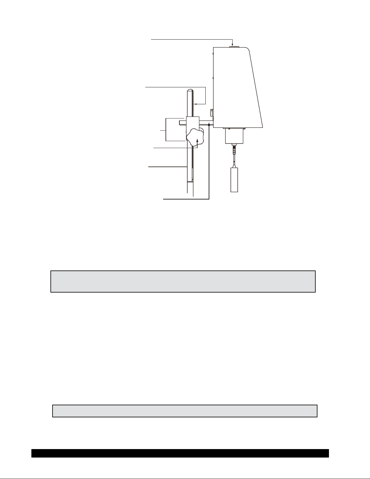
Motor
Calibrated
Spiral Spring
Drive
Shaft
Vane
Spindle
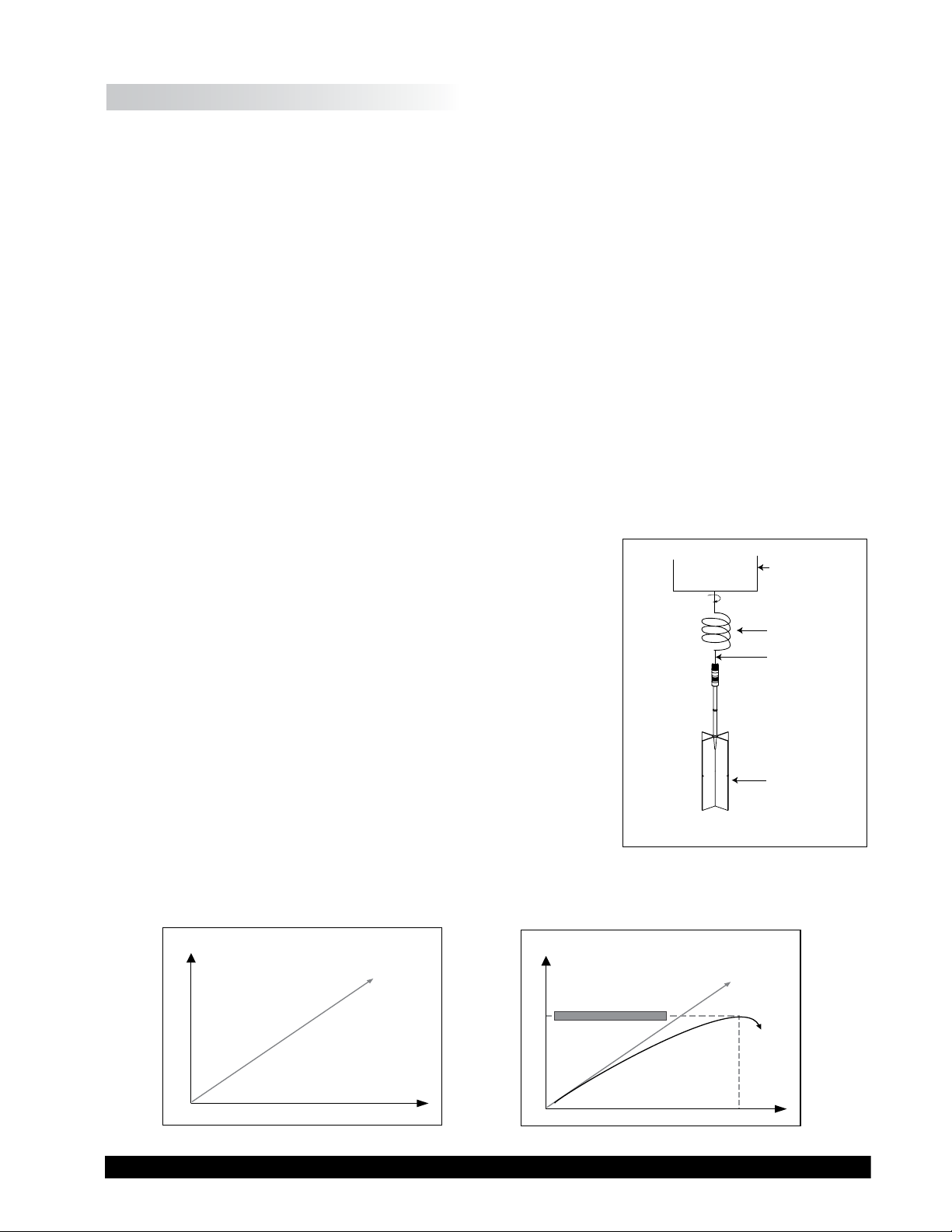
The operating principle is to drive a vane spindle through the
calibrated spiral spring connected to a motor drive shaft (see
Figure I-1). The vane spindle is immersed in the test material.
The resistance of the material to movement is measured by
observing increasing torque values as the DV-III Ultra motor
rotates. The amount of shaft rotation is measured by the deection
of the calibrated spiral spring inside the instrument. Spring
deection is measured with a rotary transducer.
If the vane spindle did not move at all, the data would look like
the graph in Figure I-2. The data often looks like the graph in
Figure I-3 because there is usually some deformation of the test
material due to the increasing force imparted by the vane spindle.
The maximum torque value is the yield point. The straight line
in Figure I-3 is a repeat of what was shown in Figure I-2. An
algorithm in the rmware converts the maximum torque value
into a yield stress value.
The shear stress measurement range of the DV-III Ultra (in Pascals) is determined by the size and
shape of the vane spindle and the full scale torque range of the calibrated spring.
Figure I-2
Maximum Torque Value
TIME
TORQUE
TIME
TORQUE
Figure I-3
Figure I-1

Brookeld Engineering Laboratories, Inc. Page 7 Manual No. M98-211-E0912
I.4 Components
Component Part Number
DV-III Ultra Rheometer depends on model
Powerbase DVP-2Y
includes:
Leveling Screws (3) VS-3
Upright Rod VS-20
Jam Nut VS-21
Clamp Assembly VS-27Y
Spindle Set with Case
LVDV-III Ultra set of four spindles or SSL
RVDV-III Ultra set of six spindles or SSR
HA/HBDV-III Ultra set of six spindles SSH
Optional Vane Set of three spindles SSVANE
For Cone/Plate versions: a spindle wrench, one cone spindle and sample cup Part No.
CPE-44Y replace the spindle set.
Power Cord
for 115 VAC DVP-65
for 230 VAC DVP-66
RTD Temperature Probe DVP-94Y
Ribbon Cable DVP-145
Guard Leg:
LVDV-III Ultra B-20Y
RVDV-III Ultra B-21Y
Carrying Case DVP-71Y
RHEOLOADER Software, EZ-Yield Software CD-PROGA
RS-232 Cable (DV-III Ultra to Computer) DVP-80
USB Cable DVP-202
Operator Manual M98-211
Please check to be sure that you have received all components, and that there is no
damage. If you are missing any parts, please notify Brookeld Engineering or your local
Brookeld agent immediately. Any shipping damage must be reported to the carrier.
Brookeld Engineering Laboratories, Inc. Page 8 Manual No. M/98-211-B0104
Brookeld Engineering Laboratories, Inc. Page 8 Manual No. M98-211-E0912
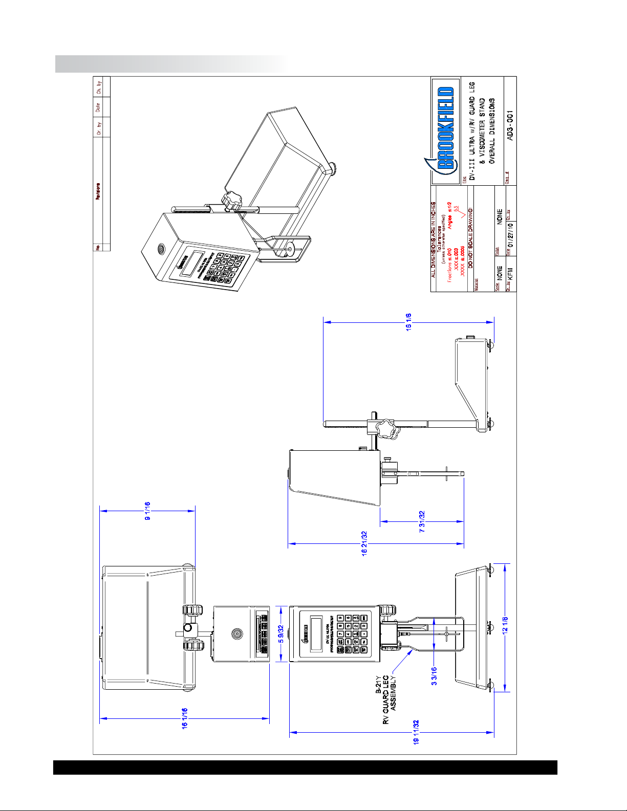
I.5 Dimensional Information

Brookeld Engineering Laboratories, Inc. Page 9 Manual No. M98-211-E0912
I.6 Utilities
Auto-sensing Power Supply:
Input Voltage: 90 - 260 VAC
Input Frequency: 50 - 60 Hz
Power Consumption: Less than 220 VA
Main supply voltage uctuations are not to exceed ± 10% of the nominal supply voltage.
Power Cord Color Code:
United States Outside United States
Hot (live) Black Brown
Neutral White Blue
Ground (earth) Green Green/Yellow
I.7 Specication
Speed Ranges 0.01-250 RPM, 0.01 RPM increments from 0.01 to 0.99 RPM,
for viscosity tests: 0.1 RPM increments from 1.0 to 250 RPM
Speed Ranges Pre Shear 0.01 to 200 rpm
for yield tests: Zero 0.01 to 0.5 rpm
Yield Test 0.01 to 5 rpm
Time Intervals 100 msec - 1000 msec
for yield tests:
Viscosity Accuracy: ± 1.0% of full scale range for a specic spindle running at a
specic speed.
Temperature sensing range: - 100°C to 300°C (-148°F to 572°F)
Temperature accuracy: ± 1.0°C from -100°C to 150°C
± 2.0°C from +150°C to 300°C
Analog Torque Output: 0 - 1 Volt DC (0 - 100% torque)
Analog Temperature Output: 0 - 4 Volts DC (10mv / °C)
Printer Output: Centronics, parallel or serial
Computer Interface: RS-232
USB
Torque Accuracy: ±1.0% of full scale range
Torque Repeatability: ±0.2%

Brookeld Engineering Laboratories, Inc. Page 10 Manual No. M/98-211-B0104
Brookeld Engineering Laboratories, Inc. Page 10 Manual No. M98-211-E0912
Operating Environment: Use indoors only.
5 °C to 40 °C temperature range (41 °F to 104 °F)
20% - 80% R.H.: non-condensing atmosphere
Pollution Degree II
Installation Category II
Altitude up to 2000 meters (max).
Weight: Gross Weight: 35 lbs. 15.9 kg
Net Weight: 32 lbs. 14.5 kg
Carton Volume: 2.0 cu. ft. 0.057 m
3
Ball Bearing Option:
If you ordered the ball bearing suspension system with your new instrument, please note the
following:
1) The ball bearing suspension in your Brookeld instrument is noted on the serial tag on
the back of the head by the letter "B" after the mode.
2) When attaching and detaching the spindle, it is not necessary to lift the coupling where
the spindle connects to the instrument.
3) The Oscillation Check explained in the Appendix J - Fault Diagnosis and Troubleshooting
does not pertain to this instrument.
Electrical Certication:
This product has been certied to the applicable CSA and ANSI/UL Standards, for use in
Canada and the U.S. (cCSAus).
Installation Category II, Pollution Degree 2, Altitude 2000m (max).
NOTICE TO CUSTOMERS:
This symbol indicates that this product is to be recycled at an appropriate collection center.
Users within the European Union:
Please contact your dealer or the local authorities in charge of waste management on how to
dispose of this product properly. All Brookeld ofces and our network of representatives
and dealers can be found on our web site: www.brookeldengineering.com
Users outside of the European Union:
Please dispose of this product according to your local laws.
Brookeld Engineering Laboratories, Inc. Page 11 Manual No. M98-211-E0912
I.8 Safety Symbols and Precautions
Safety Symbols
The following explains safety symbols which may be found in this operating manual.
Indicates hazardous voltages may be present.
Refer to the manual for specic warning or caution information to avoid personal injury
or damage to the instrument.
Precautions
If this instrument is used in a manner not specied by the manufacturer, the protection
provided by the instrument may be impaired.
This instrument is not intended for use in a potentially hazardous environment.
In case of emergency, turn off the instrument and then disconnect the electrical cord
from the wall outlet.
The user should ensure that the substances placed under test do not release poisonous,
toxic or ammable gases at the temperatures which they are subjected to during the
testing.
Instrument intended for indoor use only.
I.9 Data Retention
The DV-III Ultra will save spindle parameters (used to calculate centipoise, shear rate and shear
stress), default settings and the test data from the last program test run when the rheometer is turned
off or there is a power failure.
I.10 Set-Up
Note: "IQ,OQ,PQ", a guideline document for installation, operation and
performance validation for your DV-III Ultra Rheometer, can be
downloaded from our website: www.brookeldengineering.com
Brookeld Engineering Laboratories, Inc. Page 12 Manual No. M98-211-E0912
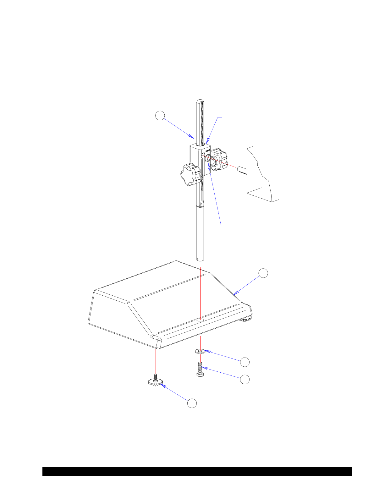
1) Place the upright rod into the hole at the front of the base. The rack gear and clamp assembly
should face the rear of the base (see Figure I-4). The upright rod (item #1) is held in place
with the jam nut (item #4) which is attached from the bottom of the base. Tighten this nut
with a suitable wrench (spanner).
DV-III Ultra Stand Assembly
CLAMP ASSEMBLY
NOTE: “FRONT” FACES TOWARD YOU.
DV-III Ultra
HEAD UNIT
TENSION SCREW
2
1
3
4
5
Figure I-4
Brookeld Engineering Laboratories, Inc. Page 13 Manual No. M/98-211-B0104
Brookeld Engineering Laboratories, Inc. Page 13 Manual No. M98-211-E0912
Bubble Level
Rack Gear
Clamp Assembly
Clamp Screw
Upright Rod
Mounting Handle
Figure I-5
2) Insert the mounting handle on the back of the DV-III Ultra into the hole on the clamp assembly
(SEE Figure I-5).
3) Tighten the DV-III Ultra clamp Screw (SEE Figure I-5).
Note: If the clamp assembly moves along the upright rod to freely, tighten the
tension screw (See Appendix G)
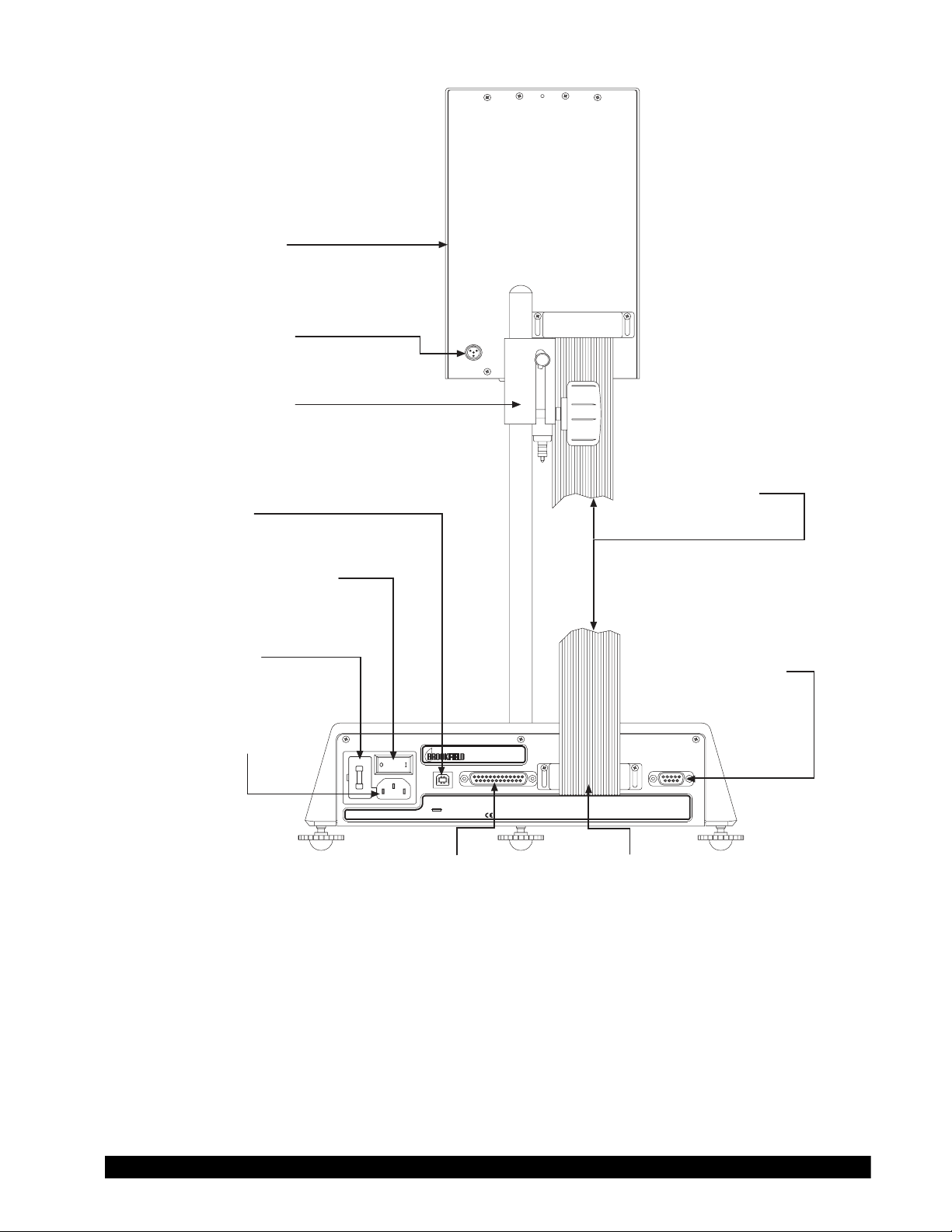
4) Insert the ribbon cable into the DV-III Ultra Rheometer head. Insert the other end of the
ribbon cable into the connector on the DV-III Ultra base (see Figure I-6).
5) Connect the RTD probe to the socket on the back side of the DV-III Ultra Rheometer (see
Figure I-6).
6) The Rheometer must be leveled before the instrument is zeroed and readings are taken. The
level is adjusted using the three leveling screws on the base. Adjust so that the bubble level
on top of the DV-III Ultra (see Figure I-5) is centered within the circle.
7) Remove the grey shipping cap which secures the lower coupling nut on the Rheometer to the
pivot cup
Note: Check level periodically during use
8) Make sure that the AC power switch at the rear of the base unit is in the OFF position. Connect
the AC plug to the socket on the back of the DV-III Ultra base and plug it into the appropriate
AC line. Allow at least 10 minutes for warm up; 30 minutes is preferable.
Brookeld Engineering Laboratories, Inc. Page 14 Manual No. M98-211-E0912
ANAL OG OUTPUT S
TORQUE 0-1V TEMP 10MV/ C
o
MODEL DV-III ULTRA BASE UNIT Rev. B
-EARTH GROUNDING REQUIRE D-
F/250V 2A
FUSE RA TINGS
US BPARALLEL PRINTE RRHEOMETER UNIT SERIAL I/O
PRINTER OR COMPUTE R
90-260V AC 50/60Hz 220V A
ELECTRIC RA TINGS (AUTORANGING)
11 COMMERCE BLVD.
MIDDLEBORO , MA 02346 U.S.A .
Rheometer Head
RTD Temperature
Probe Connector
Power ON/OFF Switch
AC Fuse(s)
AC Power Connector
Connector
Connector
Parallel Printer
Ribbon Cable
Connector
USB Cable
Ribbon Cable
Connector
RS-232 Serial
Printer/Computer
Analog Output(s)
Adjustment Knob
Figure I-6
The DV-III Ultra must be earth grounded to ensure against electronic failure!!
9) Temperature monitoring is assured (after the instrument has stabilized) to within ±1.0°C in
the range -100°C to +150°C and within 2°C in the range 150°C to 300°C.
10) For Cone/Plate models refer to Appendix A.
11) For printers, software and temperature controllers, refer to Section I.11, Connections.

Brookeld Engineering Laboratories, Inc. Page 15 Manual No. M/98-211-B0104
Brookeld Engineering Laboratories, Inc. Page 15 Manual No. M98-211-E0912
I.11 Connections
The DV-III Ultra Rheometer is capable of communicating with several external devices to enhance
operation. The cables and connections required for proper communication are detailed below.
S
RHEOLOADER
The DVP-202 USB Cable is used to connect the USB Port on the DV-III Ultra Base to the computer.
The DVP-80 cable is used to connect the RS-232 serial port on the DV-III Ultra base to Com Port
1 or Com Port 2 on the computer. Some PCs may also have Com Port 3 and Com Port 4. These
cables are supplied with the DV-III Ultra.
S
RHEOLOADER AND EZ-YIELD SOFTWARE
The DVP-80 cable is used to connect the RS-232 serial port on the DV-III Ultra base to Com Port
1 or Com Port 2 on the computer. Some PCs may also have Com Port 3 and Com Port 4. This
cable is supplied with the DV-III Ultra.
S
RHEOCALC SOFTWARE
The DVP-202 USB Cable is used to connect the USB Port on the DV-III Ultra Base to the computer.
The DVP-80 cable is used to connect the RS-232 serial port on the DV-III Ultra base to Com Port
1 or Com Port 2 on the computer. Both cables are supplied with the RHEOCALC software.
S
PARALLEL PRINTER
The CAP-86 cable is used to connect the 25-pin parallel port on the DV-III Ultra base with the
Centronics port on the printer.
S
SERIAL PRINTER
The DVP-81 cable is used to connect the 9-pin serial port on the DV-III Ultra with the 25-pin serial
port on a printer.
S
THERMOSEL CONTROLLER AND TC SERIES TEMPERATURE BATHS
Earlier model baths with programmable Brookeld Controllers will also work.
The DVP-141 cable is used to connect the serial port on the DV-III Ultra base to the serial port on
the controller. This cable is supplied with the controller/bath.
Be sure that the controller temperature probe is properly located in the control device (Thermosel
or bath) and connected to the controller.
Note: 1. The controller may alternately communicate with Rheocalc V.2.0 or
higher software. In this conguration, the controller is connected to the
computer through either Com Port 1 or Com Port 2 by using the DVP-80
cable. The DV-III Ultra can also be connected to a computer through
the USB Port by using the DVP-202 cable.
2. The controller must also be connected to the control device (Thermosel
or bath) with the appropriate load cable.
Brookeld Engineering Laboratories, Inc. Page 16 Manual No. M98-211-E0912
S STRIP CHART RECORDER
DVP-96Y cable is used to connect the serial port on the DV-III Ultra to the input block of the strip
chart recorder. This cable is supplied with a Brookeld strip chart recorder.
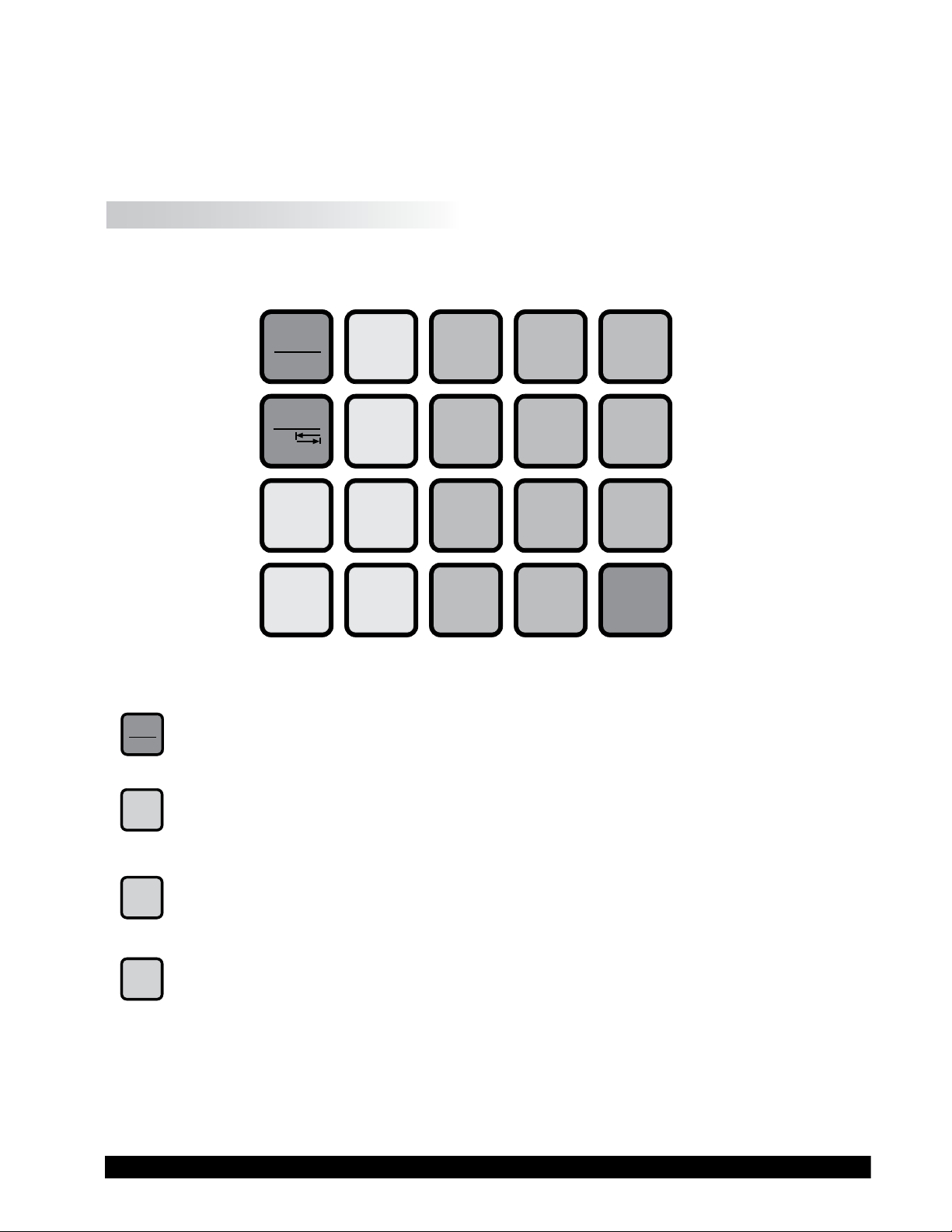
I.12 Key Functions
Figure I-7 shows the control keys on the face of the DV-III Ultra Rheometer. The following describes
each key’s function.
OPTION
TAB
ENTER
YES NO
SELECT
DISP
PRINT
1
789
456
3
2
0
.
SELECT
SPDL
PROG
RUN
MOTOR
ON/OFF
ESCAPE
PROG
AUTO
RANGE
Figure I-7
MOTOR
ON/OFF
ESCAPE
MOTOR ON/OFF, ESCAPE
Turns the motor on or off. Cancels any operation. Returns the user to the previous screen.
AUTO
RANGE
AUTORANGE
Presents the maximum (100% torque) viscosity attainable using the selected spindle at
the current speed.
SELECT
SPDL
SELECT SPDL
Allows selection of the spindle to be used.
SELECT
DISP
SELECT DISP
Selects the parameter to be displayed:
% Rheometer Torque (%)
cP Viscosity (cP or mPa
.
s)
SS Shear Stress (Dynes/cm
2
or Newtons/m
2
)
SR Shear Rate (1/Sec)
Brookeld Engineering Laboratories, Inc. Page 17 Manual No. M/98-211-B0104
Brookeld Engineering Laboratories, Inc. Page 17 Manual No. M98-211-E0912
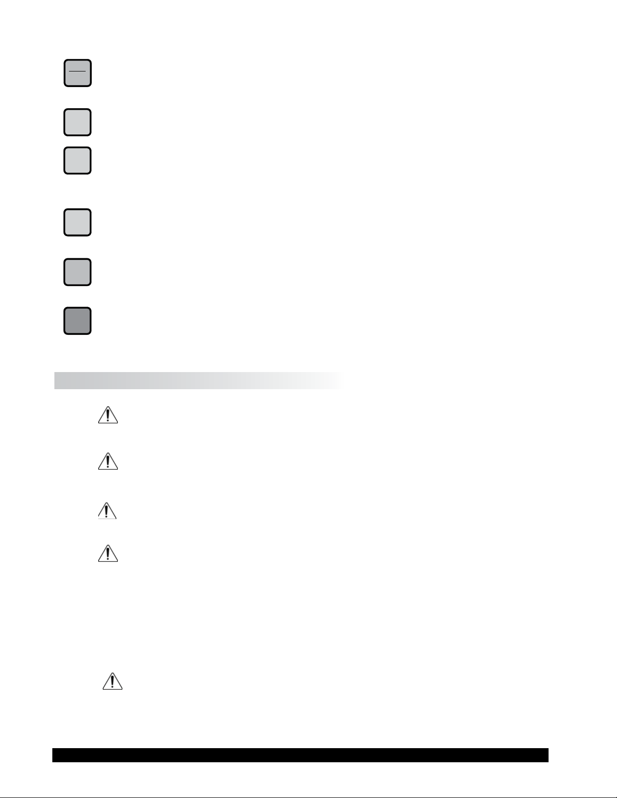
OPTION
TAB F
OPTION, TAB
Accesses options menu (see Section V). Toggles between selectable items when indicated.
PRINT
PRINT
Sends a single line of data to an attached printer. Selects printing and non-printing mode as
selected in the Options menu.
PROG
PROG
Access the Programs menu for program creation, running or deleting. Constructs a test program.
Allows you to review/modify an existing test program. Execute a Bevis program.
PROG
RUN
PROG RUN
Execute DV-III Ultra speed/time pair program.
NUMBER KEYS (0 through 9)
0
Sets speeds and choose items from various dialog screens and the option menu.
ENTER
ENTER
Functions as an ENTER key similar to a computer by serving to accept a keyboard entry.
I.13 Cleaning
Make sure the instrument is in a decent working environment (dust-free, moderate
temperature, low humidity, etc).
Make sure the instrument is on a level surface.
Hands/ngers must be clean and free of residual sample. Not doing so may result in
deposit build-up on the upper part of the shaft and cause interferences between the
shaft and the pivot cup.
Be sure to remove the spindle from the instrument prior to cleaning. Severe
instrument damage may result if the spindle is cleaned in place.
Instrument and Keypad: Clean with a dry, non-abrasive cloth. Do not use solvents
or cleaners.
Immersed Components (spindles): Spindles are made of stainless steel. Clean with a
non-abrasive cloth and solvent appropriate for sample
material.
When cleaning, do not apply excessive force which may result in bending the
spindles.

Brookeld Engineering Laboratories, Inc. Page 18 Manual No. M98-211-E0912
II. GETTING STARTED
II.1 Autozero
Before readings may be taken, the Rheometer must be auto zeroed. This is done each time the
power switch is turned on. The Rheometer will guide you through the procedure, as follows:
Turn power switch on; as shown in Figure II-1, the screen indicates that the DV-III Ultra is in the
standalone mode (is not connected to a computer) and gives the version of the operating rmware
(the built in program which controls the instrument) and a two-digit alphanumeric code which
indicates the Model number (see Table D2 in Appendix D; the code tells the spring torque rating
of your Rheometer).
BROOKFIELD
DV-III ULTRA RHEOMETER
V1.0 HA
STANDALONE
Figure II-1
No key press is necessary. After a short pause the display will read “REMOVE SPINDLE, LEVEL
RHEOMETER AND PRESS THE MOTOR ON/OFF KEY TO AUTOZERO.” Before beginning the autozero
procedure, Brookeld recommends that you allow 10 minutes for the instrument to warm up.
After pressing the MOTOR ON/OFF key, the screen “ashes” for approximately 15 seconds while
the DV-III Ultra auto zeros.
After 15 seconds the display reads “AUTOZERO IS COMPLETE REPLACE SPINDLE AND PRESS ANY
KEY.” Press a key.
The main screen is displayed and the DV-III Ultra is ready for use (Figure II-2).
RPM: 0.0 SPINDLE: 31
TEMP: 72.1 F PRTN
TORQUE = 0.0 %
Figure II-2
II.2 Rheometer Display
The DV-III Ultra Rheometer is supplied with a 4-line display. The basic set of information is called
"The Default Screen" and is shown in Figure II-3. The parameters are detailed below:
RPM: 0.0 SPINDLE: 31
TEMP: 72.1°F PRTN
TORQUE = 0.0 %
Figure II-3

Brookeld Engineering Laboratories, Inc. Page 19 Manual No. M/98-211-B0104
Brookeld Engineering Laboratories, Inc. Page 19 Manual No. M98-211-E0912
1. Motor Status and Current Rheometer Speed
The DV-III Ultra motor can be OFF, ON at 0.0 rpm or ON at a speed greater than 0.0 rpm.
When the motor is OFF, "OFF" will be displayed and no speed entry will be accepted. When
the motor is ON, the actual speed of rotation will be displayed. When the motor is switched
from ON to OFF, the speed of rotation will be remembered; when the motor is turned ON
again, the DV-III Ultra will operate at that same speed. The rheometer motor is set to "OFF"
after AUTOZERO.
Note: Motor OFF and a speed setting of 0.0 are essentially the same.
2. Spindle Number
The currently-selected spindle. Viscosity, shear rate, and shear stress values will be calculated
based on this number. See Section II.3.
3. Measured Temperature
The current temperature as measured by the attached temperature probe. If no probe is
connected, four dashes "----" will be displayed.
4. Printing Status
Indicates the currently-selected method of printing.
5. Measured Data
Instrument Torque (%), Viscosity (cP), Shear Stress (D/cm2), Shear Rate (s
-1
)
The parameters are toggled from one to another using the Select Display key.
Note: Shear Stress and Shear Rate data cannot be calculated for some spindle
geometries. In these cases, the display will show 0.0.
6. Blank Line
This line is used to display entry data when selecting a spindle or speed of rotation. Additionally,
selected programs available for running will be identied here when in the Program mode.
(See Section IV.2).
The default screen will appear at the completion of the AUTOZERO sequence each time the DV-III
Ultra is turned ON in the standalone mode (see Section II.5: External Control). The displayed data
may be changed as described in the following sections.
The format for data displayed in the default screen and all other screens is described in Table 11.1.
For appearance sake, the entries in the table have been decimal point aligned. Actual rheometer
display will have all elds left justied.

Brookeld Engineering Laboratories, Inc. Page 20 Manual No. M98-211-E0912
ITEM PRINT FORMAT RANGE EXAMPLE
RPM RPM
X.XX
XX.X
XXX.X
0.01 <= RPM <= 0.99
0.1 <= RPM <= 99.9
100 <= RPM <= 250
0.09
2.4
150.0
Model M
XXXXX
See Model Table D-2 - Appendix D RV
Spindle S
XX
00 <= S <= 99 31
Torque T
XX.X
-10.1 <= T <= 99.9 82.4
Viscosity cP or mPas
X.XX
XXX.X
XXXXX
XXXeX
0 <= cP <= 9.99
10 <= cP <= 999.9
1000 <= cP <= 99999
100000 <= cP <=
51200000000
3.16
123.8
12345
123e3 to 8
Shear Stress D/CM2 or
N/M2 =
D/CM 2/10
X.XX
XXX.X
XXXXX
XXXeX
0 <= D/CM2 <= 9.99
10 <= D/CM2 <= 999.9
1000 <= D/CM2 <= 99999
100000 <= D/CM2 <= 999999
4.56
234.5
12345
123e3
Shear Rate 1/SEC
X.XXX
XX.X
XXXXX
0 <= 1/SEC <= 9.999
10 <= 1/SEC <=99.9
100 <= 1/SEC <= 99999
1.234
20.7
200
Temperature T
-99.9 <= T <= 300.0 -10.3
Time Z
XX:XX
00:00 <= Z <= 99.59 05:32
Table II-1
S
OUT OF RANGE INDICATORS
The DV-III Ultra is capable of measuring instrument torque within the range of 0 to 100%. Based
on this measurement, viscosity and shear stress are calculated. Brookeld recommends that data be
collected only in the range of 10 to 100%. Any data collected outside of this range is considered
invalid.
The DV-III Ultra provides the following display indicators when the measurement point is outside
of the 10-100% acceptable range.
S TORQUE GREATER THAN 100%
When Rheometer torque exceeds 100%, the parameter display eld will show “EEEE” for torque,
viscosity and shear stress.
RPM: 112 SPINDLE: 31
TEMP: 72.1°F PRTN
TORQUE = EEEE %
Figure II-4
S TORQUE LESS THAN 10%
When Rheometer torque drops below ten (10) percent, the Rheometer will continue to display
measurement (%, cP, D/cm
2
) values with units ashing:

Brookeld Engineering Laboratories, Inc. Page 21 Manual No. M/98-211-B0104
Brookeld Engineering Laboratories, Inc. Page 21 Manual No. M98-211-E0912
RPM: 112 SPINDLE: 31
TEMP: 72.1°F PRTN
VISC = 900@6 CPS
Figure II-5
S TORQUE LESS THAN 0%
When Rheometer torque drops below zero (0) percent, the Rheometer will continue to display
torque values preceded by a minus (-) sign. The viscosity and shear stress eld will display dashes
(- - - - ) as indicated in Figure II-6:
RPM: 112 SPINDLE: 31
TEMP: 72.1°F PRTN
S STR = ----- D/CM2
Figure II-6
II.3 Spindle Entry
The user can elect to change the spindle selection by pressing the
SELECT SPDL key. The DV-III
Ultra control program will use the previously blank line 3 on the default display screen to record
the new spindle input as depicted in Figure II-7.
RPM: 0.0 SPINDLE: 31
TEMP: 72.1°F PRTN
ENTER SPINDLE # 31
TORQUE = 0.0%
Figure II-7
To enter a spindle number, press the numeric keys until the desired spindle number has been entered.
Valid spindle numbers encompass the range from 00 to 99 as listed in Appendix D. Mistakes are
corrected by repeatedly pressing the numeric keys until the proper spindle value has been entered.
At that point, the user presses the
SELECT SPDL key again. An invalid spindle entry will result in a
“beep” and the display of the data entry error screen as shown in Figure II-8.
INVALID DATA ENTRY
"BAD SPINDLE"
** RE-ENTER **
Figure II-8
An invalid spindle entry is any two digit number in the range from 01 to 99 which is not listed in
Appendix D. This error message will be displayed for a few seconds after which the spindle entry
screen (see Figure II-7) will be re-displayed with a blank eld for the spindle number. The user
can cancel spindle entry at any time by pressing the
MOTOR ON/OFF/ESCAPE key.
To enter a new spindle into memory, use the following procedures.
Press and Hold the motor on/off and “9” key on power up. The screen in Figure II-9 appears.
Brookeld Engineering Laboratories, Inc. Page 22 Manual No. M98-211-E0912
VISCOMETER SETUP
PRESS ENTER TO START
Figure II-9
Press the
ENTER key. The screen in Figure II-10 appears. Press the "3" key for NO.
PRINT PARAM RAM?
1 = YES 3 = NO
Figure II-10
The display will now ask “SPECIAL SPINDLE?” as shown in Figure II-11. Press the “1” key
for YES.
SPECIAL SPINDLE?
1 = YES 3 = NO
Figure II-11
The display will ask “ADD A SPINDLE?” Press the “1” key for YES.
ADD A SPINDLE?
1 = YES 3 = NO
Figure II-12
The spindle number and name will be ashing. Use the “2” key for scrolling downward (ê) and
the “8” key for scrolling upward (è). The spindle name can be changed to any (2) letters from A
to Z.
Use the “tab” key to move left and right through the menu. Press the “enter” key to accept.
SPECIAL SPINDLE #1
NAME = D AA E
SMC =
SRC =
Figure II-13
Check the spindle constants to be entered. You must have the SMC (spindle multiplier constant)
and the SRC (the shear rate constant). Enter the rst set of numbers. Press the “enter” key to go
to the next line (example: spindle AA = SMC = 1.0 SRC = 2.0).
If you are adding additional spindles, press the “enter” key. You can enter up to 5 special
spindles.
Brookeld Engineering Laboratories, Inc. Page 23 Manual No. M/98-211-B0104
Brookeld Engineering Laboratories, Inc. Page 23 Manual No. M98-211-E0912
SPECIAL SPINDLE #2
NAME = D BB E
SMC = 1.000
SRC = 2.000
Figure II-14
To complete, enter 0 values for SMC and SRC.
The display may ask “ADD A SPINDLE”. You may press YES to repeat or NO to nish.
ADD A SPINDLE?
1 = YES 3 = NO
Figure II-15
If you press “3” NO, the display will ask “SAVE NEW SPINDLE?” Press the “1” YES to save or
press “3” NO.
SAVE NEW SPINDLES?
1 = YES 3 = NO
Figure II-16
The display will now say “SET UP COMPLETE”, turn power off.
You can edit any existing spindle entry names and spindle constants. If so, you will need to complete
the steps until you are prompted to “Save New Spindle”. For example, if you have three special
spindles entered and need to modify the second spindle, you will need to proceed through the third
spindle parameters by pressing “Enter” until prompted to “Save New Spindle”. This will then save
the modied spindle.
II.4 Direct Speed Entry
At this point, the user may choose to enter a speed by the so-called direct speed entry method.
Enter a valid speed in the range of 0.01 to 250 RPM by pressing the numeric keys successively.
The previously blank line 3 on the default display screen records the user’s new speed input as
depicted in Figure II-17:
RPM: 0.0 SPINDLE: 31
TEMP: 72.1°F PRTN
ENTER NEW RPM: 11_
TORQUE = 0.0 %
Figure II-17
Here, the user intends to enter a speed of 112 RPM, has pressed the “1” key twice and is about
to press the “2” key. If the user makes more than ve (5) key presses, the DV-III Ultra control
program will “roll” the cursor back to the rst character of the eld and begin to overwrite the
previous data entry.
Next the user presses the
ENTER key to accept the speed. The motor will begin running at 112 RPM
Brookeld Engineering Laboratories, Inc. Page 24 Manual No. M98-211-E0912
and the display will be updated to the next screen image:
RPM: 112 SPINDLE: 31
TEMP: 72.1°F PRTN
TORQUE = 56.3 %
Figure II-18
If the speed entered was not valid the Rheometer will display the following message:
INVALID DATA ENTRY
"BAD SPEED/TIME"
** RE-ENTER **
Figure II-19
After a few seconds, the display returns to Figure II-17 with the speed data eld cleared and just
the underscore cursor awaiting a new entry.
II.5 External Control
The DV-III Ultra Rheometer can be used in conjunction with Brookeld software, RHEOCALC
(V. 2. or higher). Through RHEOCALC, all rheometer functions are controlled by the computer.
The DV-III Ultra must be set to the external control mode to allow for proper communication with
RHEOCALC. To congure the external control mode, connect computer interface cable DVP-80
(RS-232) or DVP-202 (USB) to the port on the DV-III Ultra base before turning on the DV-III
Ultra. With the DVP-80 cable in place, the DV-III Ultra will present the screen shown in Figure
II-20 when it is turned on. If external control is selected, the DV-III Ultra will display Figure II-21
and only accept control commands from RHEOCALC software.
BROOKFIELD
DV-III ULTRA RHEOMETER
1 = EXTERNAL CONTROL
2 = STANDALONE MODE
Figure II-20
BROOKFIELD
DV-III ULTRA RHEOMETER
V0.0 HA
EXTERNAL
Figure II-21
The DV-III Ultra may be set to stand alone mode by turning it OFF and ON again and selecting
"Stand Alone" or by removing the cable (DVP-80 or DVP-202) prior to turning the DV-III Ultra
on.
Note: The DV-III Ultra cannot communicate with RHEOLOADER or EZ-
Yield software in the external control mode. Choose "Stand Alone"
when presented with Figure II-20 if you want to use RHEOLOADER
or EZ-YIELD.

Brookeld Engineering Laboratories, Inc. Page 25 Manual No. M98-211-E0912
II.6 Preventative Maintenance
The DV-III Ultra does not require any internal maintenance or adjustment. Periodic verication
of calibration is an important procedure. We recommend that you check the calibration of
your DV-III Ultra on a regular basis. The frequency of calibration checks should be set based
on your use of the instrument and the signicance of the data. We generally recommend
a frequency of 1 month. See Appendix E - Calibration Check Procedure for information on
performing a calibration check.
Any condition that results in an out of calibration result (see Interpretation of Calibration
Results at the end of Appendix E) must be corrected by Brookeld or our authorized dealers.
Please check our web site for information on our dealers and a Laboratory Return Form;
www.brookeldengineering.com.
Preventative maintenance for the DV-III Ultra consists primarily of good practice when
using the instrument. Please follow the suggestions below.
• Long term storage: When the DV-III Ultra will be out of service for an extended period
of time, use the Instrument Carrying Case in which it was supplied. Be sure to install
the shipping cap.
• When the unit is not in use, place it on the back of the laboratory bench out of the
way of normal activity.
• Be sure that the unit is properly leveled for all measurements (Section I.10; Step 6).
• Periodically check the Tension Screw on the Clamp Assembly of the Upright Rod
Assembly (Appendix G). This screw should be tight enough to prevent the unit from
moving down the rod spontaneously but not so tight as to prevent the operator
from moving the unit with the adjustment knob.
• Keep hands free from test materials to prevent transfer of material to surfaces of
the unit.
• Keep the bottom of the unit housing clean from test samples and debris. The pivot
cup and spindle connection should be clean and free of any material. This will ensure
proper connection of the spindle to the unit and proper rotation of the spindle
(minimize run out).
• Properly clean spindles and sample chambers (optional) after each measurement.
Remove the spindle from the unit prior to cleaning, not doing so may result in the
spindle being bent. Use cleaning solvents that are compatible with 300 series
stainless steel. Do not use abrasive cloths.
• Clean keypad and display screen with a soft dry cloth. Do not use harsh solvents or
abrasive materials.
• Clean instrument surfaces with a soft dry cloth. Solvents may remove factory
paint.
• Wells/Brookeld cone spindles should be handled carefully to prevent scratches to
the measurement surface and nicks on the outer radius. Do not drop the spindle
on the lab bench or oor. We recommend placing a rubber mat in the areas around
the DV-III Ultra when these spindles are in use.

Brookeld Engineering Laboratories, Inc. Page 26 Manual No. M98-211-E0912
• Wells/Brookeld sample cups should be handled carefully to prevent scratches or
nicks. Do not use abrasive cleaners or cloths.
• Store all spindles in the protective case in which they were supplied.
• Do not store spindles attached to the unit.
• Periodically inspect all cables for proper connection and damage.

Brookeld Engineering Laboratories, Inc. Page 27 Manual No. M/98-211-B0104
Brookeld Engineering Laboratories, Inc. Page 27 Manual No. M98-211-E0912
III. MAKING VISCOSITY AND YEILD MEASUREMENTS
III.1 Quick Start
Viscosity Measurement
The DV-III Ultra Rheometer uses the same methodology for viscosity measurement as the Brookeld
Dial Reading Viscometer and DV series of Digital Viscometers. If you have experience with other
Brookeld equipment, this section will give you the quick steps for taking a viscosity reading. If
you have not used a Brookeld Viscometer before, skip this section and go to Section III.2 for a
detailed description.
A) Assemble and level the rheometer (Section I.10).
B) Turn power on. Select 2 = STANDALONE MODE.
C) Autozero the rheometer (Section II.1).
D) Enter the spindle number using the SELECT SPINDLE key (Section II.3).
E) Introduce the spindle into the sample and attach the spindle to the coupling nut.
NOTE: Left-hand threads.
F) Enter the speed of rotation using the number pad and ENTER key (Section II.4).
G) Record % torque and viscosity.
Yield Measurement
The DV-III Ultra Rheometer uses the same methodology for yield measurement as the Brookeld
YR-1 Rheometer. If you have experience with the YR-1, this section will give you the quick steps
for taking a yield stress reading. If you have not used a Brookeld Viscometer before, skip this
section and go to Section IV.8 for a detailed description.
A) Assemble and level the rheometer (Section I.10).
B) Turn power on. Select 2 = STANDALONE MODE.
C) Autozero the rheometer (Section II.1).
D) Press the PROG key on the rheometer keypad. The rheometer will display the “PROGRAM
MODES” screen as shown in Figure II.20. Press the “4” key to access the Yield Program.
E) Start the EZ-Yield software program on your PC. In the upper right corner of the main screen,
set the instrument setting to “DV-III ULTRA” and the COM port setting to the appropriate
com port.
F) Click on the “Test Parameters” tab beneath the toolbar on your PC screen. Insert values for
the EZ-Yield test parameters as explained in Section I.3 and save the le if required for future
use.
G) Click the download button on the toolbar on your PC screen. The screen on the rheometer
will show “DOWNLOAD COMPLETE, PRESS ANY KEY”.

Brookeld Engineering Laboratories, Inc. Page 28 Manual No. M98-211-E0912
H) Press the ENTER button on the rheometer to run the test. The screen will then show “USE
SPINDLE #__”. Conrm that the correct spindle is attached to the rheometer and that the
sample is properly prepared and in position to begin the test. Press the ENTER button to start
the test.
I) After a few seconds, your PC will automatically show the Graphs page in the EZ-Yield software
program, indicating that the test has begun. The DV-III Ultra will send data to the PC and the
graph of the yield stress ow behavior will be captured. The Data page in the software will
record the actual numerical values for shear stress.
J) When the test is complete, a dialog box appears asking you to save the data that was just
acquired.
K) Subsequent tests can be started by either pushing the ENTER button on the DV-III Ultra or
by clicking the RUN button in the EZ-Yield software.
III.2 Preparations for Making Measurements
A) RHEOMETER: The DV-III Ultra should be turned on, leveled and auto zeroed. The level is
adjusted using the three feet on the bottom of the base and conrmed using the bubble on the
top of the head. Adjust the feet until bubble is inside the center target. Set the level prior to
autozero and check the level prior to each measurement.
Proper level is essential for correct operation of the DV-III Ultra.
B) SAMPLE: The uid to be measured (sample) must be in a container. The standard spindles
supplied with the DV-III Ultra (LV (1-4), RV (2-7), or HA/HB (2-7)) are designed to be used
with a 600 ml low form Grifn beaker (or equivalent container with a diameter of 8.25cm).
The same applies to the optional RV1, HA/HB1, and Vane spindles. Many other spindle
systems are supplied from Brookeld with specic sample chambers such as the Small Sample
Adapter, UL Adapter and Thermosel.
Brookeld recommends that you use the appropriate container for the selected spindle. You
may choose to use an alternate container for convenience, however, this may have an effect
on the measured viscosity. The DV-III Ultra is calibrated considering the specied container.
Alternate containers will provide results that are repeatable but not "true."
The LV (1-4) and RV (1-7) are designed to be used with the guardleg attached (see Appendix
F). Measurements made without the guardleg will provide repeatable results but may not
provide "true" results.
When comparing data with others, be sure to specify the sample container and presence/
absence of the guardleg.
Many samples must be controlled to a specic temperature for viscosity measurement. When
conditioning a sample for temperature, be sure to temperature control the container and spindle
as well as the sample.
Please see our publication, "More Solutions to Sticky Problems", for more detail relating to
sample preparation.
C) SPINDLE ATTACHMENT: The method of spindle connection to the DV-III Ultra is specied
at the time of order as either Standard Threaded Shaft or EZ-Lock. The spindle connection
method may be changed by sending the DV-III Ultra to Brookeld or our authorized agents.
There is an adapter available to convert Standard Threaded Spindles to EZ-Lock Spindles. It
is not possible to use EZ-Lock Spindles on a Standard Threaded Unit.
Brookeld Engineering Laboratories, Inc. Page 29 Manual No. M/98-211-B0104
Brookeld Engineering Laboratories, Inc. Page 29 Manual No. M98-211-E0912
Note: If you are using an accessory device such as a Small Sample Adapter,
the complete kit must be congured for the EZ-Lock Unit to ensure
proper alignment and spindle immersion. Contact Brookeld for more
information.
Figures III-1a and III-1b shows the method for both connection systems.
Figure III-1a: EZ-Lock Figure III-1b: Standard Spindle
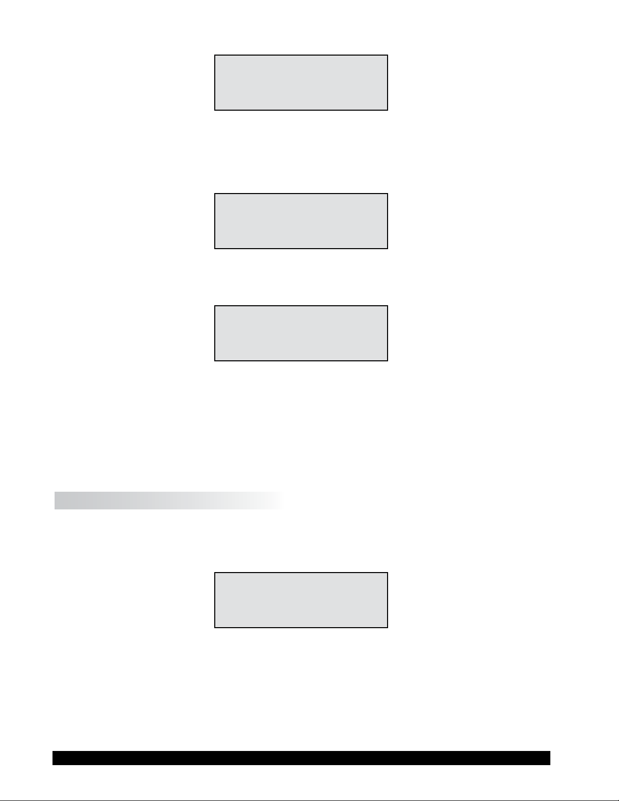
Standard Threaded Shaft
The spindles are attached to the viscometer by screwing them onto the lower shaft. Note that the
spindles have a left-handed thread. The lower shaft should be secured and slightly lifted with one
hand while screwing the spindle to the left. The face of the spindle nut and the matching surface
on the lower shaft should be smooth and clean to prevent eccentric rotation of the spindle. Spindles
can be identied by the number on the side of the spindle coupling nut.
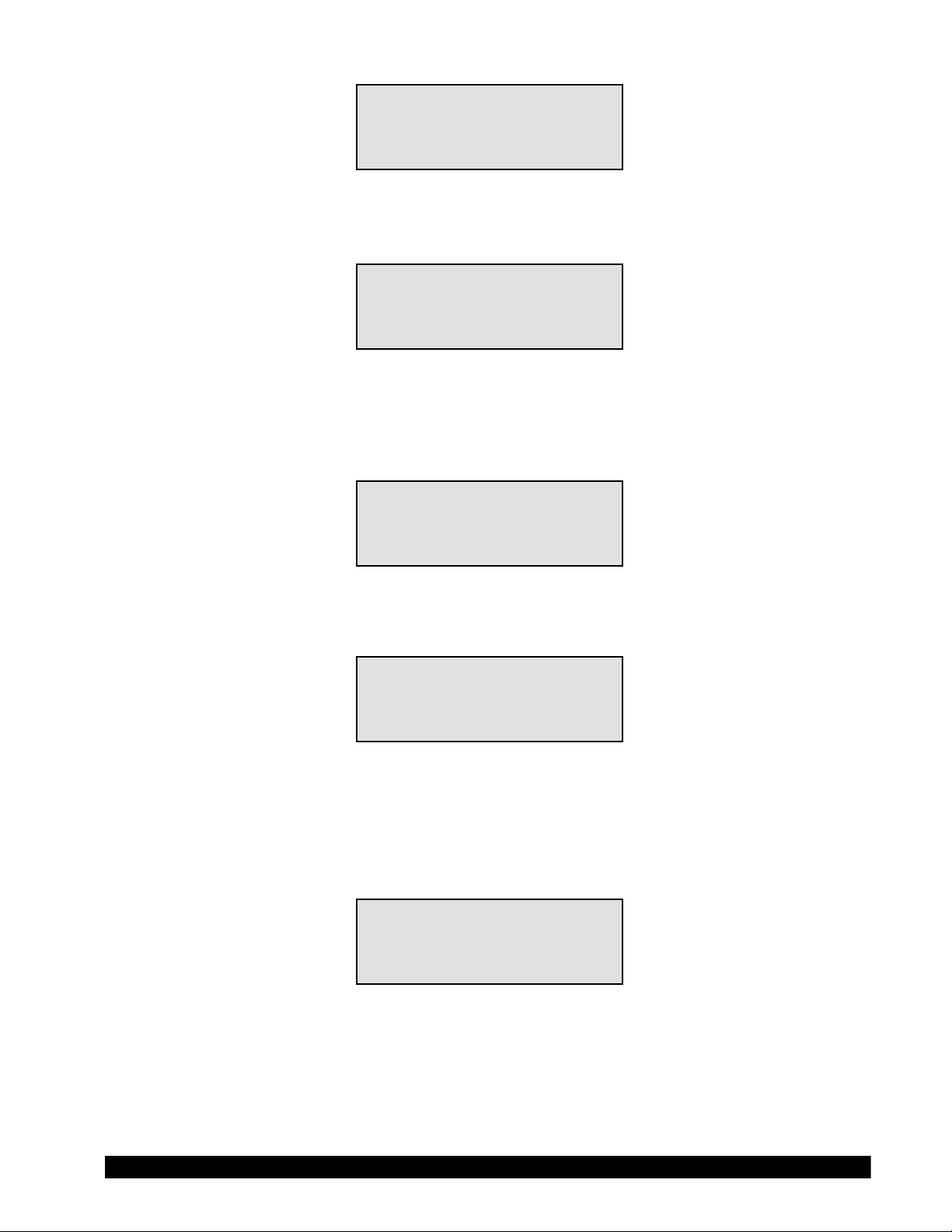
EZ-Lock
Hold the spindle with one hand while gently raising the spring-loaded outer sleeve to its highest
position with the other hand. Insert the EZ-Lock Spindle Coupling so that the bottom of the coupling
is ush with the bottom of the sleeve, and lower the sleeve. The sleeve should easily slide back
down to hold the spindle/coupling assembly in place for use. [Spindles can be identied by entry
code; look for the number on the side of the EZ-Lock spindle coupling.]

Brookeld Engineering Laboratories, Inc. Page 30 Manual No. M98-211-E0912
III.3 Selecting a Spindle/Speed
The DV-III Ultra has the capability of measuring viscosity over an extremely wide range (for example,
the RVDV-III Ultra can measure uids within the range of 100-40,000,000 cP) (see Appendix B).
This range is achieved through the use of several spindles over many speeds. When measuring
yield stress with vane spindles, a broad measurement range is also possible through the choice of
multiple spindles.
The process of selecting a spindle and speed for an unknown uid is normally trial and error. An
appropriate selection will result in measurements made between 10-100 on the instrument %
torque scale. Two general rules will help in the trial and error process.
1) Viscosity range is inversely proportional to the size of the spindle.
2) Viscosity range is inversely proportional to the rotational speed.
In other words: to measure high viscosity, choose a small spindle and/or a slow speed. If the chosen
spindle/speed results in a reading above 100%, then reduce the speed or choose a smaller spindle.
Experimentation may reveal that several spindle/speed combinations will produce satisfactory results
between 10-100%. When this circumstance occurs, any of the spindles may be selected.
Non-Newtonian uid behavior can result in the measured viscosity and yield stress changing if the
spindle and/or speed is changed. See our publication, "More Solutions to Sticky Problems," for
more detail.
When viscosity and/or yield stress data must be compared, be sure to use the same test
methodology: namely the same instrument, spindle, speed, container, temperature and test
time.
III.4 Multiple Data Points
The majority of viscosity and yield stress measurements are made at the quality control level and
often consist of a single data point. The test is conducted with one spindle at one speed. The data
point is a useful bench mark for the go/no-go decision in a production setting. The DV-III Ultra
can be used for single point measurement.
Many uids exhibit a characteristic change in viscosity and yield stress with a change in applied
force. This non-Newtonian ow behavior is commonly seen in paints, coatings and food products
as a decrease in viscosity as shear rate increases or an increase in yield stress as rotational speed
increases. This behavior cannot be detected or evaluated with the single point measurement.
Non-Newtonian ow is analyzed through the collection of viscosity data over a range of shear
rates and the generation of a graph of viscosity versus shear rate (a rheogram). The same applies to
yield stress determination by analyzing torque vs. time behavior at different rotational speeds. This
information will allow for a more complete characterization of a uid and may help in formulating
and production of the product. The DV-III Ultra is capable of collecting multiple data points for
comprehensive analysis of ow behavior. See Section IV on Programming and Analysis.
More information on ow behavior, shear rate and rheograms is available in our publication, "More
Solutions to Sticky Problems."
 Loading...