


Broan BCSD124SS, BCSD130WW, BCSD142WW, BCSD136WW, BCSD136SS Owner’s Manual
...WWW.BROAN.COM
RANGE HOOD
Series: BCSD
INSTALLATION, USE
AND CARE MANUAL
Serial number: 
99045652-102G

MANUAL |
OF CONTENTS |
INSTALLATION |
TABLE |
2
Safety . . . . . . . . . . . . . . . . . . . . . . . . . . . . . . . . . 3-4
Operation . . . . . . . . . . . . . . . . . . . . . . . . . . . . . . . 5
Cleaning and Maintenance . . . . . . . . . . . . . . . . . 6
Motor
Grease Filters
Non-Ducted Recirculation Filters
Fan Blade
Stainless Steel Cleaning
Painted Finish Cleaning
Installation . . . . . . . . . . . . . . . . . . . . . . . . . . . . 7-20
Recommended Tools
and Accessories for Installation . . . . . . . . . . . . 7 Install Ductwork (Ducted Installations Only) . . . 7
Contents . . . . . . . . . . . . . . . . . . . . . . . . . . . . . . 8 Prepare the Hood . . . . . . . . . . . . . . . . . . . . . . . 9-11 Prepare the Hood Location . . . . . . . . . . . . . . . . 12
EZ1 One-person Installation . . . . . . . . . . . . . 12-14 Install the Hood (EZ1 Bracket). . . . . . . . . . . . 15-16
Standard Installation . . . . . . . . . . . . . . . . . . . 17 Install the Hood (Standard Installation) . . . . . 18 Connect the Wiring . . . . . . . . . . . . . . . . . . . . . . 19
Install the Light Bulbs . . . . . . . . . . . . . . . . . . . . 20 Install the Filters . . . . . . . . . . . . . . . . . . . . . . . . 20
Wiring Diagram . . . . . . . . . . . . . . . . . . . . . . . . . 21
Service Parts . . . . . . . . . . . . . . . . . . . . . . . . . 22-25
Warranty . . . . . . . . . . . . . . . . . . . . . . . . . . . . . . . 26
READ AND SAVE THESE INSTRUCTIONS
 !
!  Intended for domestic cooking only
  !
! 
INSTALLER: LEAVE THIS MANUAL WITH HOMEOWNER.
Register your range hood online at www.broan.com
 !
!  WARNING
TO REDUCE THE RISK OF FIRE, ELECTRIC SHOCK, OR INJURY TO PERSONS, OBSERVE THE FOLLOWING:
• Use this unit only in the manner intended by the manufacturer. If you have questions, contact the manufacturer at the address or telephone number listed in the warranty.
•Before servicing or cleaning unit, switch power off at service panel and lock the service disconnecting means to prevent power from being
switched on accidentally. When the service disconnecting means cannot be locked, securely fasten a prominent warning device, such as a tag, to the service panel.
•Installation work and electrical wiring must be done by a qualified person(s) in accordance with all applicable codes and standards, including fire-rated construction.
•Sufficient air is needed for proper combustion and exhausting of gases through the flue (chimney) of fuel burning equipment to prevent
backdrafting. Follow the heating equipment manufacturer’s guidelines and safety standards such as those published by the National Fire Protection Association (NFPA) and the American Society for Heating, Refrigeration and Air Conditioning Engineers (ASHRAE) and the local code authorities.
•When cutting or drilling into wall or ceiling, do not damage electrical wiring and other hidden utilities.
•Ducted fans must always be vented to the outdoors.
•Do not use this unit with any additional solid-state speed control device.
•To reduce the risk of fire, use only metal ductwork.
•This unit must be grounded.
•As an alternative, this product may be installed with the UL-approved cord kit designated for the product, following instructions packed with the cord kit.
•When applicable local regulations comprise more restrictive installation and/or certification requirements, the aforementioned requirements prevail on those of this document and the installer agrees to conform to these at his own expense.
SAFETY |
MANUAL INSTALLATION |
3
INSTALLATION MANUAL |
SAFETY |
4
 !
!  WARNING
TO REDUCE THE RISK OF A RANGE TOP GREASE FIRE:
a)Never leave surface units unattended at high settings. Boilovers cause smoking and greasy spillovers that may ignite. Heat oils slowly on low or medium settings.
b)Always turn hood ON when cooking at high heat or when flambeing food (i.e.: Crêpes Suzette, Cherries Jubilee, Peppercorn Beef Flambé).
c)Clean ventilating fan frequently. Grease should not be allowed to accumulate on fan, filters or in exhaust ducts.
d)Use proper pan size. Always use cookware appropriate for the size of the surface element.
TO REDUCE THE RISK OF INJURY TO PERSONS IN THE EVENT OF A RANGE TOP GREASE FIRE, OBSERVE THE FOLLOWING*:
1.SMOTHER FLAMES with a close-fitting lid, cookie sheet or metal tray, then turn off the burner. BE CAREFUL TO PREVENT BURNS. IF THE FLAMES DO NOT GO OUT IMMEDIATELY, EVACUATE AND CALL THE FIRE DEPARTMENT.
2.NEVER PICK UP A FLAMING PAN — You may be burned.
3.DO NOT USE WATER, including wet dishcloths or towels — This could cause a violent steam explosion.
4.Use an extinguisher ONLY if:
A.You own a Class ABC extinguisher and you know how to operate it.
B.The fire is small and contained in the area where it started.
C.The fire department has been called.
D.You can fight the fire with your back to an exit.
* Based on “Kitchen Fire Safety Tips” published by NFPA.
 !
!  CAUTION
•For indoor use only.
•For general ventilating use only. Do not use to exhaust hazardous or explosive materials and vapors.
•To avoid motor bearing damage and noisy and/or unbalanced fan blade, keep drywall spray, construction dust, etc. off range hood.
•Your hood motor has a thermal overload which will automatically shut off the motor if it becomes overheated. The motor will restart when it cools down. If the motor continues to shut off and restart, have the hood serviced.
•For best capture of cooking fumes, the bottom of the hood MUST NOT BE LESS than 18” and at a maximum of 24” above the cooking surface.
•Always follows the cooking equipment manufacturer’s requirements regarding the ventilation needs.
•To reduce the risk of fire and to properly exhaust air, be sure to duct air outside — Do not exhaust air into spaces within walls or ceiling or into attics, crawl space or garage.
•When installing, servicing or cleaning the unit, it is recommended to wear safety glasses and gloves.
•Please read specification label on product for further information and requirements.

Operation
Always turn your hood on before you begin cooking to establish an air flow in the kitchen.
Let the blower run for a few minutes to clear the air after you turn off the range. This will help keep the whole kitchen cleaner and fresher.
Operate the hood as follows:
|
FAN SWITCH |
|
LIGHT SWITCH |
I |
Turns fan on to LOW speed. |
I |
Turns light on to LOW intensity. |
• |
Turns fan OFF. |
• |
Turns light OFF. |
II |
Turns fan on to HIGH speed. |
II |
Turns light on to HIGH intensity. |
OPERATION |
MANUAL INSTALLATION |
5

INSTALLATION MANUAL |
CLEANING AND MAINTENANCE |
6
Cleaning and Maintenance
Proper maintenance of the Range Hood will assure proper performance of the unit.
MOTOR
The motor is permanently lubricated and never needs oiling. If the motor bearings make excessive or unusual noise, replace the motor with the exact service motor. The fan blade should also be replaced.
GREASE FILTERS
The grease filters should be cleaned frequently. Use a warm dishwashing detergent solution. Grease filters are dishwasher safe.
Clean all-metal filters in the dishwasher using a non-phosphate detergent. Discoloration of the filters may occur if using phosphate detergents, or as a result of local water conditions - but this will not affect filter performance. This discoloration is not covered by the warranty. To minimize or prevent discoloration, hand wash filters using a mild detergent.
NON-DUCTED RECIRCULATION FILTERS
The non-ducted recirculation filters should be changed every 3 to 6 months. Replace more often if your cooking style generates extra grease, such as frying and wok cooking. Refer to installation instructions included with non-ducted recirculation filters.
FAN BLADE
The fan blade should be cleaned frequently. Use a clean cloth soaked with warm detergent solution.
STAINLESS STEEL CLEANING
Do:
•Regularly wash with clean cloth or rag soaked with warm water and mild soap or liquid dish detergent.
•Always clean in the direction of original polish lines.
• Always rinse well with clear water (2 or 3 times) after cleaning. Wipe dry completely.
•You may also use a specialized household stainless steel cleaner.
Don’t:
•Use any steel or stainless steel wool or any other scrapers to remove stubborn dirt.
•Use any harsh or abrasive cleansers.
•Allow dirt to accumulate.
•Let plaster dust or any other construction residues reach the hood. During construction/ renovation, cover the range hood to make sure no dust sticks to the stainless steel surface.
Avoid when choosing a detergent:
•Any cleaners that contain bleach will attack stainless steel.
•Any products containing: chloride, fluoride, iodide, bromide will deteriorate surfaces rapidly.
•Any combustible products used for cleaning such as acetone, alcohol, ether, benzol, etc., are highly explosive and should never be used close to a range.
PAINTED FINISH CLEANING:
Clean with warm water and mild detergent only. If discoloration occurs, use a finish polish such as automotive polish. (DO NOT use rough abrasive cleaner or porcelain cleaner.)
For ADA compliance installation guidelines, please visit www.broan-nutone.com
Recommended Tools and Accessories for Installation
•Measuring tape
•Phillips screwdriver no. 2
•Flat blade screwdriver (to open knockout holes)
•Drill, 1/8” drill bit and 1½” hole saw (to mark holes for ducting and cut electrical access hole)
•7/64” drill bit (to drill holes for EZ1 brackets mounting screws)
•Wood shims (2) and wood screws (4) (required for standard installation to framed cabinet)
•Saw (to cut holes for ducted application)
•Sheet metal shears (ducted installation only, for duct adjustment)
•Pliers (ducted installation only, for duct adjustment)
•Metal foil duct tape (for ducted applications)
•Scissors (to cut metal foil duct tape)
•Pencil
•Wire stripper
•Strain relief, 1/2” diameter (to secure house wiring cable to the hood)
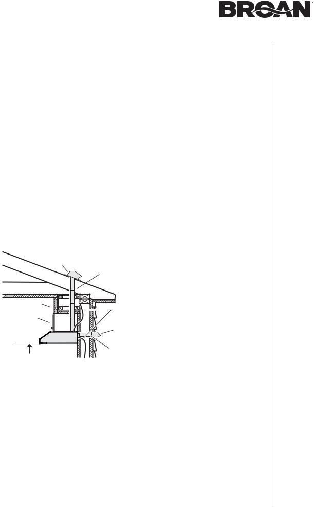
Install Ductwork (Ducted Installations Only)
|
ROOF CAP |
3¼" X 10" OR |
|
|
|
|
|
7" ROUND DUCT |
|
|
(FOR VERTICAL |
|
|
DISCHARGE) |
SOFFIT |
|
HOUSE WIRING |
|
|
|
CABINET |
|
(TOP OR BACK OF HOOD) |
|
|
WALL CAP |
|
HOOD |
|
|
3¼" X 10" DUCT |
18" MIN - 24" MAX |
(FOR HORIZONTAL DISCHARGE) |
ABOVE COOKING SURFACE
NOTE: Distances over 24” are at the installer and user discretion.
1 ] Determine whether hood will discharge vertically (3¼” x 10” or 7” round), or horizontally (3¼” x 10” only).
2 ] Decide where the ductwork will run between the hood and the outdoors.
3 ] Choose a straight, short duct run to allow the hood to perform most efficiently. Long duct runs, elbows and transitions will reduce the performance of the hood. Use as few of them as possible. When possible, use at least 2 foot straight runs before any turns. Larger ductwork may be required for best performance with longer duct runs.
4 ] Install wall cap or roof cap (sold separately). Connect metal ductwork to cap and work back towards the hood location. Use 2” metal foil duct tape to seal the joints between ductwork sections.
INSTALLATION |
MANUAL INSTALLATION |
7

INSTALLATION MANUAL |
INSTALLATION |
8
Contents
Before proceeding to the installation, check the contents of the box. If items are missing or damaged, contact the manufacturer.
Make sure that the following items are included:
* FIND INSIDE
OF HOOD
|
(2) GREASE FILTERS |
|
|
|
|
|
|
|
|
(1) 3¼” X 10” |
(1) 7” ROUND |
||||||||||||||||||||||||
|
|
|
|
|
|
|
|
DAMPER ASSEMBLY* |
DUCT CONNECTOR |
||||||||||||||||||||||||||
|
|
|
|
|
|
|
|
|
|
|
|
|
|
|
|
|
|
|
|
|
|
|
|
|
|
|
|
|
|||||||
|
|
|
|
|
|
|
|
|
|
|
|
|
|
|
|
|
|
|
|
|
|
|
|
|
|
|
|
|
|||||||
|
|
|
|
|
|
|
|
|
|
|
|
|
|
|
|
|
|
|
|
|
|
|
|
EZ1 COMPONENTS |
|
||||||||||
|
|
|
|
|
|
|
|
|
|
|
|
|
|
|
|
|
|
M |
|
|
|
|
|
|
|
|
|
|
|
|
|
|
|||
|
|
|
|
|
|
|
|
|
|
|
|
|
|
|
|
|
|
7” R D |
OR |
R D |
|
|
|
|
|
|
|||||||||
|
C |
|
|
|
|
|
|
|
|
|
|
|
|
|
|
|
M |
|
|
|
|
|
|
|
|
|
|
|
|
|
|
|
|
|
|
|
|
|
|
|
|
|
|
|
|
|
|
|
|
|
|
|
|
|
|
|
|
|
|
|
|
|
|
|
|
|
|
|
|
||
|
|
|
|
|
|
|
|
|
|
|
|
|
|
|
|
C |
7 |
OU |
|
C |
|
|
|
|
|
|
|||||||||
|
|
|
|
|
|
|
|
|
|
T |
|
S |
|
|
|
|
|
|
|
|
|
|
|
|
|||||||||||
|
|
|
|
|
8” |
|
|
|
|
|
|
|
|
|
|
|
(1) TEMPLATE FOR DUCTING |
||||||||||||||||||
|
|
|
|
|
|
|
|
|
|
|
|
C |
C |
O |
|
C |
|
|
|
|
|||||||||||||||
|
|
|
|
|
|
|
|
|
|
|
|
7 . |
|
|
|
|
|
|
|
|
|
|
|||||||||||||
|
|
|
|
|
|
|
|
|
|
|
|
L7½” |
|
|
|
|
|
|
|
|
|
|
|
|
|
|
|
|
|
|
|||||
|
|
VE |
|
|
|
|
|
|
|
|
|
|
|
HAUST |
|
|
|
|
(PRINTED BOTH SIDES) |
||||||||||||||||
|
|
RTICAL |
|
|
|
EX |
|
|
|
|
|||||||||||||||||||||||||
|
|
|
|
|
|
|
|
|
|
|
|
|
|
10½” |
|
|
|
|
|
|
4¼” |
|
|
|
|
|
|
|
|
|
|
|
|
||
|
|
|
|
|
|
|
|
|
|
|
|
|
|
|
|
|
|
|
|
|
|
|
|
|
|
|
|
|
|
|
|
||||
|
|
|
|
|
|
|
|
|
14½” |
|
|
|
|
|
|
|
|
|
|
|
|
|
|
|
A |
B |
|
|
|||||||
|
|
C |
|
|
|
|
|
|
|
|
|
|
|
|
|
|
|
|
C |
|
|
|
|
|
|
||||||||||
|
|
|
|
Place this edge against back wall Appuyer ce bord au mur arrière Apoyar este borde contra la pared de atrás |
|
|
|
|
(2) INSTALLATION BRACKETS** |
||||||||||||||||||||||||||
|
|
|
|
|
|
|
|
||||||||||||||||||||||||||||
|
|
|
|
|
|
|
|
||||||||||||||||||||||||||||
|
|
|
|
|
|
|
|
||||||||||||||||||||||||||||
|
|
|
|
|
|
|
|
|
|
|
|
|
|
|
|
|
|
|
|
|
|
|
|
|
|
|
|
|
|
|
|
|
|
||
|
|
|
|
|
|
|
|
|
|
|
|
|
|
|
|
|
|
|
|
|
|
|
|
|
|
|
|
|
|
|
|
|
|
||
|
|
|
|
|
|
|
|
|
|
|
|
|
|
|
|
|
|
|
|
|
|
|
|
|
|
|
|
|
|
|
|
|
|
FOR FRAMED CABINET |
|
|
|
|
|
|
|
|
|
|
|
|
|
|
|
|
|
|
|
|
|
|
|
|
|
|
|
|
|
|
|
|
|
|
|
(2) INSTALLATION BRACKETS** |
|
|
|
|
|
|
|
|
|
|
|
|
|
|
|
|
|
|
|
|
|
|
|
|
|
|
|
|
|
|
|
|
|
|
|
||
|
|
|
|
|
|
|
|
|
|
|
|
|
|
|
|
|
|
|
|
|
|
|
|
|
|
|
|
|
|
|
|
|
|
FOR FRAMELESS CABINET |
|
|
|
|
|
|
|
|
|
|
|
|
|
|
|
|
|
|
|
|
|
|
|
|
|
|
|
|
|
|
|
|
|
|
|
** FIND EZ1 BRACKET |
|
|
|
|
|
|
|
|
|
|
|
|
|
|
|
|
|
|
|
|
|
|
|
|
|
|
|
|
|
|
|
|
|
|
|
ATTACHED INSIDE OF HOOD |
|
|
|
|
|
|
|
|
|
|
|
|
|
|
|
|
|
|
|
|
|
|
|
|
|
|
|
|
|
|
|
|
|
||||
|
|
|
|
|
|
|
|
|
|
|
|
|
|
|
|
(1) PARTS BAG*** CONTAINING: |
|||||||||||||||||||
|
|
|
|
|
|
|
|
|
|
|
|
|
|
|
|
|
|
|
|
|
|
|
|
|
|
|
|
|
|
|
|
|
(4) NO. 8-18 X 1/2” |
||
|
|
|
|
|
|
|
|
|
|
|
|
|
|
|
|
|
|
|
|
|
|
|
|
|
|
|
|
|
|
|
|
|
|||
|
|
|
|
|
|
|
|
|
|
|
|
|
|
|
|
|
|
|
|
|
|
|
|
|
|
|
|
|
|
|
|
|
|||
|
|
|
|
|
|
|
|
|
|
|
|
|
|
|
|
|
|
|
|
|
|
|
|
|
|
|
|
|
|
|
|
|
METAL SCREWS |
||
|
|
|
|
|
|
|
|
|
|
|
|
|
|
(6) NO. 8 X 5/8” |
|
(6) NO. 8 X 1/2” |
|||||||||||||||||||
|
|
|
|
|
|
|
|
|
|
|
|
|
|
|
|
RD. HD. |
|
|
|
|
|
||||||||||||||
|
|
|
|
|
|
|
|
|
|
|
|
|
|
|
|
|
|
|
|
|
COUNTERSUNK |
||||||||||||||
|
|
|
|
|
|
|
|
|
|
|
|
|
|
WOOD SCREWS |
|
||||||||||||||||||||
|
|
|
|
|
|
|
|
|
|
|
|
|
|
|
WOOD SCREWS |
||||||||||||||||||||
|
|
|
|
|
|
|
|
|
|
|
|
|
|
|
|
|
|
|
|
|
|
|
|
|
|
|
|
|
|
|
|
|
|
|
|
|
|
|
|
|
|
|
|
|
|
|
|
|
|
|
|
(1) BULB SUCTION |
*** FIND PARTS BAG BEHIND |
||||||||||||||||||
|
|
|
|
|
|
|
|
|
|
|
|
|
|
|
|
THE DAMPER ASSEMBLY |
|||||||||||||||||||
|
|
|
|
|
|
|
|
|
|
|
|
|
|
|
|
|
CUP TOOL |
||||||||||||||||||
|
|
|
|
|
|
|
|
|
|
|
|
|
|
|
|
|
|
INSIDE OF HOOD |
|||||||||||||||||
 Loading...