


BP007-1HZC-FRS
Bosch BP007-1HZC-FRS, CP030-1VTN-FRT, BP007-1HZN-FRS, BP007-1HZC-FLS, BP007-1HZN-FLS Installation And Maintenance Manual
...
Installation and Maintenance Manual
CP/BP Series
6 720 220 045
Revised 05-12

©Copyright 2012 Bosch, Inc All rights reserved
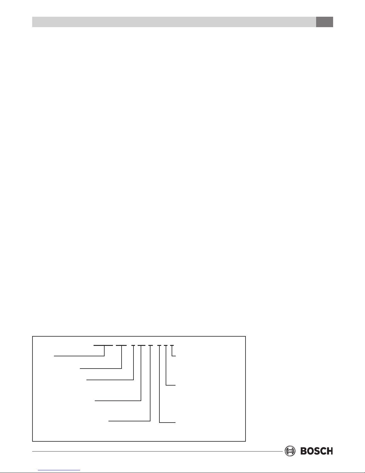
Table of Contents
TABLE OF CONTENTS
CP/BP Series
3
Model Nomenclature ............................................. 3
Initial Inspection ................................................... 4
General Description .............................................. 4
Moving and Storage .............................................. 4
Safety Considerations ........................................... 4
Location ................................................................ 4
Installation ............................................................ 5
Mounting Vertical Units ......................................... 5
Mounting Horizontal Units .................................... 5
Condensate Drain ................................................. 6
Duct System .......................................................... 6
Electrical ............................................................... 7
Thermostat Connections ...................................... 8
Safety Devices and the UPM Controller ................. 8
Sequence Of Operation ...................................... 10
Unit Options........................................................ 10
Fluid Differential Pressure Switch ....................... 13
Earth Coupled Systems ....................................... 15
Unit Start-up ....................................................... 15
Heat Recovery Package ....................................... 15
Water Tank Preparation ....................................... 16
HR Water Piping ................................................. 16
Typical Connection Piping ................................... 16
Water Tank Rell ................................................. 17
Initial Start up ..................................................... 17
Maintenance ....................................................... 17
In-warranty Material Return ................................ 18
Unit Specications .............................................. 18
Physical Data ................................................ 18
Dimensions ................................................... 19
Fluid Pressure Drops ..................................... 20
Air Temperature Rise/Fall .............................. 21
Refrigerant Pressure Ranges ......................... 22
Blower Performance ..................................... 23
Water Piping ....................................................... 13
Well Water Systems ............................................. 13
Fresh Water Systems ........................................... 14
MODEL NOMENCLATURE
CP/BP 048 - 1 VT C - F L T
SERIES:
CP/BP
NOMINAL CAPACITY:
MBTUH
VOLTAGE DESIGNATION:
1- 208-230/1/60
CABINET CONFIGURATION:
VT - VERTICAL
HZ - HORIZONTAL
WATER TO REFRIGERANT HEAT EX:
C - COPPER
N - CUPRO-NICKEL
Typical Wiring Diagrams ...................................... 24
Unit Check-out Sheet .......................................... 28
Troubleshooting .................................................. 29
SUPPLY AIR LOCATION:
T - TOP (VT ONLY)
S - STRAIGHT THRU (HZ ONLY)
E - END BLOW (HZ ONLY)
RETURN AIR LOCATION:
L - LEFT
R - RIGHT
WATER CONNECTION LOCATION
F - FRONT
Revised 05-12 Subject to change without prior notice
6 720 220 045
Initial Inspection
4
CP/BP Series
INITIAL INSPECTION
Be certain to inspect all cartons or crates on each
unit as received at the job site before signing the
freight bill. Verify that all items have been received
and that there are no visible damages; note any
shortages or damages on all copies of the freight
bill. In the event of damage or shortage, remember
that the purchaser is responsible for ling the
necessary claims with the carrier. Concealed
damages not discovered until after removing the
units from the packaging must be reported to the
carrier within 24 hours of receipt.
GENERAL DESCRIPTION
These Packaged System Heat Pumps provide the
best combination of performance and ef ciency
available. Safety devices are built into each unit to
provide the maximum system protection possible
when properly installed and maintained.
The CP/BP Water-to-Air Heat Pumps are
Underwriters Laboratories (UL) and (cUL) listed for
safety. The water-to-Air Heat Pumps are designed to
operate with entering uid temperature between
25°F to 80°F in the heating mode and between 50°F
to 110°F in the cooling mode. Ef ciencies and
capacities will vary as entering uid and return air
temperatures vary.
50°F Min. EWT for well water applications
suffi cient water fl ow to prevent freezing.
Antifreeze solution is required for all closed loop
applications where the fl uid temperature may drop
below 50°F. Cooling Tower/Boiler and Earth
Coupled (Geo Thermal) applications should have
suffi cient antifreeze solution to protect against
extreme conditions and equipment failure. Frozen
water coils are not covered under warranty.
This product should not be used for temporarily
heating/cooling during construction. Doing so
may affect the unit’s warranty.
MOVING AND STORAGE
If the equipment is not needed for immediate
installation upon its arrival at the job site, it should
be left in its shipping carton and stored in a clean,
dry area. Units must only be stored or moved in the
normal upright position as indicated by the “UP”
arrows on each carton at all times. If unit stacking is
required, stack units as follows: Vertical units less
than 6 tons, no more than two high; horizontal units
less than 6 tons, no more than three high. Do not
stack units larger than 6 tons.
SAFETY CONSIDERATIONS
Installation and servicing of this equipment can be
hazardous due to system pressure and electrical
components. Only trained and quali ed personnel
should install, repair, or service the equipment. Untrained
personnel can perform basic functions of maintenance
such as cleaning coils and replacing lters.
Before performing service or maintenance
operations on the system, turn off main power to
the unit. Electrical shock could cause personal
injury or death.
When working on equipment, always observe
precautions described in the literature, tags, and
labels attached to the unit. Follow all safety codes.
Wear safety glasses and work gloves. Use a
quenching cloth for brazing, and place a re
extinguisher close to the work area.
The blower motor should only be operated when a
duct is installed and secured to heat pump duct
collar in order to avoid possible injury.
LOCATION
Locate the unit in an indoor area that allows easy
removal of the lter and access panels, and has
enough room for service personnel to perform
maintenance or repair. Provide suf cient room to
make uid, electrical, and duct connection(s). If the
unit is located in a con ned space such as a closet,
provisions must be made for return air to freely
enter the space. On horizontal units, allow
adequate room below the unit for a condensate
drain trap and do not locate the unit above supply
piping. These units are not approved for outdoor
installation; therefore, they must be installed inside
the structure being conditioned.
Do not locate units in areas that are subject to
freezing.
6 720 220 045
Subject to change without prior notice Revised 05-12

VIBRATION
PAD
FULL SIZE
Installation
CP/BP Series
5
INSTALLATION
Remove shipping block under blower housing.
Loosen compressor mounting bolts.
The installer should comply with all local codes
and regulations which govern the installation of
this type of equipment. Local codes and
regulations take precedent over any
recommendations contained in these instructions.
In lieu of local codes, the equipment should be
installed in accordance with the recommendations
made by the National electric code, and in
accordance with the recommendations made by
the National Board of Fire Underwriters. All local
seismic codes for seismic restraint of equipment,
piping, and duct work shall be strictly adhered to.
MOUNTING VERTICAL UNITS
Vertical units up to six tons are available in left or
right air return con gurations. Vertical units should
be mounted level on a vibration absorbing pad
slightly larger than the base to minimize vibration
transmission to the building structure. It is not
necessary to anchor the unit to the oor. (See
Figure #1).
MOUNTING HORIZONTAL UNITS
While horizontal units may be installed on any
level surface strong enough to hold their weight,
they are typically suspended above a ceiling by
threaded rods. The rods are usually attached to
the unit corners by hanger bracket kits (P/N
930-008). (See Figure #2). The rods must be
securely anchored to the ceiling. Refer to the
hanging bracket assembly and installation
instructions for details. Horizontal units installed
above the ceiling must conform to all local codes.
An auxiliary drain pan if required by code should
be at least four inches larger than the bottom of
the heat pump. Plumbing connected to the heat
pump must not come in direct contact with joists,
trusses, walls, etc.
If the unit is located in a con ned space such as a
closet, provisions must be made for return air to
freely enter the space.
VIBRATION
PAD
FULL SIZE
Figure #1 – Vertical unit on vibration pad
Figure #2 – Typical horizontal unit hanging bracket
Some applications require an attic oor installa-
tion of the horizontal unit. In this case the unit
should be set in a full size secondary drain pan on
top of a vibration absorbing mesh. The secondary
drain pan prevents possible condensate over ow
or water leakage damage to the ceiling. The
secondary drain pan is usually placed on a plywood base isolated from the ceiling joists by
additional layers of vibration absorbing mesh. In
both cases, a 3/4” drain connected to this secondary pan should be run to an eave and able to drain
to a location that will be noticeable. If the unit is
located in a crawl space, the bottom of the unit
must be at least 4” above grade to prevent ood-
ing of the electrical parts due to heavy rains.
Locate the heat pump unit in an area that provides
suf cient room to make water and electrical
connections, allowing easy removal of the access
Revised 05-12 Subject to change without prior notice
6 720 220 045
6
Condensate Drain
CP/BP Series
panels, and replacement of air lters for routine
maintenance. This will ensure proper work space for
service personnel to perform maintenance or repair.
See Unit Specications for replacement lter sizes
in the back of this manual to ensure proper
clearances are provided during installation. Allow
adequate room below the unit for a condensate
drain trap on horizontal units.
Water freezes at 32°F. Frozen water coils are not
covered under the limited product warranty. It is
the installer’s responsibility to insure that the heat
pump unit is installed in a location or have taken
the proper precautions in order to prevent
rupturing the water coil due to freezing conditions.
The heat pump unit is designed for conditioned
space installation only. If the source water is
subjected to conditions where ambient
temperatures can fall below freezing, some form of
freeze protection should be employed. In an open
loop system this may entail running the water pump
continuously to prevent freezing. An antifreeze
solution wherever possible should be used if water
will be subject to freezing. Consult the factory in
these instances for guidance.
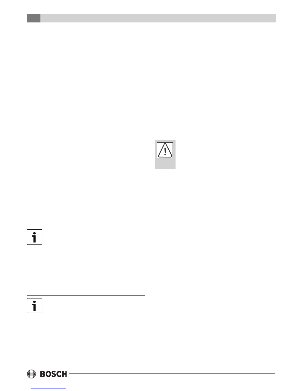
CONDENSATE DRAIN
A drain line must be connected to the heat pump
and pitched away from the unit a minimum of 1/8”
per foot to allow the condensate to ow away from
the unit.
Figure #3 – Heat Pump Condensate Trapping
(Heat Pumps are not internally trapped). A vertical
air vent is sometimes required to avoid air pockets
(See Figure #3). The length of the trap depends on
the amount of positive or negative pressure on the
drain pan. A second trap must not be included.
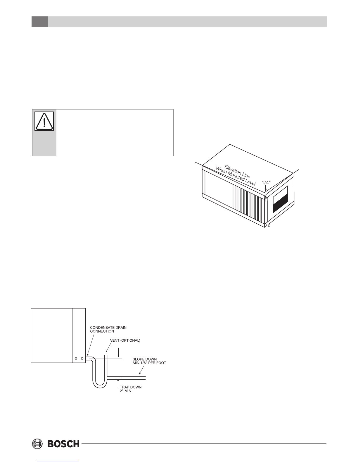
The horizontal unit should be pitched
approximately 1/4” towards the drain in both
directions, to facilitate condensate removal. See
Figure 4 below.
Figure #4 – Sloped horizontal unit installation
DUCT SYSTEM
A supply air outlet collar and return air duct ange
are provided on all units to facilitate duct
connections. See Unit Specications for duct collar
connection sizes in the back of this manual.
A exible connector is recommended for supply
and return air duct connections on metal duct
systems. All metal ducting should be insulated with
a minimum of one inch duct insulation to avoid heat
loss or gain and prevent condensate forming during
the cooling operation. Application of the unit to
uninsulated duct work is not recommended as the
unit’s performance will be adversely affected. Do
not connect ducts directly to the blower outlet;
factory supplied duct collars should be used for
connection. The factory provided air lter must be
removed when using a lter back return air grill. The
factory lter should be left in place on a free return
system.
This connection must be in conformance with local
plumbing codes. A trap must be installed in the
condensate line to insure free condensate ow.
6 720 220 045
If the unit will be installed in a new installation
which includes new duct work, the installation
should be designed using current ASHRAE
procedures for duct sizing. If the unit is to be
connected to existing ductwork, a check should be
made to assure that the duct system has the
Subject to change without prior notice Revised 05-12

Electrical
CP/BP Series
7
capacity to handle the air required for the unit
application. If the duct system is too small, larger
ductwork should be installed. Check for existing
leaks and repair as necessary to ensure a tight air
seal within duct. The duct system and all diffusers
should be sized to handle the designed air ow
quietly. To maximize sound attenuation of the unit
blower, the supply and return air plenums should
be insulated. There should be no direct straight air
path thru the return air grille into the heat pump.
The return air inlet to the heat pump must have at
least one 90 degree turn away from the space
return air grille. If air noise or excessive air ow are
a problem, the blower speed can be changed to a
lower speed to reduce air ow. (Refer to ECM
motor speeds and settings in Table #1)
Always disconnect power to the unit before
changing motor speed to prevent damage to
the motor, injury or death due to electrical
shock.
ELECTRICAL
Always disconnect power to the unit before
servicing to prevent injury or death due to
electrical shock or contact with moving parts.
All eld wiring must comply with local and national
re, safety and electrical codes. Power to the unit
must be within the operating voltage range
indicated on the unit’s nameplate. On three phase
units, phases must be balanced within 2%.
Operating the unit with improper line voltage
or with excessive phase imbalance is
hazardous to the unit and constitutes abuse
and is not covered under warranty.
Properly sized fuses or HACR circuit breakers must
be installed for branch circuit protection. See
equipment rating plates for proper size.
The heat pump units are provided with a concentric
knock-out in the front right corner post for
attaching common trade sizes of conduit. Route
power supply wiring through this opening. Flexible
wiring and conduit should be used to isolate
vibration and noise from the building structure. Be
certain to connect the ground lead to the ground
lug in the control box. Connect the power leads as
indicated on the unit wiring diagrams.
Table 1: CP/BP Motor CFM Selection (ECM Motor)otor Only)
Units
CP/BP015 450-153 1/3 LOW MED HIGH - -
CP/BP018 450-153 1/3 - LOW - MED HIGH
CP/BP024 450-157 1/3 LOW MED HIGH - -
CP/BP030 450-154 1/3 LOW MED HIGH - -
CP/BP036 450-158 3/4 LOW MED HIGH - -
CP/BP042 450-155 3/4 LOW MED HIGH - -
CP/BP048 450-155 3/4 - LOW MED HIGH -
CP/BP060 450-156 1 LOW MED HIGH - -
CP/BP070 450-156 1 LOW - - MED HIGH
Revised 05-12 Subject to change without prior notice
Motor Part
Number
Motor HP Tap1 Tap2 Tap3 Tap4 Tap5
6 720 220 045

8
Thermostat Connections
CP/BP Series
THERMOSTAT CONNECTIONS
Thermostat wiring is connected to a 7 position low
voltage terminal block in the electrical box. The
thermostat connections and their functions are as
follows:
Y Compressor Operation
G Fan
O Reversing Valve (energized in cooling)
C Transformer 24 VAC Common – 3 Connections
R Transformer 24 VAC Hot
If the unit is being connected to a thermostat with a
malfunction light, this connection is made at the
unit alarm output.
If the thermostat is provided with a malfunction
light powered off of the common (C) side of the
transformer, a jumper between “R” and “COM”
terminal of “ALR” contacts must be made.
below or remains at freeze limit trip for 30
seconds, the controller will shut down the
compressor and enter into a soft lockout
condition. The default freeze limit trip is 30°F,
however this can be changed to 15°F by cutting
the R42 resistor located on top of DIP switch SW1.
• The optional condensate over ow protection
sensor (standard on horizontal units) is located in
the drain pan of the unit and connected to the
‘COND’ terminal on the UPM board.
If the thermostat is provided with a malfunction
light powered off of the hot (R) side of the
transformer, then the thermostat malfunction light
connection should be connected directly to the
(ALR) contact on the unit’s UPM board.
SAFETY DEVICES AND THE
UPM CONTROLLER
Each unit is factory provided with a Unit Protection
Module (UPM) that controls the compressor operation and monitors the safety controls that protect
the unit.
Safety controls include the following:
• High pressure switch located in the refrigerant
discharge line and wired across the HPC
terminals on the UPM
• Low pressure switch located in the unit
refrigerant suction line and wired across
terminals LPC1 and LPC2 on the UPM.
Freeze
Protection
Sensor
• Optional freeze protection sensor, mounted close
to condensing water coil, monitors refrigerant
temperature between condensing water coil and
thermal expansion valve. If temperature drops
6 720 220 045
If freeze protection sensor is not installed, a
jumper between freeze contacts must be installed
on the UPM board otherwise unit will not start.
Subject to change without prior notice Revised 05-12
Safety Devices and the UPM Controller
CP/BP Series
9
The UPM includes the following features:
• ANTI-SHORT CYCLE TIME—5 minute delay on
break timer to prevent compressor short cycling.
• RANDOM START—Each controller has a unique
random start delay ranging from 270 to 300 seconds to
reduce the chances of multiple units simultaneously
starting after initial power up or after a power
interruption, creating a large electrical spike.
• LOW PRESSURE BYPASS TIMER—If the compressor is
running and the low pressure switch opens, then the
control will keep the compressor on for 120 seconds.
After 2 minutes if the low pressure switch remains
open, the control will shut down the compressor and
enter a soft lockout. The compressor will not be
energized until the low pressure switch closes and the
anti-short cycle time delay expires. If the low pressure
switch opens 2–4 times in 1 hour, the unit will enter a
hard lock out and need to be reset.
• BROWNOUT/SURGE/POWER INTERRUPTION
PROTECTION—The brownout protection in the UPM
board will shut down the compressor if the
incoming power falls below 18 VAC. The compressor
will remain off till the voltage goes above 18 VAC and
the anti short cycle timer (300 seconds) times out.
The unit will not go into a hard lockout.
• MALFUNCTION OUTPUT—Alarm output is Normally
Open (NO) dry contact. If 24 VAC output is needed
R must be wired to the ALR-COM terminal; 24VAC
will be available on the ALR-OUT terminal when the
unit is in alarm condition. If pulse is selected the
alarm output will be pulsed. The fault output will
depend on the dip switch setting for “ALARM”. If it
set to “CONST’, a constant signal will be produced
to indicate a fault has occurred and the unit
requires inspection to determine the type of fault. If
it is set to “PULSE”, a pulse signal is produced and a
fault code is detected by a remote device indicating
the fault. See L.E.D. Fault Indication below for blink
code explanations. The remote device must have a
malfunction detection capability when the UPM
board is set to “PULSE”.
• TEST DIP SWITCH—A test dip switch is provided
to reduce all time delay settings to 10 seconds
during troubleshooting or veri cation of unit
operation. Note that operation of the unit while in
test mode can lead to accelerated wear and
premature failure of the unit. The “TEST” switch
must be set back to “NO” for normal operation.
• FREEZE SENSOR—The freeze sensor input is
active all the time, if a freeze option is not selected
the freeze terminals will need a jumper. There are
2 con gurable freeze points, 30°F & 15°F. The unit
will enter a soft lock out until the temperature
climbs above the set point and the anti-short cycle
time delay has expired. The freeze sensor will shut
the compressor output down after 90 seconds of
water ow loss and report a freeze condition. It is
recommended to have a ow switch to prevent the
unit from running if water ow is lost.
If unit is employing a fresh water system (no
anti-freeze protection), it is extremely important to
have the “Freeze” jumper R42 resistor set to 30°F
in order to shut down the unit at the appropriate
leaving water temperature and protect your heat
pump from freezing if a freeze sensor is included.
• L.E.D. FAULT INDICATION—Two L.E.D. indicators
are provided:
• Green: Power L.E.D. indicates 18—30 VAC
present at the board.
• Red: Fault indicator with blink codes as follows:
- One blink—High pressure lockout
- Two blinks—Low pressure lockout
- Three blinks—Freeze sensor lockout
- Four blinks—Condensate over ow
- Five blinks—Brownout
• INTELLIGENT RESET—If a fault condition is initiated,
the 5 minute delay on break time period is initiated
and the unit will restart after these delays expire.
During this period the fault LED will indicate the
cause of the fault. If the fault condition still exists or
occurs 2 or 4 times (depending on 2 or 4 setting for
Lockout dip switch) before 60 minutes, the unit will
go into a hard lockout and requires a manual lockout
reset. A single condensate over ow fault will cause
the unit to go into a hard lockout immediately, and
will require a manual lockout reset.
Revised 05-12 Subject to change without prior notice
6 720 220 045

10
CP/BP Series
Sequence of Operation
• LOCKOUT RESET—A hard lockout can be reset by
turning the unit thermostat off and then back on
when the “RESET” dip switch is set to “Y” or by
shutting off unit power at the circuit breaker
when the “RESET” dip switch is set to “R”.
The blower motor will remain active during a
lockout condition.
• UPM BOARD DEFAULT SETTINGS—Your UPM
board will come from the factory with the
following default settings:
• Freeze—“Terminals not jumped” on all the time
• Temp—30°F
• Lockout—2
• Reset—“Y”
• Alarm—“PULSE”
• Test—“NO”
• Dry Contact—“Normally Open (NO)”
Considerations
1. Always check incoming line voltage power
supply and secondary control voltage for
adequacy. Transformer primaries are dual
tapped for 208 and 230 volts. Connect the
appropriate tap to ensure a minimum of 18 volts
secondary control voltage. 24 volts is ideal for
best operation.
SEQUENCE OF OPERATION
Cooling Mode
See Typical Wiring Diagrams at the end of the
document. Energizing the “O” terminal energizes
the unit reversing valve in the cooling mode. The fan
motor starts when the “G” terminal is energized.
When the thermostat calls for cooling (Y), the loop
pump or solenoid valve if present is energized and
compressor will start.
Once the thermostat is satis ed, the compressor
shuts down accordingly and the fan ramps down to
either fan only mode or off over a span of 30 seconds
(ECM Motors).
Note that a fault condition initiating a lockout will
de-energize the compressor.
Heating Mode
Heating operates in the same manner as cooling,
but with the reversing valve de-energized. The
compressor will run until the desired setpoint
temperature on the thermostat is achieved.
Once the thermostat is satis ed, the compressor
shuts down and the fan ramps down in either fan
only mode or turns off over a span of 30 seconds.
Auxiliary electric heating coils are not available on
the BP/CP product line.
UNIT OPTIONS
HOT GAS REHEAT (HGR)
2. Long length thermostat and control wiring
leads may create voltage drop. Increase wire
gauge or up-size transformers may be required
to insure minimum secondary voltage supply.
3. FHP recommends the following guidelines for
wiring between a thermostat and the unit: 18
GA up to 60 foot, 16 GA up to 100 ft and 14 GA
up to 140 ft.
4. Do not apply additional controlled devices to
the control circuit power supply without
consulting the factory. Doing so may void
equipment warranties.
5. Check with all code authorities on requirements
involving condensate disposal/over ow
protection criteria.
6 720 220 045
Hot gas reheat allows the user to not only control
space temperature, but also humidity levels within
the conditioned space. An excess of moisture in the
space can allow mold growth leading to damage in
the structure or interior surfaces as well as
reducing the air quality and creating an unhealthy
environment.
The typical control of a unit is by a thermostat that
senses the temperature in the space. By utilizing a
humidistat in addition to the thermostat we are
able to monitor the humidity levels in the space as
well. The HGR option allows cooling and
dehumidi cation to satisfy both the thermostat and
humidistat.
Subject to change without prior notice Revised 05-12
 Loading...