


BNO055
Data sheet
BNO055
Intelligent 9-axis absolute orientation sensor
BNO055: data sheet
Document revision
1.4
Document release date
June 2016
Document number
BST-BNO055-DS000-14
Technical reference code(s)
0 273 141 209
Notes
Data in this document are subject to change without notice. Product
photos and pictures are for illustration purposes only and may differ from
the real product’s appearance.
User Motion
• Quaternion
• Linear Acceleration
• Rotation
• Gravity
• Robust Heading
Bosch Sensortec

BNO055
Data sheet
Page 2
BNO055
INTELLIGENT ABSOLUTE ORIENTATION SENSOR, 9-AXIS SENSOR FUSION
ALL-IN-ONE WINDOWS 8.x COMPLIANT SENSOR HUB
Basic Description
Key features:
Outputs fused sensor data Quaternion, Euler angles, Rotation vector,
Linear acceleration, Gravity, Heading
3 sensors in one device an advanced triaxial 16bit gyroscope, a versatile,
leading edge triaxial 14bit accelerometer and a
full performance geomagnetic sensor
Small package LGA package 28 pins
Footprint 3.8 x 5.2 mm², height 1.13 mm²
Power Management Intelligent Power Management: normal,
low power and suspend mode available
Common voltage supplies V
Digital interface HID-I2C (Windows 8 compatible), I²C, UART
V
Consumer electronics suite MSL1, RoHS compliant, halogen-free
Key features of integrated sensors:
voltage range: 2.4V to 3.6V
DD
voltage range: 1.7V to 3.6V
DDIO
Operating temperature: -40°C ... +85°C
Accelerometer features
Programmable functionality Acceleration ranges ±2g/±4g/±8g/±16g
Low-pass filter bandwidths 1kHz - <8Hz
Operation modes:
- Normal
- Suspend
- Low power
- Standby
- Deep suspend
On-chip interrupt controller Motion-triggered interrupt-signal generation for
- any-motion (slope) detection
- slow or no motion recognition
- high-g detection
BST-BNO055-DS000-14 | Revision 1.4 | June 2016 Bosch Sensortec
© Bosch Sensortec GmbH reserves all rights even in the event of industrial property rights. We reserve all rights of disposal su ch as copying and passing on
to third parties. BOSCH and the symbol are registered trademarks of Robert Bosch GmbH, Germany.
Note: Specifications within this document are subject to change without notice.

BNO055
Data sheet
Page 3
Gyroscope features
Programmable functionality Ranges switchable from ±125°/s to ±2000°/s
Low-pass filter bandwidths 523Hz - 12Hz
Operation modes:
- Normal
- Fast power up
- Deep suspend
- Suspend
- Advanced power save
On-chip interrupt controller Motion-triggered interrupt-signal generation for
- any-motion (slope) detection
- high rate
Magnetometer features
Flexible functionality Magnetic field range typical ±1300µT (x-, y-axis);
±2500µT (z-axis)
Magnetic field resolution of ~0.3µT
Operating modes:
- Low power
- Regular
- Enhanced regular
- High Accuracy
Power modes:
- Normal
- Sleep
- Suspend
- Force
Typical applications
Navigation
Robotics
Fitness and well-being
Augmented reality
Context awareness
Tablets and ultra-books
BST-BNO055-DS000-14 | Revision 1.4 | June 2016 Bosch Sensortec
© Bosch Sensortec GmbH reserves all rights even in the event of industrial property rights. We reserve all rights of disposal su ch as copying and passing on
to third parties. BOSCH and the symbol are registered trademarks of Robert Bosch GmbH, Germany.
Note: Specifications within this document are subject to change without notice.

BNO055
Data sheet
Page 4
General description
The BNO055 is a System in Package (SiP), integrating a triaxial 14-bit accelerometer, a
triaxial 16-bit gyroscope with a range of ±2000 degrees per second, a triaxial geomagnetic
sensor and a 32-bit cortex M0+ microcontroller running Bosch Sensortec sensor fusion
software, in a single package.
The corresponding chip-sets are integrated into one single 28-pin LGA 3.8mm x 5.2mm x
1.1 mm housing. For optimum system integration the BNO055 is equipped with digital bidirectional I2C and UART interfaces. The I2C interface can be programmed to run with the
HID-I2C protocol turning the BNO055 into a plug-and-play sensor hub solution for devices
running the Windows 8.0 or 8.1 operating system.
BST-BNO055-DS000-14 | Revision 1.4 | June 2016 Bosch Sensortec
© Bosch Sensortec GmbH reserves all rights even in the event of industrial property rights. We reserve all rights of disposal su ch as copying and passing on
to third parties. BOSCH and the symbol are registered trademarks of Robert Bosch GmbH, Germany.
Note: Specifications within this document are subject to change without notice.

BNO055
Data sheet
Page 5
Contents
BASIC DESCRIPTION ........................................................................................................... 2
SPECIFICATION .................................................................................................................. 12
1.1 ELECTRICAL SPECIFICATION .......................................................................................... 12
1.2 ELECTRICAL AND PHYSICAL CHARACTERISTICS, MEASUREMENT PERFORMANCE ................ 13
2. ABSOLUTE MAXIMUM RATINGS .................................................................................. 17
3. FUNCTIONAL DESCRIPTION ......................................................................................... 18
3.1 ARCHITECTURE ............................................................................................................. 18
3.2 POWER MANAGEMENT ................................................................................................... 18
3.2.1 NORMAL MODE ....................................................................................................................... 19
3.2.2 LOW POWER MODE ................................................................................................................. 19
3.2.3 SUSPEND MODE ..................................................................................................................... 20
3.3 OPERATION MODES ...................................................................................................... 20
3.3.1 CONFIG MODE ........................................................................................................................ 22
3.3.2 NON-FUSION MODES .............................................................................................................. 22
3.3.3 FUSION MODES ....................................................................................................................... 22
3.4 AXIS REMAP.................................................................................................................. 24
3.5 SENSOR CONFIGURATION.............................................................................................. 26
3.5.1 DEFAULT SENSOR CONFIGURATION .......................................................................................... 26
3.5.2 ACCELEROMETER CONFIGURATION .......................................................................................... 27
3.5.3 GYROSCOPE CONFIGURATION .................................................................................................. 28
3.5.4 MAGNETOMETER CONFIGURATION............................................................................................ 29
3.6 OUTPUT DATA ............................................................................................................... 30
3.6.1 UNIT SELECTION...................................................................................................................... 30
3.6.2 DATA OUTPUT FORMAT ............................................................................................................ 30
3.6.3 FUSION OUTPUT DATA RATES .................................................................................................. 31
3.6.4 SENSOR CALIBRATION DATA ..................................................................................................... 31
3.6.5 OUTPUT DATA REGISTERS ....................................................................................................... 33
3.7 DATA REGISTER SHADOWING ......................................................................................... 37
3.8 INTERRUPTS ................................................................................................................. 38
3.8.1 INTERRUPT PIN ....................................................................................................................... 38
3.8.2 INTERRUPT SETTINGS ............................................................................................................. 38
3.9 SELF-TEST ................................................................................................................... 46
3.9.1 POWER ON SELF TEST (POST) ............................................................................................... 46
3.9.2 BUILD IN SELF TEST (BIST) ..................................................................................................... 46
3.10 BOOT LOADER ............................................................................................................ 46
3.11 CALIBRATION .............................................................................................................. 47
3.11.1 ACCELEROMETER CALIBRATION ............................................................................................. 47
3.11.2 GYROSCOPE CALIBRATION .................................................................................................... 47
3.11.3 MAGNETOMETER CALIBRATION .............................................................................................. 47
3.11.4 REUSE OF CALIBRATION PROFILE .......................................................................................... 48
BST-BNO055-DS000-14 | Revision 1.4 | June 2016 Bosch Sensortec
© Bosch Sensortec GmbH reserves all rights even in the event of industrial property rights. We reserve all rights of disposal su ch as copying and passing on
to third parties. BOSCH and the symbol are registered trademarks of Robert Bosch GmbH, Germany.
Note: Specifications within this document are subject to change without notice.

BNO055
Data sheet
Page 6
4. REGISTER DESCRIPTION .............................................................................................. 49
4.1 GENERAL REMARKS ...................................................................................................... 49
4.2 REGISTER MAP ............................................................................................................. 50
4.2.1 REGISTER MAP PAGE 0 ........................................................................................................... 50
4.2.2 REGISTER MAP PAGE 1 ........................................................................................................... 53
4.3 REGISTER DESCRIPTION (PAGE 0).................................................................................. 54
4.3.1 CHIP_ID 0X00 ....................................................................................................................... 54
4.3.2 ACC_ID 0X01 ........................................................................................................................ 54
4.3.3 MAG_ID 0X02 ....................................................................................................................... 54
4.3.4 GYR_ID 0X03 ........................................................................................................................ 54
4.3.5 SW_REV_ID_LSB 0X04 ....................................................................................................... 55
4.3.6 SW_REV_ID_MSB 0X05 ...................................................................................................... 55
4.3.7 BL_REV_ID 0X06 .................................................................................................................. 55
4.3.8 PAGE ID 0X07 ....................................................................................................................... 55
4.3.9 ACC_DATA_X_LSB 0X08 ..................................................................................................... 56
4.3.10 ACC_DATA_X_MSB 0X09 .................................................................................................. 56
4.3.11 ACC_DATA_Y_LSB 0X0A .................................................................................................. 56
4.3.12 ACC_DATA_Y_MSB 0X0B ................................................................................................. 56
4.3.13 ACC_DATA_Z_LSB 0X0C .................................................................................................. 57
4.3.14 ACC_DATA_Z_MSB 0X0D ................................................................................................. 57
4.3.15 MAG_DATA_X_LSB 0X0E .................................................................................................. 57
4.3.16 MAG_DATA_X_MSB 0X0F ................................................................................................. 57
4.3.17 MAG_DATA_Y_LSB 0X10 .................................................................................................. 58
4.3.18 MAG_DATA_Y_MSB 0X11 ................................................................................................. 58
4.3.19 MAG_DATA_Z_LSB 0X12 .................................................................................................. 58
4.3.20 MAG_DATA_Z_MSB 0X13 ................................................................................................. 58
4.3.21 GYR_DATA_X_LSB 0X14 .................................................................................................. 59
4.3.22 GYR_DATA_X_MSB 0X15 ................................................................................................. 59
4.3.23 GYR_DATA_Y_LSB 0X16 .................................................................................................. 59
4.3.24 GYR_DATA_Y_MSB 0X17 ................................................................................................. 59
4.3.25 GYR_DATA_Z_LSB 0X18 ................................................................................................... 60
4.3.26 GYR_DATA_Z_MSB 0X19 .................................................................................................. 60
4.3.27 EUL_DATA_X_LSB 0X1A ................................................................................................... 60
4.3.28 EUL_DATA_X_MSB 0X1B .................................................................................................. 60
4.3.29 EUL_DATA_Y_LSB 0X1C ................................................................................................... 61
4.3.30 EUL_DATA_Y_MSB 0X1D .................................................................................................. 61
4.3.31 EUL_DATA_Z_LSB 0X1E ................................................................................................... 61
4.3.32 EUL_DATA_Z_MSB 0X1F .................................................................................................. 61
4.3.33 QUA_DATA_W_LSB 0X20 ................................................................................................. 62
4.3.34 QUA_DATA_W_MSB 0X21 ................................................................................................ 62
4.3.35 QUA_DATA_X_LSB 0X22 .................................................................................................. 62
4.3.36 QUA_DATA_X_MSB 0X23 ................................................................................................. 62
4.3.37 QUA_DATA_Y_LSB 0X24 .................................................................................................. 63
4.3.38 QUA_DATA_Y_MSB 0X25 ................................................................................................. 63
4.3.39 QUA_DATA_Z_LSB 0X26 ................................................................................................... 63
4.3.40 QUA_DATA_Z_MSB 0X27 .................................................................................................. 63
4.3.41 LIA_DATA_X_LSB 0X28 ..................................................................................................... 64
4.3.42 LIA_DATA_X_MSB 0X29 .................................................................................................... 64
4.3.43 LIA_DATA_Y_LSB 0X2A .................................................................................................... 64
4.3.44 LIA_DATA_Y_MSB 0X2B ................................................................................................... 64
4.3.45 LIA_DATA_Z_LSB 0X2C .................................................................................................... 65
4.3.46 LIA_DATA_Z_MSB 0X2D ................................................................................................... 65
4.3.47 GRV_DATA_X_LSB 0X2E .................................................................................................. 65
4.3.48 GRV_DATA_X_MSB 0X2F ................................................................................................. 65
4.3.49 GRV_DATA_Y_LSB 0X30 .................................................................................................. 66
4.3.50 GRV_DATA_Y_MSB 0X31 ................................................................................................. 66
BST-BNO055-DS000-14 | Revision 1.4 | June 2016 Bosch Sensortec
© Bosch Sensortec GmbH reserves all rights even in the event of industrial property rights. We reserve all rights of disposal su ch as copying and passing on
to third parties. BOSCH and the symbol are registered trademarks of Robert Bosch GmbH, Germany.
Note: Specifications within this document are subject to change without notice.

BNO055
Data sheet
Page 7
4.3.51 GRV_DATA_Z_LSB 0X32 ................................................................................................... 66
4.3.52 GRV_DATA_Z_MSB 0X33 .................................................................................................. 66
4.3.53 TEMP 0X34 ......................................................................................................................... 67
4.3.54 CALIB_STAT 0X35.............................................................................................................. 67
4.3.55 ST_RESULT 0X36 .............................................................................................................. 67
4.3.56 INT_STA 0X37 .................................................................................................................... 68
4.3.57 SYS_CLK_STATUS 0X38 ................................................................................................... 68
4.3.58 SYS_STATUS 0X39 ............................................................................................................ 68
4.3.59 SYS_ERR 0X3A .................................................................................................................. 69
4.3.60 UNIT_SEL 0X3B.................................................................................................................. 69
4.3.61 OPR_MODE 0X3D .............................................................................................................. 70
4.3.62 PWR_MODE 0X3E.............................................................................................................. 70
4.3.63 SYS_TRIGGER 0X3F ......................................................................................................... 70
4.3.64 TEMP_SOURCE 0X40 ........................................................................................................ 70
4.3.65 AXIS_MAP_CONFIG 0X41 ................................................................................................. 71
4.3.66 AXIS_MAP_SIGN 0X42 ...................................................................................................... 71
4.3.67 ACC_OFFSET_X_LSB 0X55 .............................................................................................. 71
4.3.68 ACC_OFFSET_X_MSB 0X56 ............................................................................................. 72
4.3.69 ACC_OFFSET_Y_LSB 0X57 .............................................................................................. 72
4.3.70 ACC_OFFSET_Y_MSB 0X58 ............................................................................................. 72
4.3.71 ACC_OFFSET_Z_LSB 0X59 .............................................................................................. 72
4.3.72 ACC_OFFSET_Z_MSB 0X5A ............................................................................................. 73
4.3.73 MAG_OFFSET_X_LSB 0X5B ............................................................................................. 73
4.3.74 MAG_OFFSET_X_MSB 0X56C .......................................................................................... 73
4.3.75 MAG_OFFSET_Y_LSB 0X5D ............................................................................................. 73
4.3.76 MAG_OFFSET_Y_MSB 0X5E ............................................................................................ 74
4.3.77 MAG_OFFSET_Z_LSB 0X5F ............................................................................................. 74
4.3.78 MAG_OFFSET_Z_MSB 0X60 ............................................................................................. 74
4.3.79 GYR_OFFSET_X_LSB 0X61 .............................................................................................. 74
4.3.80 GYR_OFFSET_X_MSB 0X62 ............................................................................................. 75
4.3.81 GYR_OFFSET_Y_LSB 0X63 .............................................................................................. 75
4.3.82 GYR_OFFSET_Y_MSB 0X64 ............................................................................................. 75
4.3.83 GYR_OFFSET_Z_LSB 0X65 .............................................................................................. 75
4.3.84 GYR_OFFSET_Z_MSB 0X66 ............................................................................................. 76
4.3.85 ACC_RADIUS_LSB 0X67 ................................................................................................... 76
4.3.86 ACC_RADIUS_MSB 0X68 .................................................................................................. 76
4.3.87 MAG_RADIUS_LSB 0X69 .................................................................................................. 76
4.3.88 MAG_RADIUS_MSB 0X6A ................................................................................................. 76
4.4 REGISTER DESCRIPTION (PAGE 1).................................................................................. 77
4.4.1 PAGE ID 0X07 ........................................................................................................................ 77
4.4.2 ACC_CONFIG 0X08 ................................................................................................................ 77
4.4.3 MAG_CONFIG 0X09 ............................................................................................................... 77
4.4.4 GYR_CONFIG_0 0X0A ........................................................................................................... 78
4.4.5 GYR_CONFIG_1 0X0B ........................................................................................................... 78
4.4.6 ACC_SLEEP_CONFIG 0X0C ................................................................................................... 79
4.4.7 GYR_SLEEP_CONFIG 0X0D ................................................................................................... 80
4.4.8 INT_MSK 0X0F ..................................................................................................................... 81
4.4.9 INT_EN 0X10 ........................................................................................................................ 82
4.4.10 ACC_AM_THRES 0X11 ...................................................................................................... 82
4.4.11 ACC_INT_SETTINGS 0X12 ................................................................................................... 83
4.4.12 ACC_HG_DURATION 0X13 ............................................................................................... 83
4.4.13 ACC_HG_THRES 0X14 ...................................................................................................... 83
4.4.14 ACC_NM_THRES 0X15 ...................................................................................................... 84
4.4.15 ACC_NM_SET 0X16 ........................................................................................................... 84
4.4.16 GYR_INT_SETTING 0X17 .................................................................................................. 85
4.4.17 GYR_HR_X_SET 0X18 ....................................................................................................... 85
4.4.18 GYR_DUR_X 0X19 ............................................................................................................. 86
BST-BNO055-DS000-14 | Revision 1.4 | June 2016 Bosch Sensortec
© Bosch Sensortec GmbH reserves all rights even in the event of industrial property rights. We reserve all rights of disposal su ch as copying and passing on
to third parties. BOSCH and the symbol are registered trademarks of Robert Bosch GmbH, Germany.
Note: Specifications within this document are subject to change without notice.

BNO055
Data sheet
Page 8
4.4.19 GYR_HR_Y_SET 0X1A ...................................................................................................... 86
4.4.20 GYR_DUR_Y 0X1B ............................................................................................................. 86
4.4.21 GYR_HR_Z_SET 0X1C ...................................................................................................... 87
4.4.22 GYR_DUR_Z 0X1D ............................................................................................................. 87
4.4.23 GYR_AM_THRES 0X1E ..................................................................................................... 87
4.4.24 GYR_AM_SET 0X1F ........................................................................................................... 88
4.5 DIGITAL INTERFACE ....................................................................................................... 89
4.6 I2C PROTOCOL ............................................................................................................. 90
4.7 UART PROTOCOL ......................................................................................................... 93
4.8 HID OVER I2C .............................................................................................................. 94
5. PIN-OUT AND CONNECTION DIAGRAM ....................................................................... 95
5.1 PIN-OUT ....................................................................................................................... 95
5.2 CONNECTION DIAGRAM I2C ............................................................................................ 97
5.3 CONNECTION DIAGRAM UART ....................................................................................... 98
5.4 CONNECTION DIAGRAM HID-I2C .................................................................................... 99
5.5 XOUT32 & XIN32 CONNECTIONS................................................................................ 100
5.5.1 EXTERNAL 32KHZ CRYSTAL OSCILLATOR ............................................................................... 100
5.5.2 INTERNAL CLOCK MODE ......................................................................................................... 100
6. PACKAGE ..................................................................................................................... 101
6.1 OUTLINE DIMENSIONS.................................................................................................. 101
6.2 MARKING .................................................................................................................... 102
6.3 SOLDERING GUIDELINES ............................................................................................. 102
6.4 HANDLING INSTRUCTIONS ............................................................................................ 102
6.5 TAPE AND REEL SPECIFICATION.................................................................................... 103
6.6 ENVIRONMENTAL SAFETY ............................................................................................ 103
6.6.1 HALOGEN CONTENT............................................................................................................... 103
6.6.2 INTERNAL PACKAGE STRUCTURE ............................................................................................ 103
7. LEGAL DISCLAIMER .................................................................................................... 104
7.1 ENGINEERING SAMPLES............................................................................................... 104
7.2 PRODUCT USE ............................................................................................................ 104
7.3 APPLICATION EXAMPLES AND HINTS ............................................................................. 104
8. DOCUMENT HISTORY AND MODIFICATIONS ............................................................ 105
BST-BNO055-DS000-14 | Revision 1.4 | June 2016 Bosch Sensortec
© Bosch Sensortec GmbH reserves all rights even in the event of industrial property rights. We reserve all rights of disposal su ch as copying and passing on
to third parties. BOSCH and the symbol are registered trademarks of Robert Bosch GmbH, Germany.
Note: Specifications within this document are subject to change without notice.

BNO055
Data sheet
Page 9
Table of Figures
Figure 1: system architecture ...............................................................................................18
Figure 2: Principle of any-motion detection ...........................................................................40
Figure 3: High rate interrupt ..................................................................................................42
Figure 4: Principle of any-motion detection ...........................................................................44
Figure 5: I²C timing diagram .................................................................................................91
Figure 6: I²C write .................................................................................................................92
Figure 7: I²C multiple read ....................................................................................................92
Figure 8: Pin-out bottom view ...............................................................................................95
Figure 9: I2C connection diagram .........................................................................................97
Figure 10: UART connection diagram ...................................................................................98
Figure 11 : HID via IC connection diagram ...........................................................................99
Figure 12 : External 32kHz Crystal Oscillator with Load Capacitor ..................................... 100
Figure 13: Outline dimensions ............................................................................................ 101
BST-BNO055-DS000-14 | Revision 1.4 | June 2016 Bosch Sensortec
© Bosch Sensortec GmbH reserves all rights even in the event of industrial property rights. We reserve all rights of disposal su ch as copying and passing on
to third parties. BOSCH and the symbol are registered trademarks of Robert Bosch GmbH, Germany.
Note: Specifications within this document are subject to change without notice.

BNO055
Data sheet
Page 10
List of Tables
Table 0-1: Electrical parameter specification ........................................................................12
Table 0-2: Electrical characteristics BNO055 ........................................................................13
Table 2-1: Absolute maximum ratings (preliminary target values) .........................................17
Table 3-1: power modes selection ........................................................................................19
Table 3-2: Low power modes - Interrupts .............................................................................19
Table 3-3: Operating modes overview ..................................................................................20
Table 3-4: Default sensor settings ........................................................................................21
Table 3-5: operating modes selection ...................................................................................21
Table 3-6: Operating mode switching time ............................................................................21
Table 3-7: Default sensor configuration at power-on ............................................................26
Table 3-8: Accelerometer configurations ..............................................................................27
Table 3-9: Gyroscope configurations ....................................................................................28
Table 3-10: Magnetometer configurations ...........................................................................29
Table 3-11: unit selection .....................................................................................................30
Table 3-12: Fusion data output format ..................................................................................30
Table 3-13: Rotation angle conventions ...............................................................................30
Table 3-14: Fusion output data rates ....................................................................................31
Table 3-15: Accelerometer Default-Reg settings ..................................................................31
Table 3-16: Accelerometer G-range settings ........................................................................31
Table 3-17: Accelerometer Unit settings ...............................................................................31
Table 3-18: Magnetometer Default-Reg settings ..................................................................32
Table 3-19: Magnetometer Unit settings ...............................................................................32
Table 3-20: Gyroscope Default Reg-settings ........................................................................32
Table 3-21: Gyroscope range settings ..................................................................................33
Table 3-22: Gyroscope unit settings .....................................................................................33
Table 3-23: Radius Default-Reg settings ..............................................................................33
Table 3-24: Radius range settings ........................................................................................33
Table 3-25: Acceleration data ...............................................................................................34
Table 3-26: Magnetic field strength data ...............................................................................34
Table 3-27: Yaw rate data ....................................................................................................34
Table 3-28: Compensated orientation data in Euler angles format........................................35
Table 3-29: Euler angle data representation .........................................................................35
Table 3-30: Compensated orientation data in quaternion format ..........................................35
Table 3-31: Quaternion data representation .........................................................................35
Table 3-32: Linear Acceleration Data ...................................................................................36
Table 3-33: Linear Acceleration data representation ............................................................36
Table 3-34: Gravity Vector Data ...........................................................................................36
Table 3-35: Gravity Vector data representation ....................................................................36
Table 3-36: Temperature Data .............................................................................................37
Table 3-37: Temperature data representation ......................................................................37
Table 3-38: Temperature Source Selection ..........................................................................37
Table 3-39: No-motion time-out periods................................................................................39
Table 3-40: Timing of No-motion interrupt ............................................................................39
Table 3-41: Any-motion Interrupt parameters and Axis selection ..........................................41
Table 3-42: High-G Interrupt parameters and Axis selection.................................................41
Table 3-43: High Rate Interrupt parameters and Axis selection ............................................43
Table 3-44: Axis selection and any motion interrupt .............................................................45
Table 3-45: Power on Self Test ............................................................................................46
Table 3-46: Power on Self Test ............................................................................................46
Table 4-1: Register Access Coding ......................................................................................50
Table 4-2: Register Map Page 0 ...........................................................................................50
BST-BNO055-DS000-14 | Revision 1.4 | June 2016 Bosch Sensortec
© Bosch Sensortec GmbH reserves all rights even in the event of industrial property rights. We reserve all rights of disposal su ch as copying and passing on
to third parties. BOSCH and the symbol are registered trademarks of Robert Bosch GmbH, Germany.
Note: Specifications within this document are subject to change without notice.

BNO055
Data sheet
Page 11
Table4-3: Register Map Page 1 ............................................................................................53
Table 4-4: protocol select pin mapping .................................................................................89
Table 4-5: Mapping of digital interface pins ..........................................................................89
Table 4-6: Electrical specification of the interface pins ..........................................................89
Table 4-7: I2C address selection ..........................................................................................90
Table 4-8: I²C timings ...........................................................................................................90
Table 5-1: Pin description .....................................................................................................96
Table 5-2: Crystal Oscillator Source Connections ............................................................... 100
Table 6-1: Marking of mass production parts ...................................................................... 102
BST-BNO055-DS000-14 | Revision 1.4 | June 2016 Bosch Sensortec
© Bosch Sensortec GmbH reserves all rights even in the event of industrial property rights. We reserve all rights of disposal su ch as copying and passing on
to third parties. BOSCH and the symbol are registered trademarks of Robert Bosch GmbH, Germany.
Note: Specifications within this document are subject to change without notice.

BNO055
Data sheet
Page 12
OPERATING CONDITIONS BNO055
Parameter
Symbol
Condition
Min
Typ
Max
Unit
Supply Voltage
(only Sensors)
VDD
--
2.4
--
3.6
V
Supply Voltage
(µC and I/O Domain)
V
DDIO
--
1.7
--
3.6
V
Voltage Input
Low Level (UART, I2C)
V
DDIO_VIL
V
DDIO
= 1.7-2.7V
--
--
0.25 V
DDIO
V
V
DDIO
= 2.7-3.6V
--
--
0.3 V
DDIO
V
Voltage Input
High Level (UART, I2C)
V
DDIO_VIH
V
DDIO
= 1.7-2.7V
0.7 V
DDIO
--
--
V
V
DDIO
= 2.7-3.6V
0.55 V
DDIO
--
--
V
Voltage Output
Low Level (UART, I2C)
V
DDIO_VOL
V
DDIO
> 3V , I
OL
=20mA
--
0.1 V
DDIO
0.2 V
DDIO
V
Voltage Output
High Level (UART, I2C)
V
DDIO_VOH
V
DDIO
> 3V , I
OH
=10mA
0.8 V
DDIO
0.9 V
DDIO
-- V POR Voltage threshold
on VDDIO-IN rising
V
DDIO_POT+
V
DDIO
falls at 1V/ms or slower
--
1.45
-- V POR Voltage threshold
on VDDIO-IN falling
V
DDIO_POT-
--
0.99
--
V
Operating Temperature
TA
--
-40
--
+85
°C
Total supply current
normal mode at TA
(9DOF @100Hz output
data rate)
I
DD
+ I
DDIO
VDD = 3V, V
DDIO
= 2.5V
--
--
12.3
mA
Total supply current
Low power mode at TA
I
DD_LPM
VDD = 3V, V
DDIO
= 2.5V
0.33
2.72# mA
Total supply current
suspend mode at TA
I
DD_SuM
VDD = 3V, V
DDIO
= 2.5V
--
--
0.04*
mA
Specification
If not stated otherwise, the given values are over lifetime and full performance temperature
and voltage ranges, minimum/maximum values are ±3 sigma.
1.1 Electrical specification
Table 0-1: Electrical parameter specification
# 80% suspend mode and 20% normal mode with 9DOF @100Hz output data rate
* using I2C as communication protocol
BST-BNO055-DS000-14 | Revision 1.4 | June 2016 Bosch Sensortec
© Bosch Sensortec GmbH reserves all rights even in the event of industrial property rights. We reserve all rights of disposal su ch as copying and passing on
to third parties. BOSCH and the symbol are registered trademarks of Robert Bosch GmbH, Germany.
Note: Specifications within this document are subject to change without notice.
BNO055
Data sheet
Page 13
OPERATING CONDITIONS BNO055
Parameter
Symbol
Condition
Min
Typ
Max
Unit
Start-Up time
T
Sup
From Off to configuration
mode
400 ms
POR time
T
POR
From Reset to Config mode
650 ms
Data Rate
DR
s. Par. Fusion Output data rates
Data rate tolerance
9DOF @100Hz output
data rate
(if internal oscillator is
used)
DR
tol
±1 %
OPERATING CONDITIONS ACCELEROMETER
Parameter
Symbol
Condition
Min
Typ
Max
Units
Acceleration Range
g
FS2g
Selectable
via serial digital interface
±2 g
g
FS4g
±4 g
g
FS8g
±8 g
g
FS16g
±16 g
OUTPUT SIGNAL ACCELEROMETER
(ACCELEROMETER ONLY MODE)
Parameter
Symbol
Condition
Min
Typ
Max
Units
Sensitivity
S
All g
FSXg
Values, TA=25°C
1
LSB/mg
Sensitivity tolerance
S
tol
Ta=25°C, g
FS2g
±1
±4
%
Sensitivity Temperature
Drift
TCS
g
FS2g
,
Nominal VDD supplies,
Temp operating conditions
±0.03
%/K
Sensitivity
Supply Volt. Drift
S
VDD
g
FS2g
, TA=25°C,
V
DD_min
≤ VDD ≤ V
DD_max
0.065
0.2
%/V
Zero-g Offset (x,y.z)
Off
xyz
g
FS2g
, TA=25°C, nominal VDD
supplies, over life-time
-150
±80
+150
mg
Zero-g Offset
Temperature Drift
TCO
g
FS2g
,
Nominal VDD supplies
±1
+/-3.5
mg/K
Zero-g Offset Supply
Volt. Drift
Off
VDD
g
FS2g
, TA=25°C,
V
DD_min
≤ VDD ≤ V
DD_max
1.5
2.5
mg/V
Bandwidth
bw
8
2nd order filter, bandwidth
programmable
8
Hz
bw16 16 Hz
bw31 31 Hz
bw63 63 Hz
bw
125
125 Hz
bw
250
250 Hz
bw
500
500 Hz
bw
1000
1,000 Hz
1.2 Electrical and physical characteristics, measurement performance
Table 0-2: Electrical characteristics BNO055
BST-BNO055-DS000-14 | Revision 1.4 | June 2016 Bosch Sensortec
© Bosch Sensortec GmbH reserves all rights even in the event of industrial property rights. We reserve all rights of disposal su ch as copying and passing on
to third parties. BOSCH and the symbol are registered trademarks of Robert Bosch GmbH, Germany.
Note: Specifications within this document are subject to change without notice.

BNO055
Data sheet
Page 14
Nonlinearity
NL
best fit straight line, g
FS2g
0.5 2 %FS
Output Noise Density
n
rms
g
FS2g
, TA=25°C
Nominal VDD supplies
Normal mode
150
190
µg/Hz
MECHANICAL CHARACTERISTICS ACCELEROMETER
Parameter
Symbol
Condition
Min
Typ
Max
Units
Cross Axis Sensitivity
CAS
relative contribution between
any two of the three axes
1 2
%
Alignment Error
EA relative to package outline
0.5 2 °
OPERATING CONDITIONS GYROSCOPE
Parameter
Symbol
Condition
Min
Typ
Max
Unit
Rate Range
R
FS125
Selectable
via serial digital interface
125 °/s
R
FS250
250 °/s
R
FS500
500 °/s
R
FS1000
1,000 °/s
R
FS2000
2,000 °/s
OUTPUT SIGNAL GYROSCOPE
(GYRO ONLY MODE)
Sensitivity via register
Map
S
Ta=25°C
16.0
900
LSB/°/s
rad/s
Sensitivity tolerance
S
tol
Ta=25°C, R
FS2000
--
±1
±3
%
Sensitivity Change over
Temperature
TCS
Nominal VDD supplies -40°C
≤ TA ≤ +85°C R
FS2000
±0.03
±0.07
%/K
Sensitivity
Supply Volt. Drift
S
VDD
TA=25°C,
V
DD_min
≤ VDD ≤ V
DD_max
<0.4
%/V
Nonlinearity
NL
best fit straight line
R
FS1000, RFS2000
±0.05
±0.2
%FS
Zero-rate Offset
Off x
y and
z
Nominal VDD supplies
TA=25°C,
Slow and fast offset
cancellation off
-3
±1
+3
°/s
Zero- Offset Change
over Temperature
TCO
Nominal VDD supplies -40°C
≤ TA ≤ +85°C R
FS2000
±0.015
±0.03
°/s per K
Zero- Offset Supply
Volt. Drift
Off
VDD
TA=25°C,
V
DD_min
≤ VDD ≤ V
DD_max
0.1
°/s /V
Output Noise
n
rms
rms, BW=47Hz
(@ 0.014°/s/√Hz)
0.1
0.3
°/s
BST-BNO055-DS000-14 | Revision 1.4 | June 2016 Bosch Sensortec
© Bosch Sensortec GmbH reserves all rights even in the event of industrial property rights. We reserve all rights of disposal su ch as copying and passing on
to third parties. BOSCH and the symbol are registered trademarks of Robert Bosch GmbH, Germany.
Note: Specifications within this document are subject to change without notice.

BNO055
Data sheet
Page 15
Bandwidth BW
f
-3dB
523
230
116
64
47
32
23
12
Hz
MECHANICAL CHARACTERISTICS GYROSCOPE
Cross Axis Sensitivity
CAS
Sensitivity to stimuli in
non-sense-direction
±1
±3
%
OPERATING CONDITIONS MAGNETOMETER
(MAGNETOMETER ONLY MODE)
Parameter
Symbol
Condition
Min
Typ
Max
Units
Magnetic field range1
Brg,xy
TA=25°C
±1200
±1300 µT
Brg,z
±2000
±2500 µT
Magnetometer heading
accuracy2
As heading
30µT horizontal geomagnetic
field component, TA=25°C
±2.5
deg
MAGNETOMETER OUTPUT SIGNAL
Parameter
Symbol
Condition
Min
Typ
Max
Unit
Device Resolution
D
res,m
TA=25°C
0.3 µT
Gain error3
G
err,m
After API compensation
TA=25°C
Nominal VDD supplies
±5
±8
%
Sensitivity Temperature
Drift
TCSm
After API compensation
-40°C ≤ TA ≤ +85°C
Nominal VDD supplies
±0.01
±0.03
%/K
Zero-B offset
OFFm TA=25°C
±40 µT
Zero-B offset4
OFF
m,cal
After calibration in fusion mode
-40°C ≤ TA ≤ +85°C
±2 µT
Zero-B offset
Temperature Drift
TCOm
-40°C TA +85°C
±0.23
±0.37
µT/K
Full-scale Nonlinearity
NL
m, FS
best fit straight line
1
%FS
1
2
3
4
Full linear measurement range considering sensor offsets.
The heading accuracy depends on hardware and software. A fully calibrated sensor and ideal tilt
compensation are assumed.
Definition: gain error = ( (measured field after API compensation) / (applied field) ) – 1
Magnetic zero-B offset assuming calibration in fusion mode. Typical value after applying calibration
movements containing various device orientations (typical device usage).
BST-BNO055-DS000-14 | Revision 1.4 | June 2016 Bosch Sensortec
© Bosch Sensortec GmbH reserves all rights even in the event of industrial property rights. We reserve all rights of disposal su ch as copying and passing on
to third parties. BOSCH and the symbol are registered trademarks of Robert Bosch GmbH, Germany.
Note: Specifications within this document are subject to change without notice.

BNO055
Data sheet
Page 16
Output Noise
n
rms,lp,m,xy
Low power preset
x, y-axis, TA=25°C
Nominal VDD supplies
1.0 µT
n
rms,lp,m,z
Low power preset
z-axis, TA=25°C
Nominal VDD supplies
1.4 µT
n
rms,rg,m
Regular preset
TA=25°C
Nominal VDD supplies
0.6 µT
n
rms,eh,m
Enhanced regular preset
TA=25°C
Nominal VDD supplies
0.5 µT
n
rms,ha,m
High accuracy preset
TA=25°C
Nominal VDD supplies
0.3 µT
Power Supply Rejection
Rate
PSRRm
TA=25°C
Nominal VDD supplies
±0.5
µT/V
BST-BNO055-DS000-14 | Revision 1.4 | June 2016 Bosch Sensortec
© Bosch Sensortec GmbH reserves all rights even in the event of industrial property rights. We reserve all rights of disposal su ch as copying and passing on
to third parties. BOSCH and the symbol are registered trademarks of Robert Bosch GmbH, Germany.
Note: Specifications within this document are subject to change without notice.

BNO055
Data sheet
Page 17
Parameter
Symbol
Condition
Min
Max
Units
Voltage at Supply Pin
VDD Pin -0.3
4.2
V
V
DDIO
Pin
-0.3
3.6
V
Voltage at any Logic Pin
V
non-supply
Pin
-0.3
V
DDIO
+0.3
V
Passive Storage Temp.
Range
Trps
≤ 65% rel. H.
-50
+150
°C
Mechanical Shock
MechShock
200µs
Duration ≤ 200µs
10,000
g
MechShock
1ms
Duration ≤ 1.0ms
2,000
g
MechShock
freefall
Free fall
onto hard surfaces
1.8
m
ESD
ESD
HBM
HBM, at any Pin
2
kV
ESD
CDM
CDM
500
V
ESDMM
MM
200
V
2. Absolute Maximum Ratings
Table 2-1: Absolute maximum ratings (preliminary target values)
Note:
Stress above these limits may cause damage to the device. Exceeding the specified
electrical limits may affect the device reliability or cause malfunction.
BST-BNO055-DS000-14 | Revision 1.4 | June 2016 Bosch Sensortec
© Bosch Sensortec GmbH reserves all rights even in the event of industrial property rights. We reserve all rights of disposal su ch as copying and passing on
to third parties. BOSCH and the symbol are registered trademarks of Robert Bosch GmbH, Germany.
Note: Specifications within this document are subject to change without notice.
BNO055
Data sheet
Page 18
3. Functional Description
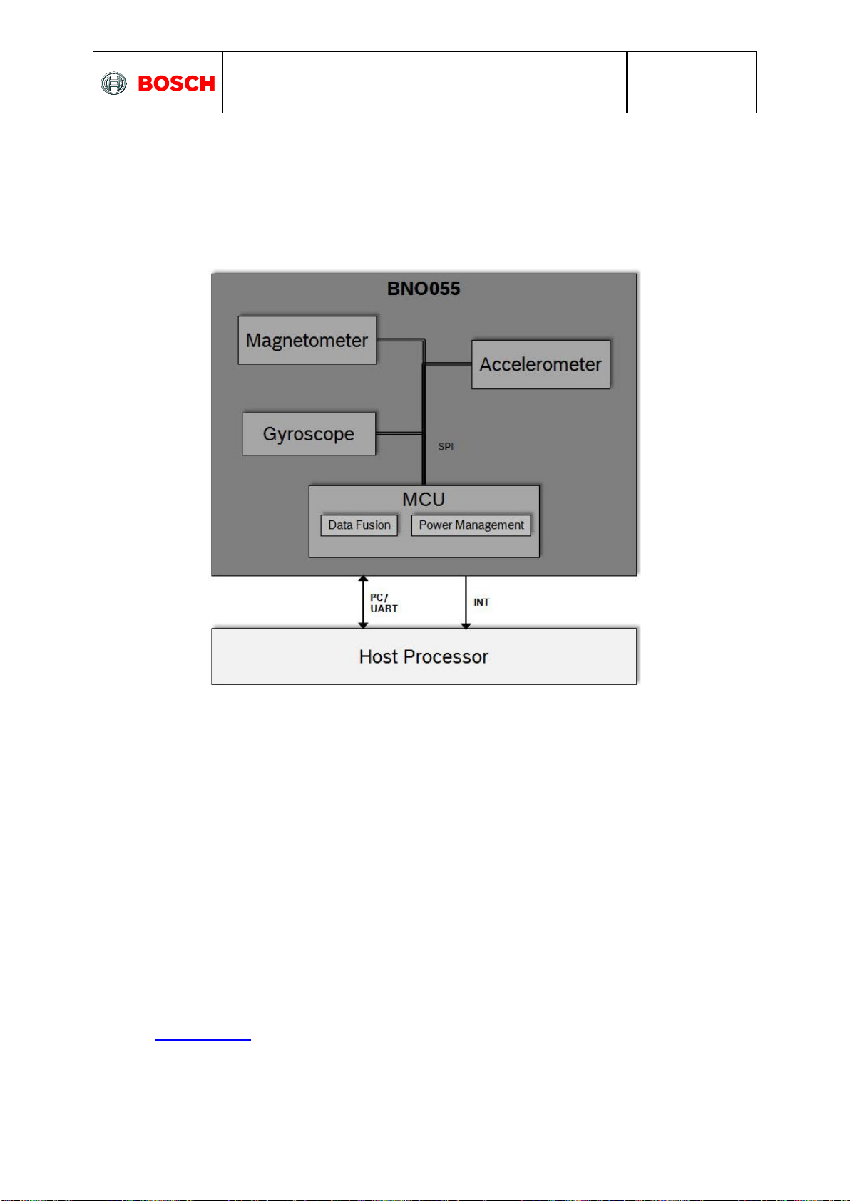
3.1 Architecture
The following figure shows the basic building blocks of the BNO055 device.
Figure 1: system architecture
3.2 Power management
The BNO055 has two distinct power supply pins:
• VDD is the main power supply for the internal sensors
• V
For the switching sequence of power supply VDD and VDDIO it is mandatory that VDD is powered
on and driven to the specified level before or at the same time as VDDIO is powered ON.
Otherwise there are no limitations on the voltage levels of both pins relative to each other, as
long as they are used within the specified operating range.
The sensor features a power-on reset (POR), initializing the register map with the default
values and starting in CONFIG mode. The POR is executed at every power on and can also
be triggered either by applying a low signal to the nRESET pin for at least 20ns or by setting
the RST_SYS bit in the SYS_TRIGGER register.
The BNO055 can be configured to run in one of the following power modes: normal mode,
low power mode, and suspend mode. These power modes are described in more detail in
section Power Modes
is a separate power supply pin used for the supply of the µC and the digital interfaces
DDIO
BST-BNO055-DS000-14 | Revision 1.4 | June 2016 Bosch Sensortec
© Bosch Sensortec GmbH reserves all rights even in the event of industrial property rights. We reserve all rights of disposal su ch as copying and passing on
to third parties. BOSCH and the symbol are registered trademarks of Robert Bosch GmbH, Germany.
Note: Specifications within this document are subject to change without notice.

BNO055
Data sheet
Page 19
Parameter
Value
[Reg Addr]: Reg Value
Power Mode
Normal Mode
[PWR_MODE]: xxxxxx00b
Low Power Mode
[PWR_MODE]: xxxxxx01b
Suspend Mode
[PWR_MODE]: xxxxxx10b
Description
Parameter
Value
Reg Value
Restriction
Entering to
sleep:
NO Motion
Interrupt
Detection
Type
No Motion
[ACC_NM_SET] : xxxxxxx1b
n/a
Detection Axis
[ACC_INT_Settings] : bit4-bit2
Shares common
bit with Any Motion
interrupt axis
selection
Params
Duration
[ACC_NM_SET] : bit6-bit1
n/a
Threshold
[ACC_NM_THRE] : bit7-bit0
n/a
Description
Parameter
Value
Reg Value
Waking up: Any
Motion Interrupt
Detection Type
Detection Axis
[ACC_INT_Settings] : bit4-bit2
Params
Duration
[ACC_INT_Settings] : bit1-bit0
Threshold
[ACC_AM_THRES] : bit7-bit0
Power Modes
The BNO055 support three different power modes: Normal mode, Low Power Mode, and
Suspend mode.
The power mode can be selected by writing to the PWR_MODE register as defined in the
table below. As default at start-up the BNO055 will run in Normal mode.
Table 3-1: power modes selection
3.2.1 Normal Mode
In normal mode all sensors required for the selected operating mode (see section 3.3) are
always switched ON. The register map and the internal peripherals of the MCU are always
operative in this mode.
3.2.2 Low Power Mode
If no activity (i.e. no motion) is detected for a configurable duration (default 5 seconds), the
BNO055 enters the low power mode. In this mode only the accelerometer is active. Once
motion is detected (i.e. the accelerometer signals an any-motion interrupt), the system is
woken up and normal mode is entered. The following settings are possible.
Table 3-2: Low power modes - Interrupts
Additionally, the interrupt pins can also be configured to provide HW interrupt to the host.
The BNO055 is by default configured to have optimum values for entering into sleep and
waking up. To restore these values, trigger system reset by setting RST_SYS bit in
SYS_TRIGGER register.
There are some limitations to achieve the low power mode performance:
Only No and Any motion interrupts are applicable and High-G and slow motion
interrupts are not applicable in low power mode.
Low power mode is not applicable where accelerometer is not employed.
BST-BNO055-DS000-14 | Revision 1.4 | June 2016 Bosch Sensortec
© Bosch Sensortec GmbH reserves all rights even in the event of industrial property rights. We reserve all rights of disposal su ch as copying and passing on
to third parties. BOSCH and the symbol are registered trademarks of Robert Bosch GmbH, Germany.
Note: Specifications within this document are subject to change without notice.

BNO055
Data sheet
Page 20
Operating Mode
Available sensor signals
Fusion Data
Accel
Mag
Gyro
Relative
orientation
Absolute
orientation
CONFIGMODE
- - - - -
Non
-fusion
modes
ACCONLY
X - - - -
MAGONLY
- X - - -
GYROONLY
- - X - -
ACCMAG
X X - - -
ACCGYRO
X - X - -
MAGGYRO
- X X - AMG
X X X - -
Fusion modes
IMU
X - X X -
COMPASS
X X - - X
M4G
X X X -
NDOF_FMC_OFF
X X X - X
NDOF
X X X - X
3.2.3 Suspend Mode
In suspend mode the system is paused and all the sensors and the microcontroller are put
into sleep mode. No values in the register map will be updated in this mode. To exit from
suspend mode the mode should be changed by writing to the PWR_MODE register (see
Table 3-1).
3.3 Operation Modes
The BNO055 provides a variety of output signals, which can be chosen by selecting the
appropriate operation mode. The table below lists the different modes and the available
sensor signals.
Table 3-3: Operating modes overview
The default operation mode after power-on is CONFIGMODE.
When the user changes to another operation mode, the sensors which are required in that
particular sensor mode are powered, while the sensors whose signals are not required are
set to suspend mode.
BST-BNO055-DS000-14 | Revision 1.4 | June 2016 Bosch Sensortec
© Bosch Sensortec GmbH reserves all rights even in the event of industrial property rights. We reserve all rights of disposal su ch as copying and passing on
to third parties. BOSCH and the symbol are registered trademarks of Robert Bosch GmbH, Germany.
Note: Specifications within this document are subject to change without notice.

BNO055
Data sheet
Page 21
Sensor
Range
Bandwidth
Accelerometer
4G
62.5 Hz
Magnetometer
NA
10 Hz
Gyroscope
2000 dps
32 Hz
Parameter
Value
[Reg Addr]: Reg Value
CONFIG MODE
CONFIGMODE
[OPR_MODE]: xxxx0000b
Non-Fusion
Mode
ACCONLY
[OPR_MODE]: xxxx0001b
MAGONLY
[OPR_MODE]: xxxx0010b
GYROONLY
[OPR_MODE]: xxxx0011b
ACCMAG
[OPR_MODE]: xxxx0100b
ACCGYRO
[OPR_MODE]: xxxx0101b
MAGGYRO
[OPR_MODE]: xxxx0110b
AMG
[OPR_MODE]: xxxx0111b
Fusion Mode
IMU
[OPR_MODE]: xxxx1000b
COMPASS
[OPR_MODE]: xxxx1001b
M4G
[OPR_MODE]: xxxx1010b
NDOF_FMC_OFF
[OPR_MODE]: xxxx1011b
NDOF
[OPR_MODE]: xxxx1100b
From
To
Switching time
CONFIGMODE
Any operation mode
7ms
Any operation mode
CONFIGMODE
19ms
The BNO055 sets the following default settings for the sensors. The user can overwrite these
settings in the register map when in CONFIGMODE.
Table 3-4: Default sensor settings
In any mode, the sensor data are available in the data register based on the unit selected.
The axis of the data is configured based on the axis-remap register configuration.
The operating mode can be selected by writing to the OPR_MODE register, possible register
values and the corresponding operating modes are shown in the table below.
Table 3-5: operating modes selection
Table 3-6 below shows the time required to switch between CONFIGMODE and the other
operating modes.
Table 3-6: Operating mode switching time
BST-BNO055-DS000-14 | Revision 1.4 | June 2016 Bosch Sensortec
© Bosch Sensortec GmbH reserves all rights even in the event of industrial property rights. We reserve all rights of disposal su ch as copying and passing on
to third parties. BOSCH and the symbol are registered trademarks of Robert Bosch GmbH, Germany.
Note: Specifications within this document are subject to change without notice.

BNO055
Data sheet
Page 22
3.3.1 Config Mode
This mode is used to configure BNO, wherein all output data is reset to zero and sensor
fusion is halted. This is the only mode in which all the writable register map entries can be
changed. (Exceptions from this rule are the interrupt registers (INT and INT_MSK) and the
operation mode register (OPR_MODE), which can be modified in any operation mode.)
As being said, this mode is the default operation mode after power-on or RESET. Any other
mode must be chosen to be able to read any sensor data.
3.3.2 Non-Fusion Modes
3.3.2.1 ACCONLY
If the application requires only raw accelerometer data, this mode can be chosen. In this
mode the other sensors (magnetometer, gyro) are suspended to lower the power
consumption. In this mode, the BNO055 behaves like a stand-alone acceleration sensor.
3.3.2.1 MAGONLY
In MAGONLY mode, the BNO055 behaves like a stand-alone magnetometer, with
acceleration sensor and gyroscope being suspended.
3.3.2.2 GYROONLY
In GYROONLY mode, the BNO055 behaves like a stand-alone gyroscope, with acceleration
sensor and magnetometer being suspended.
3.3.2.3 ACCMAG
Both accelerometer and magnetometer are switched on, the user can read the data from
these two sensors.
3.3.2.4 ACCGYRO
Both accelerometer and gyroscope are switched on; the user can read the data from these
two sensors.
3.3.2.5 MAGGYRO
Both magnetometer and gyroscope are switched on, the user can read the data from these
two sensors.
3.3.2.6 AMG (ACC-MAG-GYRO)
All three sensors accelerometer, magnetometer and gyroscope are switched on.
3.3.3 Fusion modes
Sensor fusion modes are meant to calculate measures describing the orientation of the
device in space. It can be distinguished between non-absolute or relative orientation and
absolute orientation. Absolute orientation means orientation of the sensor with respect to the
earth and its magnetic field. In other words, absolute orientation sensor fusion modes
calculate the direction of the magnetic north pole.
In non-absolute or relative orientation modes, the heading of the sensor can vary depending
on how the sensor is placed initially.
All fusion modes provide the heading of the sensor as quaternion data or in Euler angles
(roll, pitch and yaw angle). The acceleration sensor is both exposed to the gravity force and
to accelerations applied to the sensor due to movement. In fusion modes it is possible to
separate the two acceleration sources, and thus the sensor fusion data provides separately
linear acceleration (i.e. acceleration that is applied due to movement) and the gravity vector.
BST-BNO055-DS000-14 | Revision 1.4 | June 2016 Bosch Sensortec
© Bosch Sensortec GmbH reserves all rights even in the event of industrial property rights. We reserve all rights of disposal su ch as copying and passing on
to third parties. BOSCH and the symbol are registered trademarks of Robert Bosch GmbH, Germany.
Note: Specifications within this document are subject to change without notice.

BNO055
Data sheet
Page 23
3.3.3.1 IMU (Inertial Measurement Unit)
In the IMU mode the relative orientation of the BNO055 in space is calculated from the
accelerometer and gyroscope data. The calculation is fast (i.e. high output data rate).
3.3.3.2 COMPASS
The COMPASS mode is intended to measure the magnetic earth field and calculate the
geographic direction.
The earth magnetic field is a vector with the horizontal components x,y and the vertical z
component. It depends on the position on the globe and natural iron occurrence. For heading
calculation (direction of compass pointer) only the horizontal components x and y are used.
Therefore the vector components of the earth magnetic field must be transformed in the
horizontal plane, which requires the knowledge of the direction of the gravity vector. To
summarize, the heading can only be calculated when considering gravity and magnetic field
at the same time.
However, the measurement accuracy depends on the stability of the surrounding magnetic
field. Furthermore, since the earth magnetic field is usually much smaller than the magnetic
fields that occur around and inside electronic devices, the compass mode requires calibration
(see chapter 3.10)
3.3.3.3 M4G (Magnet for Gyroscope)
The M4G mode is similar to the IMU mode, but instead of using the gyroscope signal to
detect rotation, the changing orientation of the magnetometer in the magnetic field is used.
Since the magnetometer has much lower power consumption than the gyroscope, this mode
is less power consuming in comparison to the IMU mode. There are no drift effects in this
mode which are inherent to the gyroscope.
However, as for compass mode, the measurement accuracy depends on the stability of the
surrounding magnetic field.
For this mode no magnetometer calibration is required and also not available.
3.3.3.4 NDOF_FMC_OFF
This fusion mode is same as NDOF mode, but with the Fast Magnetometer Calibration
turned ‘OFF’.
3.3.3.5 NDOF
This is a fusion mode with 9 degrees of freedom where the fused absolute orientation data is
calculated from accelerometer, gyroscope and the magnetometer. The advantages of
combining all three sensors are a fast calculation, resulting in high output data rate, and high
robustness from magnetic field distortions. In this mode the Fast Magnetometer calibration is
turned ON and thereby resulting in quick calibration of the magnetometer and higher output
data accuracy. The current consumption is slightly higher in comparison to the
NDOF_FMC_OFF fusion mode.
BST-BNO055-DS000-14 | Revision 1.4 | June 2016 Bosch Sensortec
© Bosch Sensortec GmbH reserves all rights even in the event of industrial property rights. We reserve all rights of disposal su ch as copying and passing on
to third parties. BOSCH and the symbol are registered trademarks of Robert Bosch GmbH, Germany.
Note: Specifications within this document are subject to change without notice.

BNO055
Data sheet
Page 24
Bit 7
Bit 6
Bit 5
Bit 4
Bit 3
Bit 2
Bit 1
Bit 0
Reserved
Remapped Z axis value
Remapped Y axis
value
Remapped X axis
value
Value
Axis Representation
00
X - Axis
01
Y - Axis
10
Z- Axis
11
Invalid
Bit 7
Bit 6
Bit 5
Bit 4
Bit 3
Bit 2
Bit 1
Bit 0
Reserved
Remapped
X axis sign
Remapped
Y axis sign
Remapped
Z axis sign
Value
Sign
0
Positive
1
Negative
Z; Ωz; z
X; Ωx; x
Y; Ωy; y
Accel; Gyro; Magnet
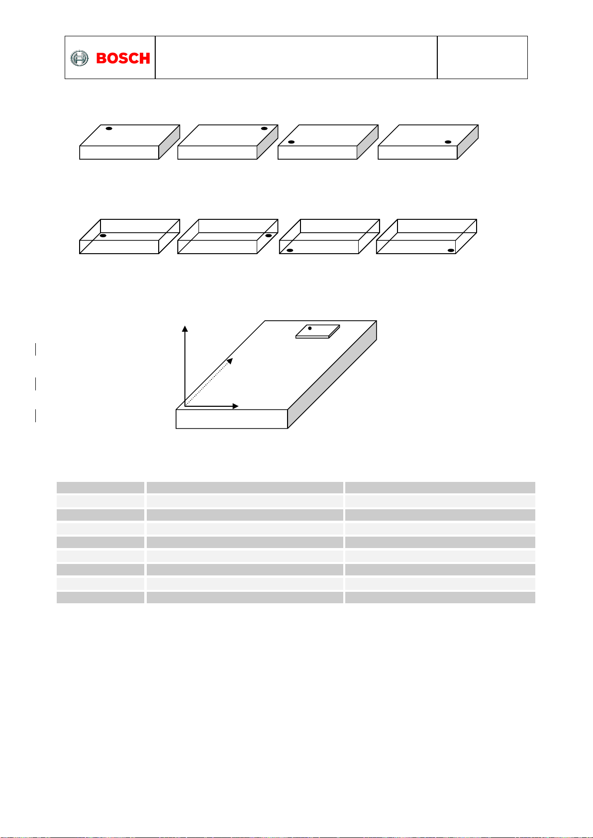
3.4 Axis remap
The device mounting position should not limit the data output of the BNO055 device. The
axis of the device can be re-configured to the new reference axis.
Axis configuration byte: Register Address: AXIS_MAP_CONFIG
There are two bits are used to configure the axis remap which will define in the following
way,
Also, when user try to configure the same axis to two or more then BNO055 will take this as
invalid condition and previous configuration will be restored in the register map. The default
value is: X Axis = X, Y Axis = Y and Z Axis = Z (AXIS_REMAP_CONFIG = 0x24).
Axis sign configuration byte: Register Address: AXIS_MAP_SIGN
The default value is 0x00.
The default values correspond to the following coordinate system
BST-BNO055-DS000-14 | Revision 1.4 | June 2016 Bosch Sensortec
© Bosch Sensortec GmbH reserves all rights even in the event of industrial property rights. We reserve all rights of disposal su ch as copying and passing on
to third parties. BOSCH and the symbol are registered trademarks of Robert Bosch GmbH, Germany.
Note: Specifications within this document are subject to change without notice.
BNO055
Data sheet
Page 25
Placement
AXIS_REMAP_CONFIG
AXIS_REMAP_SIGN
P0
0x21
0x04
P1 (default)
0x24
0x00
P2
0x24
0x06
P3
0x21
0x02
P4
0x24
0x03
P5
0x21
0x01
P6
0x21
0x07
P7
0x24
0x05
TOP VIEW
BOTTOM VIEW
ZYX
P0
P1
P2
P3
P4
P5
P6
P7
P0
Some example placement for axis vs. register settings:
For the above described placements, following would be the axis configuration parameters.
BST-BNO055-DS000-14 | Revision 1.4 | June 2016 Bosch Sensortec
© Bosch Sensortec GmbH reserves all rights even in the event of industrial property rights. We reserve all rights of disposal su ch as copying and passing on
to third parties. BOSCH and the symbol are registered trademarks of Robert Bosch GmbH, Germany.
Note: Specifications within this document are subject to change without notice.

BNO055
Data sheet
Page 26
Sensors
Parameters
Value
Accelerometer
Power Mode
NORMAL
Range
+/- 4g
Bandwidth
62.5Hz
Resolution
14 bits
Gyroscope
Power Mode
NORMAL
Range
2000 °/s
Bandwidth
32Hz
Resolution
16 bits
Magnetometer
Power Mode
FORCED
ODR
20Hz
XY Repetition
15
Z Repetition
16
Resolution x/y/z
13/13/15 bits
3.5 Sensor Configuration
The fusion outputs of the BNO055 are tightly linked with the sensor configuration settings.
Due to this fact, the sensor configuration is limited when BNO055 is configured to run in any
of the fusion operating mode. In any of the non-fusion modes the configuration settings can
be updated by writing to the configuration registers as defined in the following sections.
3.5.1 Default sensor configuration
At power-on the sensors are configured with the default settings as defined in Table 3-8
below.
Table 3-7: Default sensor configuration at power-on
BST-BNO055-DS000-14 | Revision 1.4 | June 2016 Bosch Sensortec
© Bosch Sensortec GmbH reserves all rights even in the event of industrial property rights. We reserve all rights of disposal su ch as copying and passing on
to third parties. BOSCH and the symbol are registered trademarks of Robert Bosch GmbH, Germany.
Note: Specifications within this document are subject to change without notice.

BNO055
Data sheet
Page 27
Parameter
Values
[Reg Addr]: Reg Value
Restrictions
G Range
2G
[ACC_Config]: xxxxxx00b
Auto controlled in fusion
mode
4G
[ACC_Config]: xxxxxx01b
8G
[ACC_Config]: xxxxxx10b
16G
[ACC_Config]: xxxxxx11b
Bandwidth
7.81Hz
[ACC_Config]: xxx000xxb
15.63Hz
[ACC_Config]: xxx001xxb
31.25Hz
[ACC_Config]: xxx010xxb
62.5Hz
[ACC_Config]: xxx011xxb
125Hz
[ACC_Config]: xxx100xxb
250Hz
[ACC_Config]: xxx101xxb
500Hz
[ACC_Config]: xxx110xxb
1000Hz
[ACC_Config]: xxx111xxb
Operation Mode
Normal
[ACC_Config]: 000xxxxxb
Suspend
[ACC_Config]: 001xxxxxb
Low Power 1
[ACC_Config]: 010xxxxxb
Standby
[ACC_Config]: 011xxxxxb
Low Power 2
[ACC_Config]: 100xxxxxb
Deep Suspend
[ACC_Config]: 101xxxxxb
3.5.2 Accelerometer configuration
The fusion outputs of the BNO055 are tightly linked with the accelerometer sensor settings.
Therefore the configuration possibilities are restricted when running in any of the fusion
operating modes. The accelerometer configuration can be changed by writing to the
ACC_Config register, Table below shows different Accelerometer configurations
Table 3-8: Accelerometer configurations
The accelerometer sensor operation mode is not configurable by user when BNO power
mode is configured as low power mode. BNO rewrites the user configured value to Normal
mode when switching from config mode to any BNO operation mode. This used to achieve
the BNO low power mode performance.
BST-BNO055-DS000-14 | Revision 1.4 | June 2016 Bosch Sensortec
© Bosch Sensortec GmbH reserves all rights even in the event of industrial property rights. We reserve all rights of disposal su ch as copying and passing on
to third parties. BOSCH and the symbol are registered trademarks of Robert Bosch GmbH, Germany.
Note: Specifications within this document are subject to change without notice.

BNO055
Data sheet
Page 28
Parameter
Values
[Reg Addr]: Register value
Restrictions
Range
2000 dps
[GYR_Config_0]: xxxxx000b
Auto controlled in fusion mode
1000 dps
[GYR_Config_0]: xxxxx001b
500dps
[GYR_Config_0]: xxxxx010b
250 dps
[GYR_Config_0]: xxxxx011b
125 dps
[GYR_Config_0]: xxxxx100b
Bandwidth
523Hz
[GYR_Config_0]: xx000xxxb
230Hz
[GYR_Config_0]: xx001xxxb
116Hz
[GYR_Config_0]: xx010xxxb
47Hz
[GYR_Config_0]: xx011xxxb
23Hz
[GYR_Config_0]: xx100xxxb
12Hz
[GYR_Config_0]: xx101xxxb
64Hz
[GYR_Config_0]: xx110xxxb
32Hz
[GYR_Config_0]: xx111xxxb
Operation Mode
Normal
[GYR_Config_1]: xxxxx000b
Fast Power up
[GYR_Config_1]: xxxxx001b
Deep Suspend
[GYR_Config_1]: xxxxx010b
Suspend
[GYR_Config_1]: xxxxx011b
Advanced
Powersave
[GYR_Config_1]: xxxxx100b
3.5.3 Gyroscope configuration
The fusion outputs of the BNO055 are tightly linked with the angular rate sensor settings.
Therefore the configuration possibilities are restricted when running in any of the fusion
operating modes. The gyroscope configuration can be changed by writing to the GYR_Config
register, Table below shows different Gyroscope configurations
Table 3-9: Gyroscope configurations
BST-BNO055-DS000-14 | Revision 1.4 | June 2016 Bosch Sensortec
© Bosch Sensortec GmbH reserves all rights even in the event of industrial property rights. We reserve all rights of disposal su ch as copying and passing on
to third parties. BOSCH and the symbol are registered trademarks of Robert Bosch GmbH, Germany.
Note: Specifications within this document are subject to change without notice.

BNO055
Data sheet
Page 29
Parameter
Values
[Reg Addr]: Register
value
Restrictions
Data output rate
2Hz
[MAG_Config]: xxxxx000b
Auto controlled in fusion mode
6Hz
[MAG_Config]: xxxxx001b
8Hz
[MAG_Config]: xxxxx010b
10Hz
[MAG_Config]: xxxxx011b
15Hz
[MAG_Config]: xxxxx100b
20Hz
[MAG_Config]: xxxxx101b
25Hz
[MAG_Config]: xxxxx110b
30Hz
[MAG_Config]: xxxxx111b
Operation Mode
Low Power
[MAG_Config]: xxx00xxxb
Regular
[MAG_Config]: xxx01xxxb
Enhanced
Regular
[MAG_Config]: xxx10xxxb
High Accuracy
[MAG_Config]: xxx11xxxb
Power Mode
Normal
[MAG_Config]: x00xxxxxb
Sleep
[MAG_Config]: x01xxxxxb
Suspend
[MAG_Config]: x10xxxxxb
Force Mode
[MAG_Config]: x11xxxxxb
3.5.4 Magnetometer configuration
The fusion outputs of the BNO055 are tightly linked with the magnetometer sensor settings.
Therefore the configuration possibilities are restricted when running in any of the fusion
operating modes. The magnetometer configuration can be changed by writing to the
MAG_Config register, Table below shows different Magnetometer configurations.
Table 3-10: Magnetometer configurations
BST-BNO055-DS000-14 | Revision 1.4 | June 2016 Bosch Sensortec
© Bosch Sensortec GmbH reserves all rights even in the event of industrial property rights. We reserve all rights of disposal su ch as copying and passing on
to third parties. BOSCH and the symbol are registered trademarks of Robert Bosch GmbH, Germany.
Note: Specifications within this document are subject to change without notice.

BNO055
Data sheet
Page 30
Data
Units
[Reg Addr]: Register Value
Acceleration, Linear
Acceleration, Gravity
vector
m/s2
[UNIT_SEL] : xxxxxxx0b
mg
[UNIT_SEL] : xxxxxxx1b
Magnetic Field Strength
Micro Tesla
NA
Angular Rate
Dps
[UNIT_SEL] : xxxxxx0xb
Rps
[UNIT_SEL] : xxxxxx1xb
Euler Angles
Degrees
[UNIT_SEL] : xxxxx0xxb
Radians
[UNIT_SEL] : xxxxx1xxb
Quaternion
Quaternion
units
NA
Temperature
°C
[UNIT_SEL] : xxx0xxxxb
°F
[UNIT_SEL] : xxx1xxxxb
Parameter
Values
[Reg Addr]: Register value
Fusion data output
format
Windows
[UNIT_SEL]: 0xxxxxxxb
Android
[UNIT_SEL]: 1xxxxxxxb
Rotation angle
Range (Android format)
Range (Windows format)
Pitch
+180° to -180° (turning
clockwise decreases values)
-180° to +180° (turning clockwise increases values)
Roll
-90° to +90° (increasing with increasing inclination)
Heading / Yaw
0° to 360° (turning clockwise increases values)
3.6 Output data
Depending on the selected operating mode the device will output either un-calibrated sensor
data (in non-fusion mode) or calibrated / fused data (in fusion mode), this section describes
the output data for each modes.
3.6.1 Unit selection
The measurement units for the various data outputs (regardless of operation mode) can be
configured by writing to the UNIT_SEL register as described in Table 3-9.
Table 3-11: unit selection
3.6.2 Data output format
The data output format can be selected by writing to the UNIT_SEL register, this allows user
to switch between the orientation definition described by Windows and Android operating
systems.
Table 3-12: Fusion data output format
The output data format is based on the following convention regarding the rotation angles for
roll, pitch and heading / yaw (compare also section 3.4):
Table 3-13: Rotation angle conventions
BST-BNO055-DS000-14 | Revision 1.4 | June 2016 Bosch Sensortec
© Bosch Sensortec GmbH reserves all rights even in the event of industrial property rights. We reserve all rights of disposal su ch as copying and passing on
to third parties. BOSCH and the symbol are registered trademarks of Robert Bosch GmbH, Germany.
Note: Specifications within this document are subject to change without notice.
 Loading...