


MARK V 111-H

MARK V SERIES
CONVECTION OVEN
SERVICE AND REPAIR MANUAL
BLODGETT OVEN COMPANY
www.blodgett.com
44 Lakeside Avenue, Burlington, Vermont 05401 USA Telephone (802) 658Ć6600 Fax: (802)864Ć0183
PN 33144 Rev F (7/02)
E 2002 - G.S. Blodgett Corporation All rights reserved.
Duplication of the information in this manual is prohibited without the consent of the Blodgett Service Department.

TABLE OF CONTENTS
i
1. INTRODUCTION
Oven Specifications 1-1. . . . . . . . . . . . . . . . . . . . . . . . . . . . . . . . . . . . . . . . . . . . . . . . . . . . . . . . . . . . . . .
2. OPERATION
Sequence of Operations 2-1. . . . . . . . . . . . . . . . . . . . . . . . . . . . . . . . . . . . . . . . . . . . . . . . . . . . . . . . . . .
Cook Only - 18459 Rev D 2-1. . . . . . . . . . . . . . . . . . . . . . . . . . . . . . . . . . . . . . . . . . . . . . . . . . . . .
CE Approved Cook Only - 33339 Rev C 2-3. . . . . . . . . . . . . . . . . . . . . . . . . . . . . . . . . . . . . . . . .
Cook and Hold - 18791 2-5. . . . . . . . . . . . . . . . . . . . . . . . . . . . . . . . . . . . . . . . . . . . . . . . . . . . . . .
Solid State Digital - 30070 Rev B 2-8. . . . . . . . . . . . . . . . . . . . . . . . . . . . . . . . . . . . . . . . . . . . . . .
CE Approved Solid State Digital - 33345 Rev C 2-10. . . . . . . . . . . . . . . . . . . . . . . . . . . . . . . . . .
Fan Delay with Pulse Plus - 18466 Rev D 2-12. . . . . . . . . . . . . . . . . . . . . . . . . . . . . . . . . . . . . . . .
Humidaire - 1846 Rev M 2-14. . . . . . . . . . . . . . . . . . . . . . . . . . . . . . . . . . . . . . . . . . . . . . . . . . . . . .
Intellihold and Intelliplus - 22027 Rev A 2-17. . . . . . . . . . . . . . . . . . . . . . . . . . . . . . . . . . . . . . . . .
Intellitouch - 19361 Rev A 2-19. . . . . . . . . . . . . . . . . . . . . . . . . . . . . . . . . . . . . . . . . . . . . . . . . . . . .
Blodgett IQ Control - 33078 Rev A 2-21. . . . . . . . . . . . . . . . . . . . . . . . . . . . . . . . . . . . . . . . . . . . . .
3. CALIBRATION AND ADJUSTMENT
Doors 3-1. . . . . . . . . . . . . . . . . . . . . . . . . . . . . . . . . . . . . . . . . . . . . . . . . . . . . . . . . . . . . . . . . . . . . . . . . . .
Door Blower Switch 3-2. . . . . . . . . . . . . . . . . . . . . . . . . . . . . . . . . . . . . . . . . . . . . . . . . . . . . . . . . . . . . . .
Thermostat 3-2. . . . . . . . . . . . . . . . . . . . . . . . . . . . . . . . . . . . . . . . . . . . . . . . . . . . . . . . . . . . . . . . . . . . . .
Solid State Manual 3-4. . . . . . . . . . . . . . . . . . . . . . . . . . . . . . . . . . . . . . . . . . . . . . . . . . . . . . . . . . . . . . . .
Solid State Digital Control 3-6. . . . . . . . . . . . . . . . . . . . . . . . . . . . . . . . . . . . . . . . . . . . . . . . . . . . . . . . . .
Intellihold and Intelliplus Controls 3-7. . . . . . . . . . . . . . . . . . . . . . . . . . . . . . . . . . . . . . . . . . . . . . . . . . .
Intellitouch Control 3-8. . . . . . . . . . . . . . . . . . . . . . . . . . . . . . . . . . . . . . . . . . . . . . . . . . . . . . . . . . . . . . . .
Intellitouch II Control 3-9. . . . . . . . . . . . . . . . . . . . . . . . . . . . . . . . . . . . . . . . . . . . . . . . . . . . . . . . . . . . . .
Blodgett IQ Control 3-10. . . . . . . . . . . . . . . . . . . . . . . . . . . . . . . . . . . . . . . . . . . . . . . . . . . . . . . . . . . . . . .
Blodgett IQ2T Control Factory Level Programming 3-12. . . . . . . . . . . . . . . . . . . . . . . . . . . . . . . . . . .
IQ VVCĆ208 Control 3-13. . . . . . . . . . . . . . . . . . . . . . . . . . . . . . . . . . . . . . . . . . . . . . . . . . . . . . . . . . . . . . .
Probe Resistance vs Heating Elements 3-18. . . . . . . . . . . . . . . . . . . . . . . . . . . . . . . . . . . . . . . . . . . . . .
Probe Resistance vs Temperature 3-18. . . . . . . . . . . . . . . . . . . . . . . . . . . . . . . . . . . . . . . . . . . . . . . . . .
4. TROUBLESHOOTING
Heat System 4-1. . . . . . . . . . . . . . . . . . . . . . . . . . . . . . . . . . . . . . . . . . . . . . . . . . . . . . . . . . . . . . . . . . . . .
Display Error Codes 4-3. . . . . . . . . . . . . . . . . . . . . . . . . . . . . . . . . . . . . . . . . . . . . . . . . . . . . . . . . . . . . .
Intellitouch 4-3. . . . . . . . . . . . . . . . . . . . . . . . . . . . . . . . . . . . . . . . . . . . . . . . . . . . . . . . . . . . . . . . . . .
Intellihold and Intelliplus 4-3. . . . . . . . . . . . . . . . . . . . . . . . . . . . . . . . . . . . . . . . . . . . . . . . . . . . . . .
Blodgett IQ Control 4-3. . . . . . . . . . . . . . . . . . . . . . . . . . . . . . . . . . . . . . . . . . . . . . . . . . . . . . . . . . . .

TABLE OF CONTENTS
ii
5. PARTS REPLACEMENT
Door Assembly 5-1. . . . . . . . . . . . . . . . . . . . . . . . . . . . . . . . . . . . . . . . . . . . . . . . . . . . . . . . . . . . . . . . . . .
Door 5-1. . . . . . . . . . . . . . . . . . . . . . . . . . . . . . . . . . . . . . . . . . . . . . . . . . . . . . . . . . . . . . . . . . . . . . . .
Door Arm Support Assembly 5-1. . . . . . . . . . . . . . . . . . . . . . . . . . . . . . . . . . . . . . . . . . . . . . . . . . .
Window Assembly 5-2. . . . . . . . . . . . . . . . . . . . . . . . . . . . . . . . . . . . . . . . . . . . . . . . . . . . . . . . . . . .
Compartment Liner Bottom 5-2. . . . . . . . . . . . . . . . . . . . . . . . . . . . . . . . . . . . . . . . . . . . . . . . . . . . . . . .
Motor and Blower Assembly 5-3. . . . . . . . . . . . . . . . . . . . . . . . . . . . . . . . . . . . . . . . . . . . . . . . . . . . . . .
Blower Wheel 5-3. . . . . . . . . . . . . . . . . . . . . . . . . . . . . . . . . . . . . . . . . . . . . . . . . . . . . . . . . . . . . . . . .
Motor 5-3. . . . . . . . . . . . . . . . . . . . . . . . . . . . . . . . . . . . . . . . . . . . . . . . . . . . . . . . . . . . . . . . . . . . . . . .
Electrical Components 5-4. . . . . . . . . . . . . . . . . . . . . . . . . . . . . . . . . . . . . . . . . . . . . . . . . . . . . . . . . . . .
Bulb and Capillary Thermostat 5-4. . . . . . . . . . . . . . . . . . . . . . . . . . . . . . . . . . . . . . . . . . . . . . . . . .
Electrical Components Located in the Control Module 5-4. . . . . . . . . . . . . . . . . . . . . . . . . . . . .
Door Switch 5-4. . . . . . . . . . . . . . . . . . . . . . . . . . . . . . . . . . . . . . . . . . . . . . . . . . . . . . . . . . . . . . . . . .

INTRODUCTION
CHAPTER 1
MARK V
1-1
OVEN SPECIFICATIONS
ELECTRICAL SPECIFICATIONS
Installations within the U.S. and Canada
Single phase models require a 60 Hz,
208/240VAC, 3 wire service consisting of L1, L2
and ground. Three phase models require a 60 Hz,
208/240/440/480, 4 wire service consisting of L1,
L2, L3 and ground. Wiring from the power source
to any of the single phase units must be a minimum
of #6 AWG copper stranded wire. Wiring from the
power source to the 208/240 three phase units
must be a minimum of #8 AWG copper stranded
wire. Wiring from the power source to the 440/480
three phase units must be a minimum of #12 AWG
copper stranded wire.
General Export Installations
Single phase models require a 50 Hz,
220/240VAC, 3 wire service consisting of L1, L2
and ground. Three phase models require a 50 Hz,
415/240 or 380/220 VAC, 5 wire service consisting
of L1, L2, L3, neutral and ground. Use 90_C wire
and size according to local codes.
CE approved installations
Single phase models require a 50 Hz, 230VAC 3
wire service consisting of L1, neutral and ground.
Three phase models require a 50 Hz, 400/230VAC,
5 wire service consisting of L1, L2, L3, neutral and
ground. Use 90_C wire and size according to local
codes.
ELECTRICAL SPECIFICATIONS (per section)
KW Hz Volts Phase
Amps
Electrical Connection
L1 L2 L3 N
(minimum size)
U.S. and Canadian installations
11.0 60 208 1 51 - 51 - 6 AWG
11.0 60 208 3 31 29 29 - 8 AWG
11.0 60 220Ć240 1 44 - 44 - 6 AWG
11.0 60 220Ć240 3 26 24 24 - 8 AWG
11.0 60 440 3 15 14 14 - 12 AWG
11.0 60 480 3 14 13 13 - 12 AWG
General Export installations
11.0 50 208 3 18 18 18 4 Size per local code
11.0 50 220Ć240 1 48 - - 48 Size per local code
11.0 50 220/380 3 18 16 16 2 Size per local code
11.0 50 240/415 3 18 14 14 4 Size per local code
11.0 50 230/400 3 18 15 15 3 Size per local code
CE installations
11.0 50 400 3N 18 15 15 3 Size per local code

OPERATION
CHAPTER 2

MARK V
2-1
SEQUENCE OF OPERATIONS
NOTE: The following instructions represent the most common controllers. For questions regarding other
options call the Blodgett Service Department at (800)331Ć5842.
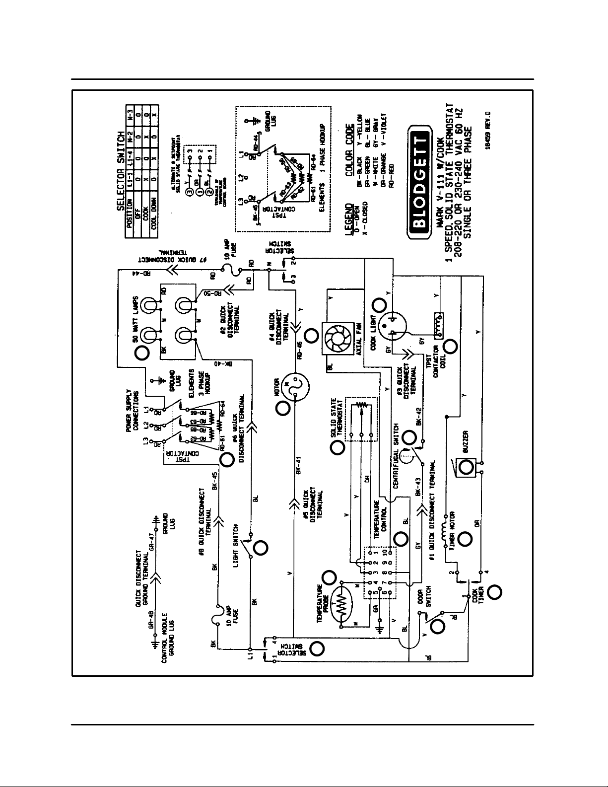
COOK ONLY - 18459 REV D
Component Reference
NOTE: Refer to FIGURE 1 page 2-2 for compoĆ
nent locations.
1. MODE SELECTOR SWITCH
2. COOK TIMER
3. DOOR SWITCH
4. TEMPERATURE CONTROL BOARD
5. AXIAL FAN
6. CONV ECTION FAN MOTOR
7. TEMPERATURE PROBE
8. SOLID STATE POTENTIOMETER
9. CENTRIFUGAL SWITCH
10. COOK LIGHT
11. ELEMENT CONTACTOR
12. HEATING ELEMENTS
13. 50 WATT LAMPS
14. LIGHT SWITCH
15. TIMER MOTOR
16. BUZZER
Operation
1. Turn the mode selector switch (1) to the cook
position. Power goes to terminal #1 of the
cook timer (2), one side of the door switch (3),
terminal #8 of the temperature control board
(4) and the axial fan (5).
2. If the doors are closed the door switch (3)
should also be closed sending power to termiĆ
nal #6 of the temperature control board (4)
and to the convection fan motor (6).
NOTE: This motor has a built in centrifugal
switch (9) that closes when the motor
reaches full speed. If found faulty do
not bypass, the whole motor should be
replaced.
3. On a call for heat from the temperature control
circuit, a circuit is completed between termiĆ
nals #6 and #7 of the temperature control
board (4).
NOTE: The temperature control circuit conĆ
sists of the temperature probe (7), the
temperature control board (4) and the
solid state potentiometer (8).
Power is sent out of terminal #7 to one side of
the centrifugal switch (9). If the convection fan
motor (6) is at full speed the centrifugal switch
(9) closes sending power to the cook light (10)
and one side of the element contactor (11).
When the contactor closes the heating eleĆ
ments (12) power up.
4. The 50 watt lamps (13) only receive power when
the light switch (14) is activated. These lamps
are 115 volt and are wired in series parallel.
5. When the cook timer (2) is set for a time a cirĆ
cuit is made between terminals #1 and #2
powering up the timer motor (15). At the expiĆ
ration of the set time the switch in the cook timĆ
er (2) toggles from 1-2 to 1-4 powering up
the buzzer (16).
NOTE: Put the timer in the home position to siĆ
lence the buzzer.
NOTE: Turn the mode selector switch to cool
down to bypass the door microswitch. This
allows the convection fan motor to operate
even when the doors are open.
NOTE: This oven may be converted from single to
three phase, however, contactors must be
changed due to the difference in amp
draw. Reference detail inset in FIGURE 1.
NOTE: The resistive values for the probes used in
this oven have descending temperature
coefficients. As the temperature increases
the resistive values decrease.
NOTE: Reference page 4-2 of the TroubleshootĆ
ing section for the resistive values of the
heating elements. The reading should be
taken in a cold state.
OPERATION
2-2
1
2
3
4
15
16
9
8
7
14
6
12
13
5
10
11
FIGURE 1

MARK V
2-3
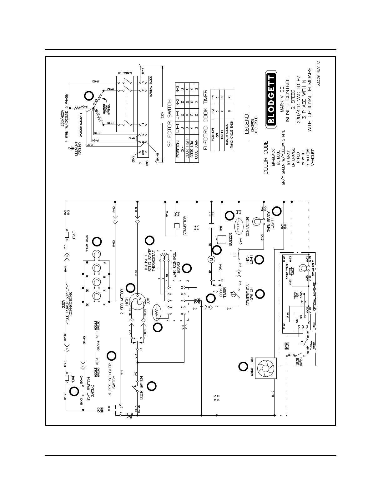
CE APPROVED COOK ONLY - 33339 REV C
Component Reference
NOTE: Refer to FIGURE 2 page 2-4 for compoĆ
nent locations.
1. MODE SELECTOR SWITCH
2. COOK TIMER
3. DOOR SWITCH
4. TEMPERATURE CONTROL BOARD
5. AXIAL FAN
6. CONVECTION FAN MOTOR
7. TEMPERATURE PROBE
8. SOLID STATE POTENTIOMETER
9. CENTRIFUGAL SWITCH
10. HIGH LIMIT SWITCH
11. ELEMENT CONTACTOR
12. COOK LIGHT
13. HEATING ELEMENTS
14. 50 WATT LAMPS
15. LIGHT SWITCH
16. TIMER MOTOR
17. BUZZER
Operation
1. Turn the mode selector switch (1) to the cook
position. Power goes to terminal #1 of the
cook timer (2), one side of the door switch (3),
terminal #8 of the temperature control board
(4) and the axial fan (5).
2. If the doors are closed the door switch (3)
should also be closed sending power to termiĆ
nal #6 of the temperature control board (4)
and to the convection fan motor (6).
NOTE: This motor has a built in centrifugal
switch (9) that closes when the motor
reaches full speed. If found faulty do
not bypass, the whole motor should be
replaced.
3. On a call for heat from the temperature control
circuit, a circuit is completed between termiĆ
nals #6 and #7 of the temperature control
board (4).
NOTE: The temperature control circuit conĆ
sists of the temperature probe (7), the
temperature control board (4) and the
solid state potentiometer (8).
Power is sent out of terminal #7 to one side of
the centrifugal switch (9). If the convection fan
motor (6) is at full speed the centrifugal switch
(9) closes sending power to one side of a high
limit switch (10), if the high limit is closed then
power will be sent to one side of the contactor
(11) and an indicator light (12). When the conĆ
tactor closes the heating elements (12) power
up.
4. The 50 watt lamps (13) only receive power when
the light switch (14) is activated.
5. When the cook timer (2) is set for a time a cirĆ
cuit is made between terminals #1 and #2
powering up the timer motor (15). At the expiĆ
ration of the set time the switch in the cook timĆ
er (2) toggles from 1-2 to 1-4 powering up
the buzzer (16).
NOTE: Put the timer in the home position to siĆ
lence the buzzer.
NOTE: Turn the mode selector switch to cool
down to bypass the door microswitch. This
allows the convection fan motor to operate
even when the doors are open.
NOTE: This oven may be converted from single to
three phase, however, contactors must be
changed due to the difference in amp
draw. Reference detail inset in FIGURE 2.
NOTE: Reference page 4-2 of the TroubleshootĆ
ing section for the resistive values of the
heating elements. The reading should be
taken in a cold state.
OPERATION
2-4
1
15
3
6
14
4
2
17
11
12
10
9
5
13
7
8
FIGURE 2

MARK V
2-5
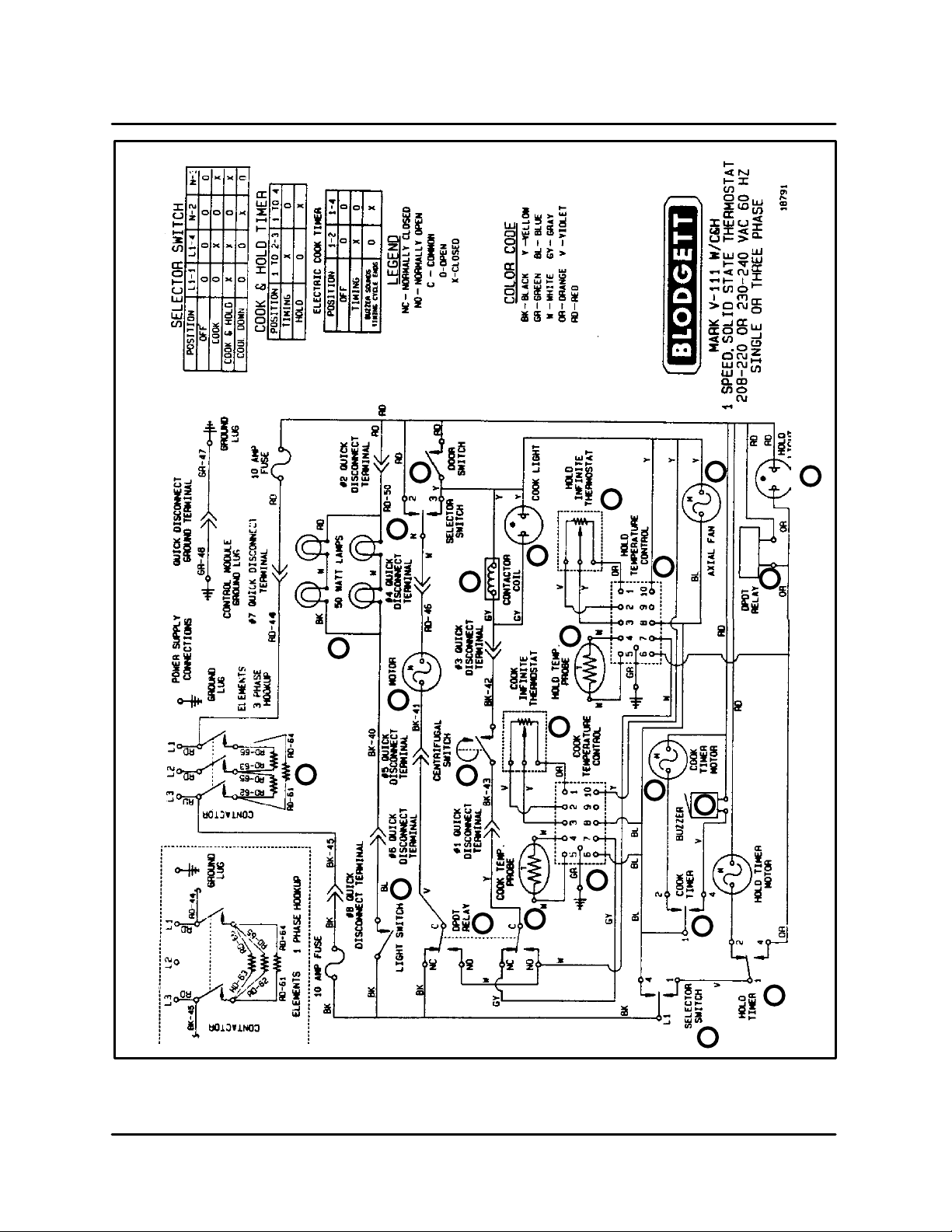
COOK AND HOLD - 18791
Component Reference
NOTE: Refer to FIGURE 3 page 2-7 for compoĆ
nent locations.
1. MODE SELECTOR SWITCH
2. COOK TIMER
3. COOK TEMPERATURE CONTROL BOARD
4. HOLD TEMPERATURE CONTROL BOARD
5. AXIAL FAN
6. DPDT RELAY COIL
7. DOOR SWITCH
8. CONV ECTION FAN MOTOR
9. TEMPERATURE PROBE
10. SOLID STATE POTENTIOMETER
11. CENTRIFUGAL SWITCH
12. COOK LIGHT
13. ELEMENT CONTACTOR
14. HEATING ELEMENTS
15. TIMER MOTOR
16. BUZZER
17. COOK AND HOLD TIMER
18. COOK AND HOLD LIGHT
19. TEMPERATURE PROBE
20. SOLID STATE POTENTIOMETER
21. 50 WATT LAMPS
22. LIGHT SWITCH
Cook Operation
1. Turn the mode selector switch (1) to the cook
position. Power goes to terminal #1 of the
cook timer (2), terminals #6 and #8 of the cook
temperature control board (3), terminal #8 of
the hold temperature control board (4) and the
axial fan (5). Power is also applied to the N.C.
set of contacts in a DPDT relay (6).
NOTE: The coil of this relay will only be actiĆ
vated when the hold timer is set.
2. If the doors are closed the door switch (7)
should also be closed sending power to termiĆ
nal #3 of the mode selector switch (1). The
mode selector switch should already be made
between terminals #3 and N completing the
circuit to the convection fan motor (8).
NOTE: This motor has a built in centrifugal
switch (11) that closes when the motor
reaches full speed. If found faulty do
not bypass, the whole motor should be
replaced.
3. On a call for heat from the cook temperature
control system a circuit is completed between
terminals #6 and #7 of the temperature conĆ
trol board (3).
NOTE: The temperature control system conĆ
sists of the temperature probe (9), the
temperature control board (3) and the
solid state potentiometer (10)
Power is sent out of terminal #7 to the N.C. terĆ
minal of the DPDT relay (6). This relay should
be made between the N.C. terminal and the
common terminal sending power to one side
of the centrifugal switch (11). If the convection
fan motor (8) is at full speed the centrifugal
switch (11) closes sending power to the cook
light (12) and one side of the element contactor
(13). When the contactor closes the heating
elements (14) power up.
4. When the cook timer (2) is set for a time a cirĆ
cuit is made between terminals #1 and #2
powering up the timer motor (15). At the expiĆ
ration of the set time the switch in the cook timĆ
er (15) toggles from 1-2 to 1-4 powering up
the buzzer (16).
NOTE: Put the timer in the home position to siĆ
lence the buzzer.
5. The 50 watt lamps (21) only receive power when
the light switch (22) is activated. These lamps
are 115 volt and are wired in series parallel.
Cook and Hold Operation
1. Turn the mode selector switch (1) to the cook
and hold position. Power goes to terminal #1
of the cook and hold timer (17). When the cook
and hold timer is set power goes to terminal #6
of the hold temperature controller (4), the coil
of the DPDT relay (6) and the cook and hold
light (18). When the DPDT relay powers up the
switches in the relay toggle from the N.C. to the
N.O. position.
2. On a call for heat from the hold temperature
control system, a circuit is completed beween
terminals #6 and #7 of the hold temperature
control board (4).

OPERATION
2-6
NOTE: The hold temperature control system
consists of the temperature probe (19),
the hold temperature control board (4)
and the solid state potentiometer (20).
Power goes to the N.O. terminals of the DPDT
relay (6). Circuits should be made between the
N.O. and common terminals of the DPDT relay
(6) allowing power to run to the convection fan
motor (8) and one side of the centrifugal switch
(11). If the convection fan motor (8) is at full
speed the centrifugal switch (11) closes sending
power to the cook light (12) and one side of the
element contactor (13). When the contactor
closes the heating elements (14) power up.
NOTE: In cook and hold mode only, the conĆ
vection fan cycles on and off with the
hold thermostat system.
3. The 50 watt lamps (21) only receive power when
the light switch (22) is activated. These lamps
are 115 volt and are wired in series parallel.
NOTE: The potentiometer and probes for cook
and cook & hold are identical. The cook
and cook & hold temperature boards are
NOT interchangeable.
NOTE: Turn the mode selector switch to cool
down to bypass the door microswitch. This
allows the convection fan motor to operate
even when the doors are open.
NOTE: This oven may be converted from single to
three phase, however, contactors must be
changed due to the difference in amp
draw. Reference detail inset in FIGURE 3.
NOTE: The resistive values for the probes used in
this oven have descending temperature
coefficients. As the temperature increases
the resistive values decrease.
NOTE: Reference page 4-2 of the TroubleshootĆ
ing section for the reistive values of the
heating elements. The reading should be
taken in a cold state.
MARK V
2-7
1
17
2
16
15
3
9
6
10
19
4
5
6
18
20
12
13
11
8
1
7
21
14
22
FIGURE 3

OPERATION
2-8
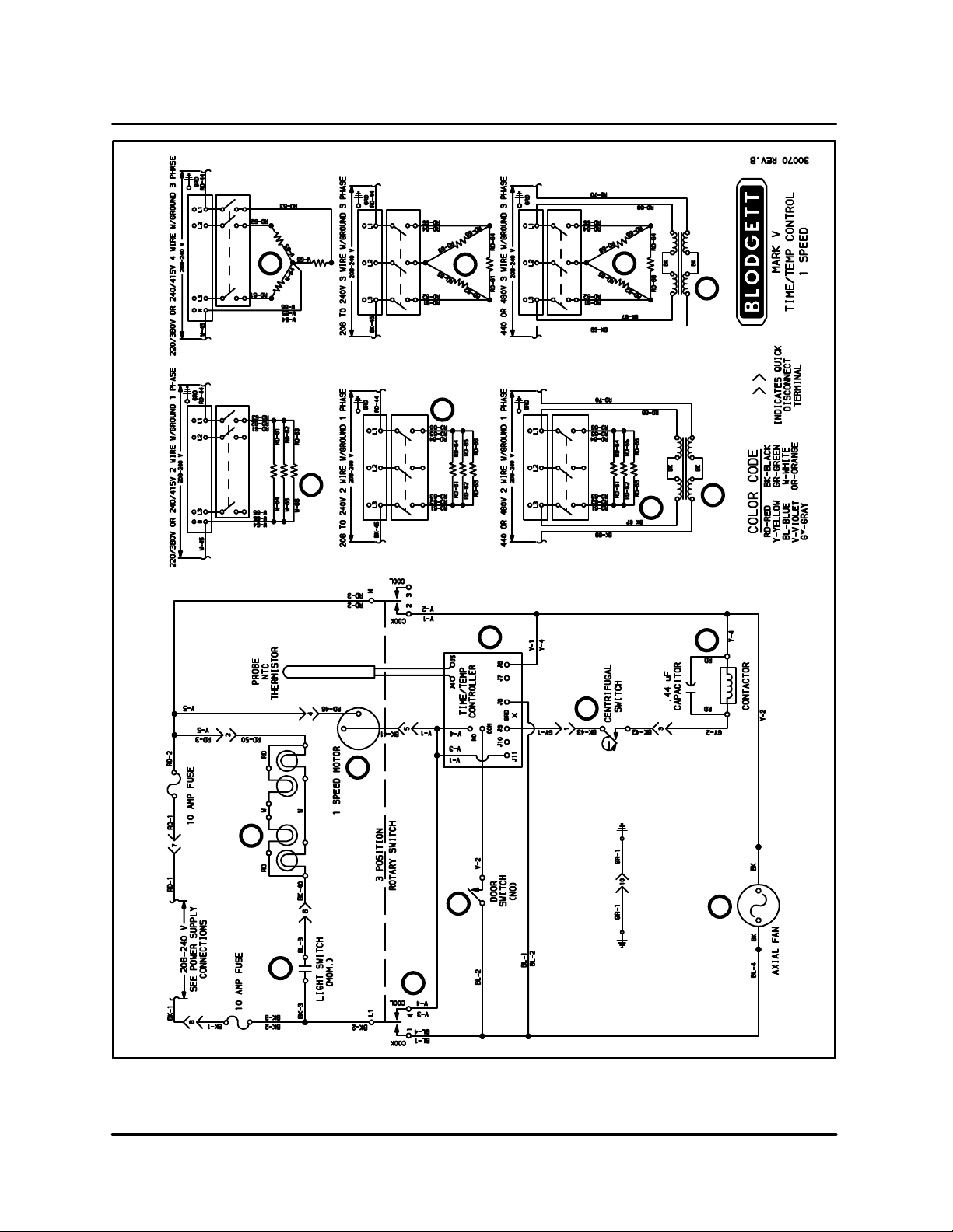
SOLID STATE DIGITAL - 30070 REV B
Component Reference
NOTE: Refer to FIGURE 4 page 2-9 for compoĆ
nent locations.
1. MODE SELECTOR SWITCH
2. DOOR SWITCH
3. TIME AND TEMPERATURE CONTROLLER
4. AXIAL FAN
5. CENTRIFUGAL SWITCH
6. CONVECTION FAN MOTOR
7. HOT AIR ELEMENT CONTACTOR
8. HEATING ELEMENTS
9. TRANSFORMER
10. 50 WATT LAMPS
11. LIGHT SWITCH
Operation
1. Turn the mode selector switch (1) to the cook
position. Power goes to one terminal of the
door switch (2), terminal J8 of the temperature
controller (3), and the axial fan (4). The main
blower fan starts. If a temperature is proĆ
grammed into the controller, the power goes
from J9 to the centrifugal switch (5) in the conĆ
vection fan motor (6).
2. If the doors are closed, the door switch (2)
should also be closed, sending power to the
common terminal of the time and temperature
controller (3). The relay on this controller
should be closed since a temperature has
been programmed into the controller. A circuit
is made between common and N.O. sending
power to, and starting the convection fan moĆ
tor (6).
NOTE: The relay in the time and temperature
controller is not field repairable. If
diagnosed as defective, the entire
board must be replaced.
3. When the convection fan motor (6) reaches full
speed the centrifugal switch (5) closes sendĆ
ing power to the coil of the hot air element conĆ
tactor (7). When the contactor closes power is
sent to the heating elements (8).
4. The 50 watt lamps (10) only receive power when
the light switch (11) is activated. These lamps
are 115 volt and are wired in series parallel.
NOTE: Turn the mode selector switch to cool
down to bypass the door microswitch. This
allows the convection fan motor to operate
even when the doors are open.
NOTE: This oven may be converted from single to
three phase, however, contactors must be
changed due to the difference in amp
draw. Reference detail inset in FIGURE 4.
NOTE: The resistive values for the probes used in
this oven have descending temperature
coefficients. As the temperature increases
the resistive values decrease.
NOTE: Reference page 4-2 of the TroubleshootĆ
ing section for the reistive values of the
heating elements. The reading should be
taken in a cold state.
MARK V
2-9
1
11
2
3
4
5
6
7
10
8
8
8
8
8
8
9
9
FIGURE 4

OPERATION
2-10
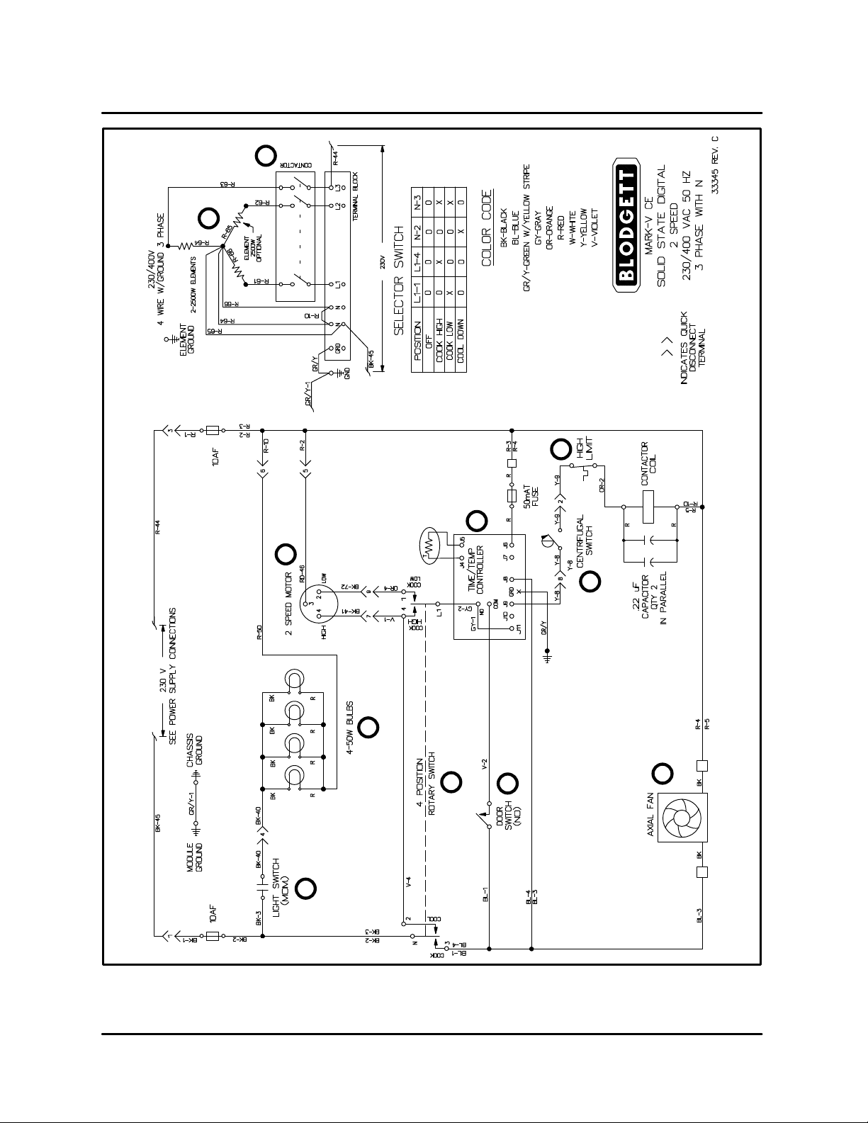
CE APPROVED SOLID STATE DIGITAL - 33345 REV C
Component Reference
NOTE: Refer to FIGURE 5 page 2-11 for compoĆ
nent locations.
1. MODE SELECTOR SWITCH
2. DOOR SWITCH
3. TIME AND TEMPERATURE CONTROLLER
4. AXIAL FAN
5. CENTRIFUGAL SWITCH
6. CONVECTION FAN MOTOR
7. HIGH LIMIT SWITCH
8. HOT AIR ELEMENT CONTACTOR
9. HEATING ELEMENTS
10. 50 WATT LAMPS
11. LIGHT SWITCH
Operation
1. Turn the mode selector switch (1) to the cook
position. Power goes to one terminal of the
door switch (2), terminal J8 of the temperature
controller (3), and the axial fan (4). The main
blower fan starts. If a temperature is proĆ
grammed into the controller, the power goes
from J9 to the centrifugal switch (5) in the conĆ
vection fan motor (6).
2. If the doors are closed, the door switch (2)
should also be closed, sending power to the
common terminal of the time and temperature
controller (3). The relay on this controller should
be closed since a temperature has been proĆ
grammed into the controller. A circuit is made
between common and N.O. sending power to,
and starting the convection fan motor (6).
NOTE: The relay in the time and temperature
controller is not field repairable. If
diagnosed as defective, the entire
board must be replaced.
3. When the convection fan motor (6) reaches full
speed the centrifugal switch (5) closes sending
power to the high limit (7). If the high limit is
closed, power goes to the coil of the hot air eleĆ
ment contactor (8). When the contactor closes
power is sent to the heating elements (9).
4. The 50 watt lamps (10) only receive power when
the light switch (11) is activated.
NOTE: Turn the mode selector switch to cool
down to bypass the door microswitch. This
allows the convection fan motor to operate
even when the doors are open.
NOTE: The resistive values for the probes used in
this oven have descending temperature
coefficients. As the temperature increases
the resistive values decrease.
MARK V
2-11
1
2
4
5
7
3
10
6
11
9
8
FIGURE 5

OPERATION
2-12
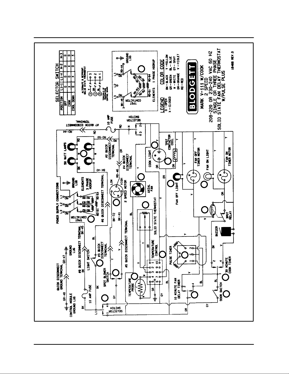
FAN DELAY WITH PULSE PLUS - 18466 REV D
Component Reference
NOTE: Refer to FIGURE 6 page 2-13 for compoĆ
nent locations.
1. MODE SELECTOR SWITCH
2. COOLING FAN
3. TEMPERATURE CONTROLLER
4. 10 MINUTE FAN DELAY TIMER
5. 30 MINUTE COOK TIMER
6. DOOR SWITCH
7. SPDT BLOWER SWITCH
8. CONVECTION FAN MOTOR
9. TEMPERATURE PROBE
10. POTENTIOMETER
11. HOT AIR ELEMENT CONTACTOR
12. COOK LIGHT
13. HOT AIR ELEMENTS
14. REPEAT SHOT PULSE TIMER
15. TPDT RELAY
16. FAN ON LIGHT
17. FAN OFF LIGHT
18. 50 WATT LAMPS
19. LIGHT SWITCH
Operation
1. Turn the mode selector switch (1) to the cook
position. Power goes to the cooling fan (2), terĆ
minal #8 of the temperature controller (3), and
terminal #1 of the ten minute fan delay timer (4).
2. If the ten minute fan delay timer is in the timed
out position a switch is made between terminals
#1 and #4 sending power to terminal #1 of the
thirty minute cook timer (5). Power is also sent
to one side of the door switch (6). If the doors are
closed the door switch should also be closed
sending power to terminal #6 of the temperature
control board (3) and the common terminal of a
SPDT blower switch (7). The speed of the conĆ
vection fan motor (8) is dependant on the posiĆ
tion of the SPDT blower switch.
3. On a call for heat from the cook temperature
control system a circuit is completed between
terminals #6 and #7 of the temperature conĆ
trol board (3).
NOTE: The temperature control system conĆ
sists of the temperature probe (9), the
temperature control board (3) and the
solid state potentiometer (10)
Power is sent out of terminal #7 to one coil of
the hot air element contactor (11) and the cook
light (12). When the contactor is energized the
hot air element (13) powers up.
4. To enable the pulse plus feature, the ten minĆ
ute fan delay timer (4) must be set to a time. A
switch is then made between terminals #1 and
#2 sending power to terminal #2 of a repeat
shot pulse timer (14).
NOTE: By setting the ten minute fan delay timer
(4) power is interrupted to the thirty minĆ
ute cook timer (5) making it inoperative.
The repeat shot pulse timer cycles a TPDT relay
(15) interrupting the circuit to the convection fan
motor (8). The convection fan motor cycles on
and off for approximately thirty second intervals
for the duration of the time set on the ten minute
fan delay timer (4). The fan on light (16) illumiĆ
nates whenever the TPDT relay closes. The fan
off light (17) illuminates whenever the ten minute
fan delay timer is set for a time.
5. The 50 watt lamps (18) only receive power when
the light switch (19) is activated. These lamps
are 115 volt and are wired in series parallel.
NOTE: Turn the mode selector switch to cool
down to bypass the door microswitch. This
allows the convection fan motor to operate
even when the doors are open.
NOTE: This oven may be converted from single to
three phase, however, contactors must be
changed due to the difference in amp
draw. Reference detail inset in FIGURE 6.
NOTE: The resistive values for the probes used in
this oven have descending temperature
coefficients. As the temperature increases
the resistive values decrease.
MARK V
2-13
1
19
7
9
3
14
4
6
5
15
16
17
11
12
10
2
8
13
18
13
FIGURE 6
 Loading...