


Mark V
electric convection oven INSTALLATION OPERATION MAINTENANCE
BLODGETT OVEN COMPANY
www.blodgett.com
44 Lakeside Avenue, Burlington, Vermont 05401 USA Telephone: (802) 658-6600 Fax: (802)864-0183
PN 33101 Rev K (3/14)
© 2014 G.S. Blodgett Corporation

Your Service Agency’s Address:
Model
Serial number
Oven installed by
Installation checked by

IMPORTANT
WARNING: Improper installation, adjustment, alternation, service or maintenance can cause property damage, injury or death. Read the instllation, operation and maintenance instructions thoroughly before installing or servicing this equipment.
FOR YOUR SAFETY
Do not store or use gasoline or other flammable vapors or liquids in the vicinity of this or any other appliance.
The information contained in this manual is important for the proper installation, use, and maintenance of this oven. Adherence to these procedures and instructions will result in satisfactory baking results and long, trouble free service. Please read this manual carefully and retain it for future reference.
ERRORS: Descriptive, typographic or pictorial errors are subject to correction. Specifications are subject to change without notice.
TABLE OF CONTENTS
INSTALLATION
Oven Description and Specifications.. . . . . . . . . . . . . . . . . . . . . . . . . . . . . . . . . . . . . . . 2
Delivery and Location. . . . . . . . . . . . . . . . . . . . . . . . . . . . . . . . . . . . . . . . . . . . . . . . . . . . . 3
Utility Connections Standards and Codes.. . . . . . . . . . . . . . . . . . . . . . . . . . . . . . . . . . 4
Electrical Connection.. . . . . . . . . . . . . . . . . . . . . . . . . . . . . . . . . . . . . . . . . . . . . . . . . . . . . 5
Oven Assembly and Startup. . . . . . . . . . . . . . . . . . . . . . . . . . . . . . . . . . . . . . . . . . . . . . . 6
OPERATION
IQ VVC-208 Control.. . . . . . . . . . . . . . . . . . . . . . . . . . . . . . . . . . . . . . . . . . . . . . . . . . . . . . 8 Component Description.. . . . . . . . . . . . . . . . . . . . . . . . . . . . . . . . . . . . . . . . . . . . . . . 8 Operational Test Procedure.. . . . . . . . . . . . . . . . . . . . . . . . . . . . . . . . . . . . . . . . . . . 9 Recipe Review.. . . . . . . . . . . . . . . . . . . . . . . . . . . . . . . . . . . . . . . . . . . . . . . . . . . . . . . 9 View Temperature Setting.. . . . . . . . . . . . . . . . . . . . . . . . . . . . . . . . . . . . . . . . . . . . . 9 Cool Down. . . . . . . . . . . . . . . . . . . . . . . . . . . . . . . . . . . . . . . . . . . . . . . . . . . . . . . . . . . 9 Setback.. . . . . . . . . . . . . . . . . . . . . . . . . . . . . . . . . . . . . . . . . . . . . . . . . . . . . . . . . . . . 10 Programming.. . . . . . . . . . . . . . . . . . . . . . . . . . . . . . . . . . . . . . . . . . . . . . . . . . . . . . . 10 Changing the Menu Strip. . . . . . . . . . . . . . . . . . . . . . . . . . . . . . . . . . . . . . . . . . . . . 10 Recipe Programming (1724). . . . . . . . . . . . . . . . . . . . . . . . . . . . . . . . . . . . . . . . . . 11 System Programming (6647).. . . . . . . . . . . . . . . . . . . . . . . . . . . . . . . . . . . . . . . . . 16 Product or Alarm Name Library (6647). . . . . . . . . . . . . . . . . . . . . . . . . . . . . . . . . 19 SCK Address (6647). . . . . . . . . . . . . . . . . . . . . . . . . . . . . . . . . . . . . . . . . . . . . . . . . 21
Blodgett IQ™ Phase IV Control. . . . . . . . . . . . . . . . . . . . . . . . . . . . . . . . . . . . . . . . . . . 22 Component Description.. . . . . . . . . . . . . . . . . . . . . . . . . . . . . . . . . . . . . . . . . . . . . . 22 Oven Operation Startup:.. . . . . . . . . . . . . . . . . . . . . . . . . . . . . . . . . . . . . . . . . . . . . 23 Programming Single Stage Recipes. . . . . . . . . . . . . . . . . . . . . . . . . . . . . . . . . . . 25 Programming Multiple Stage Recipes.. . . . . . . . . . . . . . . . . . . . . . . . . . . . . . . . . 27 2ND Level Programming.. . . . . . . . . . . . . . . . . . . . . . . . . . . . . . . . . . . . . . . . . . . . . 30 Programming the Offset. . . . . . . . . . . . . . . . . . . . . . . . . . . . . . . . . . . . . . . . . . . . . . 31 Replacing the Recipe Card.. . . . . . . . . . . . . . . . . . . . . . . . . . . . . . . . . . . . . . . . . . . 31
MAINTENANCE
Cleaning and Preventative Maintenance. . . . . . . . . . . . . . . . . . . . . . . . . . . . . . . . . . . 32

 Installation
Oven Description and Specifications
Cooking in a convection oven differs from cooking in a conventional deck or range oven since heated air is constantly recirculated over the product by a fan in an enclosed chamber. The moving air continually strips away the layer of cool air surrounding the product, quickly allowing the heat to penetrate. The result is a high quality product, cooked at a lower temperature in a shorter amount of time.
Blodgett convection ovens represent the latest advancement in energy efficiency, reliability, and ease of operation. Heat normally lost, is recirculated within the cooking chamber before being vented from the oven: resulting in substantial reductions in energy consumption and enhanced oven performance.
electrical ratings per section
voltage |
hz |
|
kW |
Phase |
|
max load (amps) |
|
Motor |
|||
|
|
|
|
|
|
|
|||||
|
L1 |
|
L2 |
L3 |
|
N |
|||||
|
|
|
|
|
|
|
|
||||
U.S. and Canadian installations |
|
|
|
|
|
|
|
|
|
||
208 |
60 |
|
11.0 |
1 |
51 |
|
— |
51 |
|
— |
6 AWG |
208 |
60 |
|
11.0 |
3 |
31 |
|
29 |
29 |
|
— |
8 AWG |
220-240 |
60 |
|
11.0 |
1 |
44 |
|
— |
44 |
|
— |
6 AWG |
220-240 |
60 |
|
11.0 |
3 |
26 |
|
24 |
24 |
|
— |
8 AWG |
440 |
60 |
|
11.0 |
3 |
15 |
|
14 |
14 |
|
— |
12 AWG |
480 |
60 |
|
11.0 |
3 |
14 |
|
13 |
13 |
|
— |
12 AWG |
General Export installations |
|
|
|
|
|
|
|
|
|
||
208 |
50 |
|
11.0 |
3 |
18 |
|
18 |
18 |
|
4 |
Size per local code |
220-240 |
50 |
|
11.0 |
1 |
48 |
|
— |
— |
|
48 |
Size per local code |
220/380 |
50 |
|
11.0 |
3 |
18 |
|
16 |
16 |
|
2 |
Size per local code |
240/415 |
50 |
|
11.0 |
3 |
18 |
|
14 |
14 |
|
4 |
Size per local code |
230/400 |
50 |
|
11.0 |
3 |
18 |
|
15 |
15 |
|
3 |
Size per local code |
NOTE: Electrical connection wiring is sized for 90°C copper wire at 125% of rated input.
2

Installation 
DELIVERY AND INSPECTION
All Blodgett ovens are shipped in containers to prevent damage. Upon delivery of your new oven:
•Inspect the shipping container for external damage. Any evidence of damage should be noted on the delivery receipt which must be signed by the driver.
•Uncrate the oven and check for internal damage. Carriers will accept claims for concealed damage if notified within fifteen days of delivery and the shipping container is retained for inspection.
The Blodgett Oven Company cannot assume responsibility for loss or damage suffered in transit. The carrier assumed full responsibility for delivery in good order when the shipment was accepted. We are, however, prepared to assist you if filing a claim is necessary.
OVEN LOCATION
The well planned and proper placement of your oven will result in long term operator convenience and satisfactory performance.
The following clearances must be maintained between the oven and any combustible or non-combustible construction.
•Oven body right side 1/2” (1.3cm)
•Oven body left side 1/2” (1.3cm)
•Oven body back 1/2” (1.3cm)
•Oven body bottom 1/2” (1.3cm)
The following clearances must be available for servicing.
•Oven body sides 12” (30cm)
•Oven body back 12” (30cm)
Delivery and Location
It is essential that an adequate air supply to the oven be maintained to provide a sufficient flow of combustion and ventilation air.
•Place the oven in an area that is free of drafts.
•Keep the oven area free and clear of all combustibles such as paper, cardboard, and flammable liquids and solvents.
•Do not place the oven on a curb base or seal to a wall. This will restrict the flow of air and prevent proper ventilation. Tripping of the blower motor’s
thermal overload device is caused by an excessive ambient temperature at the back of the oven. This condition must be corrected to prevent permanent damage to the oven.
•The location must provide adequate clearance for the air opening into the combustion chamber.
Before making any utility connections to this oven, check the rating plate to be sure the oven specifications are compatible with the gas and electrical services supplied for the oven.
1.Pull out control panel. The rating plate attached to the inside of the control compartment.
3

 Installation
Utility Connections Standards and Codes
THE INSTALLATION INSTRUCTIONS CONTAINED HEREIN ARE FOR THE USE OF QUALIFIED INSTALLATION AND SERVICE PERSONNEL ONLY. INSTALLATION OR SERVICE BY OTHER THAN QUALIFIED PERSONNEL MAY RESULT IN DAMAGE TO THE OVEN AND/OR INJURY TO THE OPERATOR.
Qualified installation personnel are individuals, a firm, a corporation, or a company which either in person or through a representative are engaged in, and responsible for:
•the installation of electrical wiring from the electric meter, main control box or service outlet to the electric appliance.
Qualified installation personnel must be experienced in such work, familiar with all precautions required, and have complied with all requirements of state or local authorities having jurisdiction.
U.S. and Canadian installations
All ovens, when installed, must be electrically grounded in accordance with local codes, or in the absence of local codes, with the National Electrical code, ANSI/NFPA 7o-Latest Edition and/or canadian National Electric code c22.2 as applicable.
The ventilation of this oven should be in accordance with local codes. In the absence of local codes, refer to the National ventilation code titled, “Standard for the Installation of Equipment for the Removal of Smoke and Grease Laden Vapors from commercial cooking Equipment”, NF- PA-96-Latest Edition.
General export installations
Installation must conform with Local and National installation standards. Local installation codes and/or requirements may vary. If you have any questions regarding the proper installation and/or operation of your Blodgett oven, please contact your local distributor. If you do not have a local distributor, please call the Blodgett Oven Company at 0011-802-860-3700.
4

Installation 
Ovens are supplied for operation on several different voltages with single or three phase grounded circuits. The electric motor (single or two speed), heating elements, oven lights, indicator lights and related switches are connected by one power supply to the oven. Before making any electrical connections to this unit, check the oven rating plate located on the underside of the upper ledge above the right hand door. Be sure the proper electrical supply is connected to the oven.
All ovens, when installed, must be electrically grounded in accordance with local codes or in the absence of local codes, with the National Electrical Code, ANSI/NFPA 70-Latest Edition and/or Canadian Electrical Code CSA C22.1 as applicable.
Wiring diagrams are located on the control compartment cover and at the back of the oven.
WARNING!!
In order to prevent damage, there is no power to the heating elements unless the blower is operating.
U.S. and Canadian Installations
For Single Phase Installations:
1.Connect the supply conduit to the wire duct located in the lower left hand corner as viewed from the rear of the oven.
2.Run the supply wires through the wire duct to the front of the oven. Connect the wires to the terminal block located at the lower right front corner.
NOTE: Remove the bottom trim and control compartment covers to access the terminal block. Slide the control module forward for easy connections.
For Three Phase Installations:
These units are supplied with a power cord and a 15-50P NEMA plug (4 prong grounding 50 amp 250 volt). It is intended for use with a 15-50R NEMA receptacle.
Export Installations
Export ovens are not supplied with a power cord. Size the electrical connection in accordance with local and National installation standards.
Electrical Connection
Terminal Block |
Single Phase Installations |
Three Phase Installations |
Figure 1
5
 Installation
Oven Assembly and Startup
Check that all of the components for your oven configuration were received. In addition to the oven itself, legs or other accessories may be required.
NOTE: In MARK V series ovens the legs are packed in the oven.
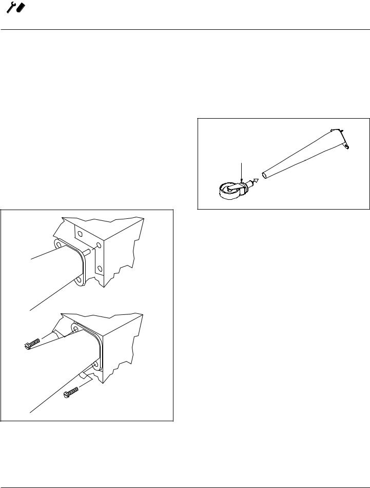
LEG AND CASTERS
1.With the oven lying on it’s back, align the threaded stud in each leg with the nut located inside each bottom front corner of the oven frame. Turn the legs clockwise and tighten to the nearest full turn.
2.Align the two leg plate holes in each leg with those in the oven bottom and secure the leg using two 1/2” bolts.
NOTE: For bolts on front and back edge of oven, hand tighten only. They will need to be removed for shelf installation.
Figure 2
3.Slide the caster assemblies into the bottom of each leg. Hand tighten the two set screws on the side of each caster.
NOTE: Two casters with locking devices must be installed on the front of the oven. casters without locking devices must be installed at the rear of the oven.
Adjustment Collar
Figure 3
4.Carefully tip the oven up on the newly installed legs and casters.
5.Place a level on top of the oven. Loosen the set screws on the side of each caster. Turn the adjustment collar clockwise to raise and counter clockwise to lower the oven.
6.When the oven is level, tighten the casters by turning the two set screws on the side of each caster assembly.
NOTE: When casters are used in conjunction with a power supply cord for movable appliances, a fixed restraint should be provided.
This restraint should secure the oven to a non-movable surface to eliminate stress on the connector. If the oven is moved from its regular location, the restraint must be reconnected when the oven is returned.
6
Installation 
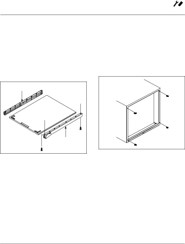
SHELF INSTALLATION
1.Remove the 4 leg mounting bolts from the front and back edge of the oven.
2.Line the front and back holes of the right channel assembly with the leg mounting bolt holes on the right side of the oven.
3.Secure using the leg mounting bolts.
4.Repeat steps 2-3 for the left channel assembly.
5.Slide the shelf into the track in the channel assemblies.
Left Channel |
Assembly |
Back of |
Oven |
Shelf Assembly |
Front of |
Oven |
Right Channel |
Assembly |
Figure 4
Oven Assembly and Startup
NSF BOLTS
These bolts are required by NSF to block any exposed hole on the back of an oven. This includes:
•any unit, single or stacked, without a back panel.
•any holes in stacked units not used for mounting stacking brackets.
1.Locate the 5/16” bolts that were shipped with the oven.
2.Install the bolts as shown.
Units without back panels
Figure 5
INITIAL STARTUP
Each oven, and its component parts, have been thoroughly tested and inspected prior to shipment. However, it is often necessary to further test or adjust the oven as part of a normal and proper installation. These adjustments are the responsibility of the installer, or dealer. Because these adjustments are not considered defects in material or workmanship, they are not covered by the Original
Equipment Warranty. They include, but are not limited to: calibration of the thermostat, adjustment of the doors, leveling, and tightening of fasteners. No installation should be considered complete without proper inspection, and if necessary, adjustment by qualified installation or service personnel.
7
 Operation
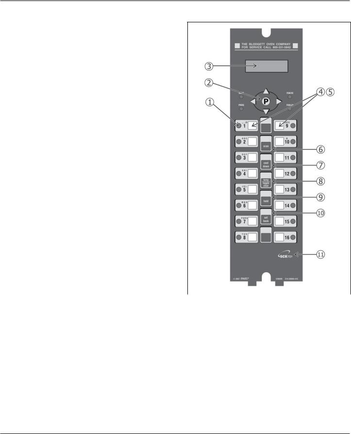
IQ VVC-208 Control
Component Description
1. |
Indicator |
Light up when product key is |
|
|
|
|
Lights |
activated |
|
|
|
|
|
|
|
|
|
2. |
Programming |
Used to access programming |
|
|
|
|
Buttons |
mode and change parameters |
|
|
|
|
|
|
|
|
|
3. |
VFD (Vacu- |
Bright blue for easy viewing. |
|
|
|
|
um Fluores- |
Displays programming and cook |
|
|
|
|
cent Display) |
cycle information |
|
|
|
|
|
|
|
|
|
4. |
Slide-In |
Menu items are printed directly |
|
|
|
|
Menu Strips |
on easy-to-change menu strip |
|
|
|
|
|
|
|
|
|
5. |
Product |
Used to activate cook cycles |
|
|
|
|
Buttons |
and for certain programming |
|
|
|
|
|
functions |
|
|
|
|
|
|
|
|
|
6. |
SCAN key |
Used for recipe review during |
|
|
|
|
|
idle. |
|
|
|
|
|
Used to review time remaining |
|
|
|
|
|
during multiple cooks (press & |
|
|
|
|
|
hold) |
|
|
|
|
|
|
|
|
|
7. |
COOL |
Used to enter or exit cool down |
|
|
|
|
DOWN key |
mode |
|
|
|
|
|
|
|
|
|
8. |
TEMP/ |
Used to check actual tempera- |
|
|
|
|
TOGGLE |
ture; also used to clear value |
|
|
|
|
CLEAR key |
when in programming mode |
|
|
|
|
|
|
|
|
|
9. |
HOLD key |
Holds are not used for RFC |
|
|
|
|
|
applications. Used to toggle |
|
|
|
|
|
between upper and lower case |
|
|
|
|
|
letters when programming |
|
|
|
|
|
libraries |
|
|
|
|
|
|
Figure 6 |
||
|
|
|
|
||
10. |
SETBACK |
Used to enter or exit Setback |
|||
|
|
||||
|
key |
mode |
|
|
|
|
|
|
|
|
|
11. |
SCK LINK |
Signifies your control is commu- |
|
|
|
|
logo |
nications capable |
|
|
|
|
|
|
|
|
8
Operation 
IQ VVC-208 Control
Operational Test Procedure
1 |
Plug oven into electrical source |
|
|
2 |
Turn the oven power switch on. |
|
NOTE: AP and Mark V computer is unpowered if off. |
|
|
3 |
NOTE: This scrolling can be bypassed by pressing ScAN. |
|
The controller will scroll through the following: |
|
a.) Appliance Type |
|
b.) Software # |
|
c.) Download # |
|
d.) SCK Address |
|
e.) “PREHEAT” |
|
|
4 |
The oven will enter “PREHEAT” mode and begin to warm up. When the set temperature (default 325°F) is |
|
reached, the Preheat timer will count down from 45 minutes to zero. When “LOAD” is displayed, the oven |
|
is ready for use. |
|
|
5 |
Press any illuminated product key. |
|
|
6 |
The cook cycle will count down in the display. |
|
|
Recipe Review
Quickly see what is programmed for each product key.
1.Press the SCAN key.
2.Select any product key previously programmed-LED will be lit above the key.
3.Press the DOWN arrow key to scroll through the list.
4.Press SCAN to exit.
View Temperature Setting
1.Press the TEMP key ‘once’ to view Actual Temperature, or
2.Press the TEMP key ‘twice’ to view Set Temperature.
3.Press the TEMP key ‘three’ times to view Fan Speed
4.Press the TEMP key ‘four’ times to view Fan Direction
Cool Down
1.To enter Cool Down, press the COOL DOWN key while the oven door is closed. When the display reads “COOL,” the door can then be opened.
WARNING!!
THE FAN IS STILL MOVING. DO NOT REACH INTO THE OVEN. The fan will automatically shut off when the actual temperature reaches 105°F.
2.To exit Cool Down, press the COOL DOWN key again. The oven will come back up to set temperature.
WARNING!!
ALWAYS TURN OFF MAIN POWER BEFORE REMOVING BAFFLE OR PLACING HANDS NEAR FAN.
9

 Operation
IQ VVC-208 Control
Setback
1.Used to manually reduce the set temperature temporarily during times of infrequent cooking. Press the
SETBACK key once to reduce the set temperature to the pre-programmed setback temperature.
2.Press the SETBACK key again to exit Setback and warm back up to the operating temperature.
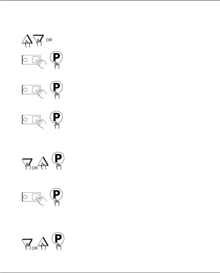
Programming
1.Programming Mode for the Vision Controller is entered by pressing the “P” key for three (3) seconds. The following programming mode is available on the VVC-208 as follows:
Access Level |
Passcode |
||
|
|
|
|
Employees |
|
1724 |
|
|
|
|
|
Managers |
|
6647 |
|
|
|
|
|
|
|
|
|
Program Area |
Employee |
|
Manager |
|
|
|
|
System |
n/a |
|
X |
|
|
|
|
Recipe |
X |
|
n/a |
|
|
|
|
Product Name |
X |
|
X |
Library |
|
|
|
|
|
|
|
Alarm Library |
X |
|
X |
|
|
|
|
SCK Address |
X |
|
X |
|
|
|
|
NOTE: Pressing the “P” key saves the previous parameter.
NOTE: If no key is pressed within 2 minutes while in Programming mode, the controller will automatically return to idle mode.
NOTE: All scrolling will loop back through allowed values.
Changing the Menu Strip
1 |
Turn off the oven power. |
|
|
2 |
With a Phillips screwdriver, remove the two |
|
screws that secure the bezel of the VVC-208 in |
|
place. Remove the bezel. |
|
|
3 |
Remove the existing menu strip(s) by lifting the |
|
tab and pulling the menu strip out from the bot- |
|
tom of the controller. |
|
|
4 |
Using the tab as a guide, slide the new menu |
|
strip in. |
|
|
5 |
Replace the bezel and screws that secure it to |
|
the controller. |
|
|
6 |
Turn on the oven power. |
|
|
10
|
|
|
Operation |
|
|
|
|
IQ VVC-208 Control |
|
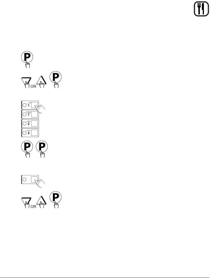
Recipe Programming (1724) |
|
|
|
|
|
|
|
|
|
|
KEY PRESS |
DISPLAY |
ACTION |
|
1 |
Enter Program mode |
|
• To enter programming mode, |
|
|
|
|
press and hold the “P” key for |
|
|
|
|
3 seconds. |
|
|
|
|
• Scroll down to “Programming” |
|
|
|
|
• Press the “P” key to lock in |
|
|
|
|
entry |
|
|
|
|
• The display will prompt user |
|
|
|
|
to enter a pass code |
|
|
|
|
|
|
2 |
Enter Pass Code |
ENTER CODE |
• Enter pass code 1 7 2 4 |
|
|
|
|
• Press the “P” key to lock in |
|
|
|
**** RECIPE |
your entry |
|
|
|
|
• Display will show “Recipe.” |
|
|
|
|
Press the “P” key |
|
|
|
|
|
|
3 |
Choose a Product Key (Recipe) |
SELECT PRODUCT TO |
• Press the product key to be |
|
|
|
PROGRAM |
programmed. That key’s LED |
|
|
|
|
will remain lit |
|
|
|
Choices are: ALL, NAME, TIME, |
• Scroll to the feature you want |
|
|
|
TEMPERATURE, TIMING, |
changed and press the “P” |
|
|
|
SENSITIVITY, FAN SPEED FAN |
key |
|
|
|
CYCLE, FAN PULSE ON, FAN |
NOTE: Selecting |
“ALL” al- |
|
|
PULSE OFF, ALARM TIME, |
||
|
|
lows you |
to review |
|
|
|
ALARM NAME, ALARM DONE, |
||
|
|
and/or change all pa- |
||
|
|
ALARM TONE, HOLD TIME, |
||
|
|
rameters for that key. |
||
|
|
HOLD TEMP, HOLD DONE, |
||
|
|
• To jump to a specific feature, |
||
|
|
HOLD FAN SPEED, |
||
|
|
PRODUCTS HEADS, EXIT |
select one from the list and |
|
|
|
|
follow the appropriate instruc- |
|
|
|
|
tions to make the changes |
|
|
|
|
|
|
11
 Operation
IQ VVC-208 Control
RECIPE PROGRAMMING (1724)
|
KEY PRESS |
DISPLAY |
ACTION |
4 |
Choose a Product Name |
PRODUCT NAME |
• Press the UP or DOWN arrow |
|
|
|
keys to scroll through prod- |
|
|
|
uct names, OR start spelling |
|
|
|
the desired product name by |
|
|
|
using the top row of lettered |
|
|
|
product keys |
|
|
|
• Press the “P” key to lock in |
|
|
|
selection |
|
|
|
|
5 |
Set Stage 1 Cook Time |
STAGE 1 TIME |
• Type in the time for Stage 1 |
|
|
MM:SS |
• Range is from 00:00 to 99:59 |
|
|
|
|
|
|
|
• Press the “P” key to advance |
|
|
|
to next stage or parameter |
|
|
|
|
6 |
Set Stage 1 Temperature |
STAGE 1 TEMP |
• Type in the Setpoint tem- |
|
|
XXX F |
perature for this stage. Range |
|
|
is from 140 to 500F, or the |
|
|
|
|
|
|
|
|
equivalent of Degrees C |
|
|
|
• Press the “P” key to advance |
|
|
|
to the next stage or param- |
|
|
|
eter |
|
|
|
|
7 |
Set Stage 1 Timing |
STAGE 1 TIMING |
• Press the LEFT or RIGHT |
|
|
(STRAIGHT, FLEX or |
arrow keys to select the type |
|
|
SENSITIVITY) |
of timing to be used for this |
|
|
|
stage |
|
|
|
• Press the “P” key to advance |
|
|
|
to next stage or parameter |
|
|
|
|
7A |
Set Sensitivity |
STAGE 1 SENS |
• THIS ONLY APPEARS IF |
|
|
(0 9) |
SENSITIVITY IS SELECTED |
|
|
ABOVE |
|
|
|
|
|
|
|
|
• Type in Sensitivity setting of |
|
|
|
0-9 |
|
|
|
• Press the “P” key to advance |
|
|
|
to next stage or parameter |
|
|
|
|
8 |
Set Stage 1 Fan Speed |
STAGE 1 FAN SPEED |
• Press the LEFT or RIGHT |
|
|
(HIGH, LOW) |
arrow keys to select the fan |
|
|
speed |
|
|
|
|
|
|
|
|
• Press the “P” key to advance |
|
|
|
to next stage or parameter |
|
|
|
|
12
 Loading...