


DFG 100 AND DFG 200 SERIES
CONVECTION OVEN
SERVICE AND REPAIR MANUAL
BLODGETT OVEN COMPANY
www.blodgett.com
44 Lakeside Avenue, Burlington, Vermont 05401 USA Telephone (802) 658)6600 Fax: (802)864)0183
PN 33082 Rev F (7/10)
E 2010 - G.S. Blodgett Corporation All rights reserved.
Duplication of the information in this manual is prohibited without the consent of the Blodgett Service Department.

|
|
TABLE OF CONTENTS |
|
|
|
|
|
1. |
INTRODUCTION |
|
|
|
Oven Specifications . . . . . . . . . . . . . . . . . . . . . . . . . . . . . . . . . . . . . . . . |
. . . . . . . . . . . . . . . . . . . . . . . 1-1 |
|
|
Ventilation . . . . . . . . . . . . . . . . . . . . . . . . . . . . . . . . . . . . . . . . . . . . . . . . . |
. . . . . . . . . . . . . . . . . . . . . . 1-3 |
|
2. |
OPERATION |
|
|
|
Manual Controls with Electro)Mechanical Thermostat . . . . . . . . . . . |
. . . . . . . . . . . . . . . . . . . . . . 2-1 |
|
|
Solid State Cook Only . . . . . . . . . . . . . . . . . . . . . . . . . . . . . . . . . . . . . . . |
. . . . . . . . . . . . . . . . . . . . . . 2-3 |
|
|
Solid State Cook & Hold . . . . . . . . . . . . . . . . . . . . . . . . . . . . . . . . . . . . . |
. . . . . . . . . . . . . . . . . . . . . . 2-5 |
|
|
Solid State Digital . . . . . . . . . . . . . . . . . . . . . . . . . . . . . . . . . . . . . . . . . . . |
. . . . . . . . . . . . . . . . . . . . . . 2-8 |
|
|
Fan Delay with Pulse Plus . . . . . . . . . . . . . . . . . . . . . . . . . . . . . . . . . . . |
. . . . . . . . . . . . . . . . . . . . . . 2-12 |
|
|
Humidaire . . . . . . . . . . . . . . . . . . . . . . . . . . . . . . . . . . . . . . . . . . . . . . . . . |
. . . . . . . . . . . . . . . . . . . . . . 2-15 |
|
|
Intelliplus with Chain Event Control . . . . . . . . . . . . . . . . . . . . . . . . . . . |
. . . . . . . . . . . . . . . . . . . . . . 2-18 |
|
|
Intellitouch . . . . . . . . . . . . . . . . . . . . . . . . . . . . . . . . . . . . . . . . . . . . . . . . . |
. . . . . . . . . . . . . . . . . . . . . . 2-20 |
|
|
Intellitouch II . . . . . . . . . . . . . . . . . . . . . . . . . . . . . . . . . . . . . . . . . . . . . . . |
. . . . . . . . . . . . . . . . . . . . . . 2-22 |
|
3. |
CALIBRATION AND ADJUSTMENT |
|
|
|
Doors . . . . . . . . . . . . . . . . . . . . . . . . . . . . . . . . . . . . . . . . . . . . . . . . . . . . . |
. . . . . . . . . . . . . . . . . . . . . . 3-1 |
|
|
Door Blower Switch . . . . . . . . . . . . . . . . . . . . . . . . . . . . . . . . . . . . . . . . . |
. . . . . . . . . . . . . . . . . . . . . . 3-2 |
|
|
Thermostat . . . . . . . . . . . . . . . . . . . . . . . . . . . . . . . . . . . . . . . . . . . . . . . . |
. . . . . . . . . . . . . . . . . . . . . . 3-2 |
|
|
Burners . . . . . . . . . . . . . . . . . . . . . . . . . . . . . . . . . . . . . . . . . . . . . . . . . . . |
. . . . . . . . . . . . . . . . . . . . . . 3-4 |
|
|
Solid State Manual . . . . . . . . . . . . . . . . . . . . . . . . . . . . . . . . . . . . . . . . . . |
. . . . . . . . . . . . . . . . . . . . . . 3-5 |
|
|
Intellitouch Control Second Level Programming . . . . . . . . . . . . . . . . |
. . . . . . . . . . . . . . . . . . . . . . 3-7 |
|
|
Solid State Digital Second Level Programming . . . . . . . . . . . . . . . . . |
. . . . . . . . . . . . . . . . . . . . . . 3-8 |
|
|
Intellitouch II Second Level Programming . . . . . . . . . . . . . . . . . . . . . . |
. . . . . . . . . . . . . . . . . . . . . . 3-9 |
|
|
Intelliplus Second Level Programming . . . . . . . . . . . . . . . . . . . . . . . . . |
. . . . . . . . . . . . . . . . . . . . . . 3-10 |
|
4. |
PARTS REPLACEMENT |
|
|
|
Access Panels and Doors . . . . . . . . . . . . . . . . . . . . . . . . . . . . . . . . . . . |
. . . . . . . . . . . . . . . . . . . . . . 4-1 |
|
|
Combustion Compartment Cover . . . . . . . . . . . . . . . . . . . . . . . . . |
. . . . . . . . . . . . . . . . . . . . . . 4-1 |
|
|
Control Cover . . . . . . . . . . . . . . . . . . . . . . . . . . . . . . . . . . . . . . . . . . |
. . . . . . . . . . . . . . . . . . . . . . 4-1 |
|
|
Perimeter Door Gasket . . . . . . . . . . . . . . . . . . . . . . . . . . . . . . . . . . |
. . . . . . . . . . . . . . . . . . . . . . 4-2 |
|
|
Center Door Gasket . . . . . . . . . . . . . . . . . . . . . . . . . . . . . . . . . . . . . |
. . . . . . . . . . . . . . . . . . . . . . 4-2 |
|
|
Oven Door . . . . . . . . . . . . . . . . . . . . . . . . . . . . . . . . . . . . . . . . . . . . . |
. . . . . . . . . . . . . . . . . . . . . . 4-3 |
|
|
Window Assembly for ovens with 50/50 Doors . . . . . . . . . . . . . . |
. . . . . . . . . . . . . . . . . . . . . . 4-3 |
|
|
Window Assembly for Ovens with 60/40 Doors . . . . . . . . . . . . . |
. . . . . . . . . . . . . . . . . . . . . . 4-3 |
|
|
Lower Door Hinge and Sprocket Assembly . . . . . . . . . . . . . . . . . |
. . . . . . . . . . . . . . . . . . . . . . 4-4 |
|
|
Door Chain Assembly . . . . . . . . . . . . . . . . . . . . . . . . . . . . . . . . . . . |
. . . . . . . . . . . . . . . . . . . . . . 4-4 |
|
|
Motor and Blower Assembly . . . . . . . . . . . . . . . . . . . . . . . . . . . . . . . . . |
. . . . . . . . . . . . . . . . . . . . . . 4-5 |
|
|
Blower Wheel . . . . . . . . . . . . . . . . . . . . . . . . . . . . . . . . . . . . . . . . . . . |
. . . . . . . . . . . . . . . . . . . . . . 4-5 |
|
|
Motor . . . . . . . . . . . . . . . . . . . . . . . . . . . . . . . . . . . . . . . . . . . . . . . . . . |
. . . . . . . . . . . . . . . . . . . . . . 4-5 |
|
|
Burner and Deflector Assemblies . . . . . . . . . . . . . . . . . . . . . . . . . . . . . |
. . . . . . . . . . . . . . . . . . . . . . 4-6 |
|
|
Manifold and Burner Orifices . . . . . . . . . . . . . . . . . . . . . . . . . . . . . |
. . . . . . . . . . . . . . . . . . . . . . 4-6 |
|
|
Burners . . . . . . . . . . . . . . . . . . . . . . . . . . . . . . . . . . . . . . . . . . . . . . . . |
. . . . . . . . . . . . . . . . . . . . . . 4-6 |
|
|
Compartment Liner Bottom . . . . . . . . . . . . . . . . . . . . . . . . . . . . . . . |
. . . . . . . . . . . . . . . . . . . . . . 4-6 |
|
i

TABLE OF CONTENTS
Deflector Assembly . . . . . . . . . . . . . . . . . . . . . . . . . . . . . . . . . . . . . . . . . . . . . . . . . . . . . . . . . . . . |
4-6 |
Electric Igniter (Glow Coil) and Plumbing Components . . . . . . . . . . . . . . . . . . . . . . . . . . . . . . . . |
4-7 |
Electric Igniter . . . . . . . . . . . . . . . . . . . . . . . . . . . . . . . . . . . . . . . . . . . . . . . . . . . . . . . . . . . . . . . . |
4-7 |
Thermal Delay Relay Assembly . . . . . . . . . . . . . . . . . . . . . . . . . . . . . . . . . . . . . . . . . . . . . . . . . |
4-7 |
Gas Pressure Regulator . . . . . . . . . . . . . . . . . . . . . . . . . . . . . . . . . . . . . . . . . . . . . . . . . . . . . . . . |
4-8 |
Solenoid Valve . . . . . . . . . . . . . . . . . . . . . . . . . . . . . . . . . . . . . . . . . . . . . . . . . . . . . . . . . . . . . . . . |
4-8 |
Control Stack Assembly . . . . . . . . . . . . . . . . . . . . . . . . . . . . . . . . . . . . . . . . . . . . . . . . . . . . . . . |
4-9 |
combination Dual Gas Valve . . . . . . . . . . . . . . . . . . . . . . . . . . . . . . . . . . . . . . . . . . . . . . . . . . . . |
4-9 |
Intermittent Ignition Device (IID) and Plumbing Components . . . . . . . . . . . . . . . . . . . . . . . . . . . |
4-10 |
Pilot Burner and Spark Ignition . . . . . . . . . . . . . . . . . . . . . . . . . . . . . . . . . . . . . . . . . . . . . . . . . |
4-10 |
Ignition Control and |
|
Transformer . . . . . . . . . . . . . . . . . . . . . . . . . . . . . . . . . . . . . . . . . . . . . . . . . . . . . . . . . . . . . . . . . . |
4-10 |
Control Stack Assembly . . . . . . . . . . . . . . . . . . . . . . . . . . . . . . . . . . . . . . . . . . . . . . . . . . . . . . . |
4-11 |
Combination Dual Gas Valve . . . . . . . . . . . . . . . . . . . . . . . . . . . . . . . . . . . . . . . . . . . . . . . . . . . |
4-11 |
Electrical Components . . . . . . . . . . . . . . . . . . . . . . . . . . . . . . . . . . . . . . . . . . . . . . . . . . . . . . . . . . . . |
4-12 |
Bulb and Capillary Thermostat . . . . . . . . . . . . . . . . . . . . . . . . . . . . . . . . . . . . . . . . . . . . . . . . . . |
4-12 |
Electrical Components Located in the Control Module . . . . . . . . . . . . . . . . . . . . . . . . . . . . . |
4-12 |
Door Switch . . . . . . . . . . . . . . . . . . . . . . . . . . . . . . . . . . . . . . . . . . . . . . . . . . . . . . . . . . . . . . . . . . |
4-12 |
5. TROUBLESHOOTING |
|
Heat HSI System . . . . . . . . . . . . . . . . . . . . . . . . . . . . . . . . . . . . . . . . . . . . . . . . . . . . . . . . . . . . . . . . . |
5-1 |
Flow Diagram . . . . . . . . . . . . . . . . . . . . . . . . . . . . . . . . . . . . . . . . . . . . . . . . . . . . . . . . . . . . . . . . . . . . |
5-3 |
Display Error Codes . . . . . . . . . . . . . . . . . . . . . . . . . . . . . . . . . . . . . . . . . . . . . . . . . . . . . . . . . . . . . . |
5-5 |
Probe resistance vs temperature . . . . . . . . . . . . . . . . . . . . . . . . . . . . . . . . . . . . . . . . . . . . . . . . . . . |
5-6 |
ii

CHAPTER 1
INTRODUCTION

DFG 100 and DFG 200
OVEN SPECIFICATIONS
VENTILATION REQUIREMENTS
Canopy Type Exhaust Hood
The preferred method of ventilation is the use of a mechanically driven, canopy type exhaust hood. The hood should completely cover the unit with an overhang of at least 6" (15 cm) on all sides not adja) cent to a wall. The distance from the floor to the low) er edge of the hood should not exceed 7' (2.1 m). The ventilation system should replace 80% of the exhaust volume with fresh make up air.
Direct Flue
NOTE: U.S. and Canadian installations only.
The minimum recommended clearance of the oven from any combustible, or non)combustible material should be 6" (15 cm). The height of the flue should rise 6)8' (2)2.5 m) above the roof of the building, or any proximate structure. The flue should be capped with a UL listed vent cap to isolate the unit from exter) nal environmental conditions.
The direct vent does not have the capability of re) placing air consumed and vented by the oven. It is important that provisions be made to supply the room with sufficient make)up air. Total make)up air requirements for each oven section should be about 19 CFM.
ELECTRICAL SPECIFICATIONS
NOTE: Three Phase hookup is not permitted on gas models.
WARNING: DO NOT INSTALL A •HIGH LEG" TO ANY CONVECTION OVEN!
The DFG)100 and DFG)200 ovens are supplied for connection to 115 VAC grounded circuits with the 6' (1.8 m) power cord supplied. All ovens, when installed must be electrically grounded in accor) dance with National Electric or local codes.
CE approved installations
Connect the oven to a separate group 230V, 50 hz with rigid connection and operating switch. Use 90_C wire and size according to local codes.
NOTE: The burner control unit is phase sensitive. If the phase and neutral are switched the control locks out.
Connect phase + neutral + ground.
|
L1 |
|
|
Supply |
N |
115 |
Oven |
|
|
||
|
U.S. Installations |
|
|
|
L1 |
|
|
Supply |
N |
230 |
Oven |
|
|
||
CE Approved Installations |
|||
FIGURE 1
1-1

INTRODUCTION
GAS SPECIFICATIONS
GAS CONNECTIONS
Domestic and General Export installations
The gas line should be large enough to accommo) date the peak demand of all the gas appliances. TABLE 1 reflects a straight line, 50 foot run with no coupling restrictions and no other appliances drawing service. Gas line installations MUST con) form to National Fuel Gas Code NFPA 54/ANSI Z223.1 Sec. 1.4 (Latest Edition). TABLE 1 should be used as a guideline only.
NOTE: For any pipe runs over 50 feet (15 m), con sult the factory.
CE approved installations
1.Connect the oven to the gas line with the prop) er type of gas according to Local and National Installation Standards. See TABLE 1.
GAS REQUIREMENTS
NOTE: For natural gas meter sizing, consult your local gas company to ensure that your me ter will provide the proper supply.
Installations within the U.S.
1.Add the total BTU's/hr of all the gas appliances.
2.Convert BTU's to cubic ft/hr using the formula Cu Ft/Hr = 1000 BTU/Hr for natural gas.
3.Size the meter accordingly.
Installations outside the U.S.
1.Add the total M3/min of all the appliances.
2.Size the meter accordingly.
DOMESTIC AND GENERAL EXPORT
|
|
Natural Gas |
Propane Gas |
||
|
|
|
|
|
|
|
US units |
SI units |
US units |
SI units |
|
|
|
|
|
|
|
Heating Value |
1000 |
BTU/hr |
37.3 MJ/m3 |
2550 BTU/hr |
95.0 MJ/m3 |
Specific Gravity (air = 1.0) |
0.63 |
0.63 |
1.53 |
1.53 |
|
|
|
|
|
|
|
Gas Manifold Pressure |
3.5" W.C. |
0.87 kPa |
10" W.C. |
2.49 kPa |
|
|
|
|
|
|
|
Oven Input |
|
|
|
|
|
DFG)100)3 |
55,000 BTU/hr |
16.2 kW/Hr. |
55,000 BTU/hr |
16.2 kW/Hr. |
|
DFG)200)L |
60,000 BTU/hr |
17.6 kW/Hr. |
60,000 BTU/hr |
17.6 kW/Hr. |
|
|
|
|
|
|
|
Main Burner Orifice Size |
|
|
|
|
|
DFG)100)3 |
40 |
MTD |
2.5 mm |
53 MTD |
1.5 mm |
DFG)200)L |
38 |
MTD |
2.6 mm |
1/16 dia. |
1.55 mm |
|
|
|
|
|
|
CE APPROVED UNITS
Type of |
Inlet |
Burner Pressure |
Injector |
Air |
Pilot |
Standard |
Gas |
Pressure |
mbars |
Diameter |
Opening |
Injector |
Delivery |
|
mbars |
|
mm |
mm |
mm |
Value kW (HS) |
G25 |
25 |
12 |
2,60 |
18 |
0,53 |
16,2 Nat. Gas |
|
|
|
|
|
|
|
G20 |
20 |
8 |
2,60 |
18 |
0,53 |
16,2 Nat. Gas |
|
|
|
|
|
|
|
G20/G25 |
20/25 |
Totally Inscrewed |
2,10 |
18 |
0,53 |
16,2 Nat. Gas |
|
|
Pressure Regulator |
|
|
|
|
|
|
|
|
|
|
|
G30 |
30/50 |
17 |
1,60 |
10 |
0,28 |
16,2 Butane |
|
|
|
|
|
|
|
G31 |
30/37/50 |
24 |
1,60 |
10 |
0,28 |
16,2 Propane |
TABLE 1
1-2

DFG 100 and DFG 200
VENTILATION
CANOPY TYPE EXHAUST HOOD
Ovens that are ordered for under)hood venting are supplied with a draft diverter. When supplied with a draft diverter, the oven must be installed under a mechanically driven exhaust hood.
1.To install, place the diverter with the open area toward the rear of the oven.
2.Secure both ends with the sheet metal screws provided.
Front of
Oven
FIGURE 2
DIRECT FLUE ARRANGEMENT
NOTE: Not available for CE approved installations.
Ovens that are ordered for direct venting are supplied with a direct vent.
1.To install, place the direct vent with the angle on the bottom facing toward the front of the oven
2.Secure both ends with the sheet metal screws provided.
Front of
Oven
FIGURE 3
TRIM COLLAR
1.Remove the trim collar from its shipping posi) tion at the rear of the oven.
2.Remove the protective coating from the stain) less steel portion of the collar.
3.Install the collar in the proper position at the top of the oven.
Trim Collar
Trim Collar
FIGURE 4
1-3

CHAPTER 2
OPERATION

DFG 100 and DFG 200
MANUAL CONTROLS WITH ELECTRO MECHANICAL THERMOSTAT
NOTE: The following instructions represent the most common controllers. For questions regarding other options call the Blodgett Service Department at (800)331 5842.
SEQUENCE OF OPERATION - DIAGRAM P/N 17794 REV A
Component Reference
NOTE: Refer to FIGURE 5 page 2-2 for compo nent locations.
1.MODE SELECTOR SWITCH
2.COOK THERMOSTAT
3.COOK TIMER
4.GAS SOLENOID
5.DOOR SWITCH
6.CONVECTION MOTOR
7.CENTRIFUGAL SWITCH
8.THERMAL DELAY RELAY
9.HOT SURFACE IGNITER
10.COOK LIGHT
11.BUZZER
12.LIGHT BULBS
13.LIGHT SWITCH
Operation
1.Power is applied to the appliance by a 110VAC power cord attached to the rear of the oven.
2.Power is at terminal L1 and N of the mode se) lector switch (1).
3.If the mode switch is turned on then a circuit is made between L1 and Terminal 1 allowing cur) rent flow to one side of the cook thermostat (2), cook timer (3), pilot valve portion of the gas so) lenoid valve (4) and one side of a SPST door switch (5).
4.If the door switch is closed, power goes to ter) minal #4 of the mode selector switch and to the L1 side of the convection motor (6) allowing the motor to start.
NOTE: The door switch is located behind the combustion cover and is operated by the cam that is mounted to the right hand hinge pin.
5.On a call for heat, the cook thermostat closes sending power to one side of a centrifugal switch (7). If the motor is operating at full speed, this switch should be closed sending power to terminals 8 and 6 of a thermal delay relay (8).
NOTE: The centrifugal switch is an integral part of the convection motor and is not field repairable.
NOTE: The thermostat is a fluid filled bulb and capillary style. The bulb is located in the upper right hand corner of the bake chamber.
6.The area connecting terminals 6 and 1 of the thermal delay relay is called a heater strip.
NOTE: The thermal delay relay contains both the heater strip and the set of contacts that operate the gas valve in what looks like an old TV tube. This tube is plugged into a socket, so removal of the tube is simple.
NOTE: This strip warms up as voltage is ap plied to the HSI.
7.As the hot surface igniter (9) gets hotter so does the heater strip. The heat from the strip causes two strips of metal to come together and touch allowing current to flow from termi) nal 8 to terminal 3 of the TDR to the main por) tion of the gas solenoid valve and an indicator light (10). This light goes on and off every time the main gas valve is powered up.
8.Gas flows to the burners and is ignited by the high temperature of the HSI.
9.The timer is a mechanical count down timer. It closes a set of contacts within the timer to pow) er up a buzzer (11) at the expiration of whatev) er time the operator dials in.
10.The lights (12) are operated by a STDP rocker switch (13).
2-1

|
OPERATION |
|
1 |
|
11 |
|
4 |
12 |
10 |
|
9 |
|
4 |
6 |
8b |
|
8a |
|
7 |
|
5 |
13 |
|
|
3 |
|
2 |
1 |
|
FIGURE 5
2-2
DFG 100 and DFG 200
SOLID STATE COOK ONLY
SEQUENCE OF OPERATION - DIAGRAM P/N 20027 REV A
Component Reference
NOTE: Refer to FIGURE 6 page 2-4 for compo nent locations.
1.MODE SWITCH
2.DOOR MICROSWITCH
3.TEMPERATURE CONTROL BOARD
4.AXIAL FAN
5.60 MINUTE TIMER
6.110/24 VOLT TRANSFORMER
7.TEMPERATURE PROBE
8.IGNITION CONTROL MODULE
9.TWO SPEED MOTOR
10.CENTRIFUGAL SWITCH
11.PILOT VALVE
12.PILOT BURNER
13.MAIN VALVE
14.LIGHT BULBS
15.LIGHT SWITCH
16.BUZZER
Operation
1.Power is applied to the appliance by a 110VAC power cord attached to the rear of the oven.
2.Power is at terminal L1 and N of the mode se) lector switch (1).
3.If the mode switch (1) is turned on a circuit is made between L1 and 1, N and 2 allowing cur) rent to flow to one side of a SPST door switch (2), terminal #8 of the solid state temperature control board (3), axial fan (4), terminal 1 of the cook timer (5) and to the primary side of a 110 volt to 24 volt transformer (6).
4.If the doors are closed, the door switch (2) should be closed sending power to the con) vection blower (9). When this motor reaches full speed a centrifugal switch (10) closes sending 24VAC to terminal 6 of the tempera)
ture control board (3) and the ignition control module (8).
NOTE: The door switch is located behind the combustion cover and is operated by the cam that is mounted on the right hand hinge pin.
NOTE: The centrifugal switch is an integral part of the convection blower and is not field repairable.
5.On a call for heat from the thermostat as sensed by an RTD probe (7), a set of contacts on the temperature control board (3) close completing a circuit to terminal 2 of the ignition control module (8).
NOTE: The thermostat consists of three com ponents (RTD probe, solid state tem perature control board and 1000 ohm potentiometer)
NOTE: The temperature probe has a de scending temperature coefficient.
6.After the ignition control module (8) completes a diagnostics and all functions check out, 24VAC is sent to the pilot valve (11) and a high energy spark jumps a gap at the pilot burner (12). Once the pilot is lit and the pilot flame is proven, the ignition control module (8) sends 24VAC to the main valve (13).
NOTE: A 24VAC indicator light is wired in par allel with the main valve to inform the operator that the main gas valve is be ing powered up. When the light goes out the thermostat is satisfied.
7.The lights (14) are controlled by a SPST rocker switch (15).
8.The buzzer (16) is controlled by a switch in the cook timer.
NOTE: The timer's only function is to count down and activate a buzzer. This will not shut down the oven.
2-3

|
|
OPERATION |
|
|
16 |
|
|
|
4 |
|
|
|
|
6 |
|
9 |
|
13 |
11 |
|
3 |
|
|
|
7 |
|
8 |
|
|
|
|
14 |
|
|
|
15 |
5 |
12 |
|
|
2 |
|
10 |
|
|
|
|
1 |
|
|
|
FIGURE 6
2-4

DFG 100 and DFG 200
SOLID STATE COOK & HOLD
SEQUENCE OF OPERATION - DIAGRAM P/N 19604 REV A
Component Reference
NOTE: Refer to FIGURE 7 page 2-7 for compo nent locations.
1.MODE SELECTOR SWITCH
2.DPDT RELAY
3.LIGHT SWITCH
4.60 MINUTE TIMER
5.110/24 VOLT TRANSFORMER
6.TEMPERATURE CONTROL BOARD
7.AXIAL FAN
8.HOLD TEMPERATURE CONTROL BOARD
9.DOOR MICROSWITCH
10.CONVECTION BLOWER MOTOR
11.CENTRIFUGAL SWITCH
12.IGNITION CONTROL MODULE
13.TPDT RELAY
14.COOK TEMPERATURE PROBE
15.A & B DUAL SOLENOID GAS VALVE
16.COOK & HOLD TIMER
17.HOLD INDICATOR LIGHT
18.HOLD TEMPERATURE PROBE
Operation
1.Power is applied to the appliance by a 110VAC power cord attached to the rear of the oven.
2.Power is at terminal L1 and N of the mode se) lector switch (1), one of the NC terminals of a DPDT relay (2) and one terminal of SPST light switch (3).
3.If the mode selector switch (1) is turned to the cook position a circuit is made between L1 and terminal 4. 110VAC flows to terminal 1 of the 60 minute timer (4), the primary side of a 110 to 24 volt transformer (5), terminals 6 and 8 of the temperature control board (6), axial cooling fan (7) and terminal 8 of the hold temperature board (8).
4.If the doors are closed, the door switch (9) should be closed sending power to the con) vection blower (10). This switch interrupts the neutral going to the motor. Once this motor reaches full speed a centrifugal switch (11) closes sending 24VAC to terminal 6 of the igni)
tion control module (12) and terminal 7 of a TPDT relay (13).
NOTE: The door switch is located behind the combustion cover and is operated by the cam mounted on the right hand hinge pin.
NOTE: The centrifugal switch is an integral part of the convection blower and is not field repairable.
5.On a call for heat from the thermostat as sensed by an RTD probe (14), a set of contacts on the temperature control board (6) closes completing a circuit between terminals 6 and 7 allowing 110 volts AC to go to one of the nor) mally closed contacts on the DPDT relay (2). The relay sends 110 volts AC to the coil of the TPDT relay (13) allowing the circuit to be made between terminals 7 and 4 of the same relay. This completes the circuit to the ignition con) trol module (12).
NOTE: The thermostat consists of three com ponents (RTD probe, solid state tem perature control board and a 1000 ohm potentiometer.)
NOTE: The temperature probe has a de scending temperature coefficient.
6.After the ignition control module (12) has com) pleted a diagnostics and all functions check out, 24VAC is sent to the pilot valve (15a) and a high energy spark jumps a gap at the pilot burner. Once the pilot is lit and the pilot flame is proven, the ignition control (12) sends 24VAC to the main valve (15b).
NOTE: A 24VAC indicator light is wired in par allel with the main valve to inform the operator that the main gas valve is be ing powered up. When the light goes out the thermostat is satisfied.
2-5

OPERATION
7.If the mode selector switch (1) is set to the Cook & Hold position a circuit is made in the switch between L1, 1 and 4. All of the previous) ly mentioned circuitry is active as well as the cook and hold circuit.
8.At the expiration of time on the cook and hold timer (16) a circuit is made between terminals 1 and 4 allowing power to go to a hold indicator light (17), terminal 6 of the hold temperature board and the coil of the DPDT relay (2) allow) ing the relay (8) to toggle between C-NC to C-NO terminals.
9.When there is a demand for heat from the hold temperature board (8) as sensed by the tem) perature probe (18) a set of contacts on the temperature control board closes completing a circuit between terminals 6 and 7 allowing 110VAC to go to one of the normally open con) tacts on the DPDT relay (2) which in turns sends 110VAC to the coil of the TPDT relay (13) allowing the circuit to be made between termi) nals 7 and 4 of the same relay. This completes
the circuit to the ignition control module (12). This toggling effect also allows 110VAC to go to the convection blower (10). This cycles the blower on and off every time there is a call from heat from the hold board (8).
NOTE: The thermostat consists of three com ponents (RTD probe, solid state tem perature control board and a 1000 ohm potentiometer).
NOTE: The temperature probe has a de scending temperature coefficient.
NOTE: The two temperature probes and po tentiometers used in this oven configu ration are identical. The solid state temperature control boards appear identical, however, they are significant ly different. The hold board will not allow for temperatures over 200_F (93 _C).
NOTE: The timer's only function is to count down and activate a buzzer. This will not shut down the oven.
2-6

DFG 100 and DFG 200 |
|
|
|
9 |
|
1 |
|
2 |
|
17 |
|
|
8 |
|
10 |
18 |
|
|
|
15b |
|
7 |
|
|
|
5 |
|
|
15a |
|
6 |
|
|
13 |
13 |
|
16 |
4 |
|
14 |
|
|
|
12 |
3 |
|
|
|
2 |
|
|
1 |
11 |
FIGURE 7
2-7

OPERATION
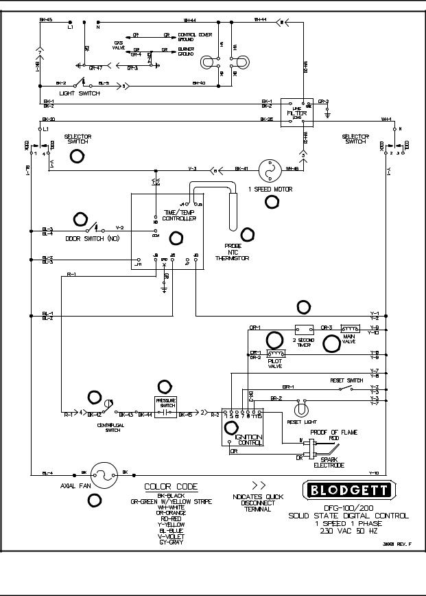
SOLID STATE DIGITAL
SEQUENCE OF OPERATION - DIAGRAM P/N 31981 REV F
NOTE: Refer to FIGURE 8 page 2-9 for compo nent locations.
Component Reference
1.MODE SWITCH
2.DOOR SWITCH
3.TIME AND TEMPERATURE CONTROL
4.AXIAL FAN
5.SINGLE SPEED MOTOR
6.CENTRIFUGAL SWITCH
7.PRESSURE SWITCH
8.LANDIS & GYR IGNITION CONTROL
9.2 SECOND TIMER
10.A & B DUAL SOLENOID GAS VALVE
11.TEMPERATURE PROBE
Operation
1.Power is applied to terminals L1 and N of the mode selector switch (1).
2.If the mode selector switch is set to cook, 230VAC is sent to one side of a SPST door switch (2), terminals J11 and J8 of the time and temperature control (3) and the axial cooling fan (4).
3.If the doors are closed the door switch (2) should be closed sending 230VAC to the con) vection fan motor (5).
NOTE: The door switch is located behind the combustion cover and is operated by the cam mounted on the right hand hinge pin.
NOTE: The motor only operates continuously if the control is not set for pulse. If there is a time programmed into the control for pulse the control opens and closes a set of contacts on the control to cycle the fan on and off.
4.If there is a temperature programmed into the time and temperature control (3) and the control is calling for heat as sensed by the RTD probe (11), 230VAC is applied to one side of a centrifu) gal switch (6) in the convection motor (5).
NOTE: The temperature probe has a de scending temperature coefficient.
NOTE: The centrifugal switch is an integral part of the convection blower and is not field repairable.
5.If the motor (5) is up to full speed the centrifugal switch (6) should be closed sending power to the pressure switch (7). If the pressure switch is closed, 230VAC is applied to the Landis & Gyr ignition module (8).
6.This ignition module is used for direct spark application. This appliance utilizes a two sec) ond timer (9) wired in parallel with the pilot valve (10a) to keep power from going to the main valve (10b) for two seconds after the pilot is lit.
2-8
DFG 100 and DFG 200 |
|
|
1 |
|
|
|
5 |
|
2 |
|
|
3 |
11 |
|
|
|
|
|
|
9 |
|
10A |
10B |
|
|
|
7 |
|
|
6 |
|
|
|
8 |
|
4 |
|
|
FIGURE 8
2-9

OPERATION
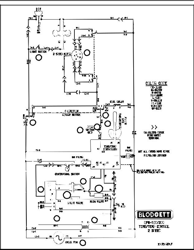
SEQUENCE OF OPERATION - DIAGRAM P/N 30073 REV F
NOTE: Refer to FIGURE 9 page 2-11 for compo nent locations.
Component Reference
1.MODE SWITCH
2.LIGHT SWITCH
3.TIME AND TEMPERATURE CONTROL
4.TRANSFORMER
5.AXIAL FAN
6.TWO SPEED MOTOR
7.TEMPERATURE PROBE
8.CENTRIFUGAL SWITCH
9.IGNITION CONTROL MODULE
10.A & B DUAL SOLENOID GAS VALVE
11.PILOT BURNER
12.DOOR SWITCH
Operation
1.Power is applied to the appliance by a 110 volt power cord attached to the rear of the oven.
2.Power is at L1 and N of the mode selector switch (1).
3.Power is also applied to one side of a SPST light switch (2).
4.When the mode selector switch (1) is set to the cook position a circuit is made between N and terminal 3 as well as L1 and terminal 4 or 1 de) pending on which motor operation is selected.
NOTE: The mode selector switch in this ap plication is a four position selector switch and allows for hi and low speed fan operation.
5.Power is delivered to the common terminal and terminal J8 of the time and temperature con) troller (3), the primary side of a 110 to 24 volt transformer (4) and to an axial cooling fan (5). When the transformer is powered up 24VAC is delivered to terminals 6 and 2 of the ignition control module (9). After the ignition control module has completed a diagnostic and all functions check out, 24VAC is sent to the pilot valve (10a) and a high energy spark jumps a gap at the pilot burner (11). Once the pilot is lit and the pilot flame is proven the ignition control module (9) sends 24VAC to the centrifugal switch (8) in the convection fan (6).
6.If the doors are closed, the door switch (12) should be closed sending 110VAC to the con) vection fan motor (6).
NOTE: The door switch is located behind the combustion cover and is operated by the cam that is mounted on the right hand hinge pin.
NOTE: The motor will only operate continu ously if the control is not set for pulse. If there is a time programmed into the control for pulse the control opens and closes a set of contacts on the the con trol to cycle the fan on and off.
NOTE: The centrifugal switch is an integral part of the convection blower and is not field repairable.
7.If the motor (6) is up to full speed, the centrifu) gal switch (8) closes sending 24VAC to termi) nal J11 of the temperature control (3).
8.If there is a temperature programmed into the time and temperature control (3) and the con) trol is calling for heat as sensed by an RTD probe (7), a circuit is completed between J9 and J11 of the time and temperature control (3) allowing 24VAC to go to the main valve (10b).
NOTE: The temperature probe has a de scending temperature coefficient.
2-10
DFG 100 and DFG 200 |
|
|
6 |
2 |
|
|
1 |
1 |
7 |
|
|
|
3 |
|
12 |
|
11 |
9 |
10b |
10a |
|
8 |
4 |
|
|
|
5 |
FIGURE 9
2-11

OPERATION
FAN DELAY WITH PULSE PLUS
SEQUENCE OF OPERATION - DRAWING P/N 20029 REV A
Component Reference
NOTE: Refer to FIGURE 10 page 2-14 for compo nent locations.
1.MODE SELECTOR
2.TEN MINUTE FAN DELAY TIMER
3.TEMPERATURE CONTROL BOARD
4.AXIAL FAN
5.PULSE TIMER
6.TRANSFORMER
7.DOOR SWITCH
8.TWO SPEED MOTOR
9.CENTRIFUGAL SWITCH
10.IGNITION CONTROL
11.TEMPERATURE PROBE
12.A & B DUAL SOLENOID GAS VALVE
13.COOK TIMER
14.TPDT RELAY
15.TPDT SWITCH
16.LIGHT BULBS
17.LIGHT SWITCH
18.BUZZER
Operation
1.Power is applied to the appliance by a 110 volt power cord attached to the rear of the oven.
2.Power is at L1 and N of the mode selector switch (1).
3.If the mode switch (1) is turned on, a circuit is made between L1-1 and N-2, allowing cur) rent to flow to terminal 1 of the fan delay timer (2), terminal #8 of the solid state temperature control board (3) and the axial fan (4).
4.If the fan delay timer (2) is not counting down, a circuit is made between terminals 1 and 4 al) lowing voltage to go to terminal 3 of the pulse timer (5), one side of a SPST door switch (7), terminal 1 of the cook timer (13) and the prima) ry side of a 110 to 24 volt transformer (6).
5.If the doors are closed the door switch (7) should be closed sending power to the con) vection blower (8). When this motor reaches full speed, a centrifugal switch (9) closes send) ing 24VAC to terminal 6 of the temperature control board (3) and the ignition control mod) ule (10).
NOTE: The door switch is located behind the combustion cover and is operated by the cam that is mounted on the right hand hinge pin.
NOTE: The centrifugal switch is an integral part of the convection blower and is not field repairable.
6.On a call for heat from the thermostat as sensed by an RTD probe (11) a set of contacts on the temperature control board (3) close completing a circuit to terminal 2 of the ignition control module (10).
NOTE: The thermostat consists of three com ponents (RTD probe, solid state tem perature control board and a 1000 ohm potentiometer).
NOTE: The temperature probe has a de scending temperature coefficient.
7.After the ignition control module (10) has com) pleted a diagnostics and all functions check out, 24VAC is sent to the pilot valve (12a) and a high energy spark jumps a gap at the pilot burner. When the pilot is lit and the pilot flame is proven, the ignition control module (10) sends 24VAC to the main valve (12b).
NOTE: A 24VAC indicator light is wired in par allel with the main valve to inform the operator that the main gas valve is be ing powered up. The light goes out when the thermostat is satisfied.
2-12
 Loading...