


MT3870
CONVEYOR OVEN
SERVICE AND REPAIR MANUAL
BLODGETT OVEN COMPANY
www.blodgettcorp.com
50 Lakeside Avenue, Box 586, Burlington, Vermont 05402 USA Telephone (802) 658)6600 Fax: (802)864)0183
PN M7489 Rev B (6/01)
E 1996 - G.S. Blodgett Corporation All rights reserved.
Duplication of the information in this manual is prohibited without the consent of the Blodgett Service Department.
|
|
TABLE OF CONTENTS |
|
|
|
|
|
1. |
INTRODUCTION |
|
|
|
Oven Specifications . . . . . . . . . . . . . . . . . . . . . . . . . . . . . . . . . . . . . . . . |
. . . . . . . . . . . . . . . . . . . . . . . 1-1 |
|
|
Ventilation Requirements . . . . . . . . . . . . . . . . . . . . . . . . . . . . . . . . |
. . . . . . . . . . . . . . . . . . . . . . . 1-1 |
|
|
Electrical Specifications . . . . . . . . . . . . . . . . . . . . . . . . . . . . . . . . . . |
. . . . . . . . . . . . . . . . . . . . . . 1-1 |
|
|
Gas Specifications . . . . . . . . . . . . . . . . . . . . . . . . . . . . . . . . . . . . . . |
. . . . . . . . . . . . . . . . . . . . . . 1-2 |
|
|
Illustrated Parts Lists . . . . . . . . . . . . . . . . . . . . . . . . . . . . . . . . . . . . . . . . |
. . . . . . . . . . . . . . . . . . . . . . 1-3 |
|
2. |
ASSEMBLY |
|
|
|
Oven Assembly Procedures . . . . . . . . . . . . . . . . . . . . . . . . . . . . . . . . . . |
. . . . . . . . . . . . . . . . . . . . . . 2-1 |
|
|
Return Air Diverters . . . . . . . . . . . . . . . . . . . . . . . . . . . . . . . . . . . . . |
. . . . . . . . . . . . . . . . . . . . . . 2-1 |
|
|
Air Nozzles . . . . . . . . . . . . . . . . . . . . . . . . . . . . . . . . . . . . . . . . . . . . . |
. . . . . . . . . . . . . . . . . . . . . . 2-1 |
|
|
Conveyor Rack Assemblies . . . . . . . . . . . . . . . . . . . . . . . . . . . . . . |
. . . . . . . . . . . . . . . . . . . . . . 2-1 |
|
|
Wire Conveyor Belt . . . . . . . . . . . . . . . . . . . . . . . . . . . . . . . . . . . . . . |
. . . . . . . . . . . . . . . . . . . . . . 2-1 |
|
|
Drive Chain . . . . . . . . . . . . . . . . . . . . . . . . . . . . . . . . . . . . . . . . . . . . |
. . . . . . . . . . . . . . . . . . . . . . 2-2 |
|
|
Air Plates . . . . . . . . . . . . . . . . . . . . . . . . . . . . . . . . . . . . . . . . . . . . . . |
. . . . . . . . . . . . . . . . . . . . . . 2-2 |
|
|
End Plugs . . . . . . . . . . . . . . . . . . . . . . . . . . . . . . . . . . . . . . . . . . . . . . |
. . . . . . . . . . . . . . . . . . . . . . 2-2 |
|
|
Conveyor Belt Tensioners . . . . . . . . . . . . . . . . . . . . . . . . . . . . . . . . |
. . . . . . . . . . . . . . . . . . . . . . 2-2 |
|
|
Crumb Pans . . . . . . . . . . . . . . . . . . . . . . . . . . . . . . . . . . . . . . . . . . . . |
. . . . . . . . . . . . . . . . . . . . . . 2-2 |
|
|
Mount Remote Control . . . . . . . . . . . . . . . . . . . . . . . . . . . . . . . . . . . |
. . . . . . . . . . . . . . . . . . . . . . 2-2 |
|
|
False Front (If Applicable) . . . . . . . . . . . . . . . . . . . . . . . . . . . . . . . . |
. . . . . . . . . . . . . . . . . . . . . . 2-2 |
|
3. |
OPERATION |
|
|
|
Computer Controller . . . . . . . . . . . . . . . . . . . . . . . . . . . . . . . . . . . . . . . . |
. . . . . . . . . . . . . . . . . . . . . . 3-1 |
|
|
Control Description . . . . . . . . . . . . . . . . . . . . . . . . . . . . . . . . . . . . . . |
. . . . . . . . . . . . . . . . . . . . . . 3-1 |
|
|
Control Operation . . . . . . . . . . . . . . . . . . . . . . . . . . . . . . . . . . . . . . . |
. . . . . . . . . . . . . . . . . . . . . . 3-1 |
|
|
Programming Procedures . . . . . . . . . . . . . . . . . . . . . . . . . . . . . . . . |
. . . . . . . . . . . . . . . . . . . . . . 3-2 |
|
|
Display Information . . . . . . . . . . . . . . . . . . . . . . . . . . . . . . . . . . . . . . |
. . . . . . . . . . . . . . . . . . . . . . 3-2 |
|
|
Sequence of Operation . . . . . . . . . . . . . . . . . . . . . . . . . . . . . . . . . . . . . . |
. . . . . . . . . . . . . . . . . . . . . . 3-3 |
|
|
Domestic and General Export Ovens . . . . . . . . . . . . . . . . . . . . . . |
. . . . . . . . . . . . . . . . . . . . . . 3-3 |
|
|
CE Ovens . . . . . . . . . . . . . . . . . . . . . . . . . . . . . . . . . . . . . . . . . . . . . . |
. . . . . . . . . . . . . . . . . . . . . . 3-5 |
|
|
Oven Adjustments for Cooking . . . . . . . . . . . . . . . . . . . . . . . . . . . . . . . |
. . . . . . . . . . . . . . . . . . . . . . 3-7 |
|
|
Temperature . . . . . . . . . . . . . . . . . . . . . . . . . . . . . . . . . . . . . . . . . . . . |
. . . . . . . . . . . . . . . . . . . . . . 3-7 |
|
|
Conveyor Speed Time vs. Temperature . . . . . . . . . . . . . . . . . . . . |
. . . . . . . . . . . . . . . . . . . . . . 3-7 |
|
|
Air Flow Adjustments . . . . . . . . . . . . . . . . . . . . . . . . . . . . . . . . . . . . |
. . . . . . . . . . . . . . . . . . . . . . 3-7 |
|
4. |
CALIBRATION AND ADJUSTMENT |
|
|
|
Convection Blower Motors . . . . . . . . . . . . . . . . . . . . . . . . . . . . . . . . . . . |
. . . . . . . . . . . . . . . . . . . . . . 4-1 |
|
|
To check motor rotation . . . . . . . . . . . . . . . . . . . . . . . . . . . . . . . . . . |
. . . . . . . . . . . . . . . . . . . . . . 4-1 |
|
|
To check low)limit . . . . . . . . . . . . . . . . . . . . . . . . . . . . . . . . . . . . . . . |
. . . . . . . . . . . . . . . . . . . . . . 4-1 |
|
|
Regulated Gas Pressure . . . . . . . . . . . . . . . . . . . . . . . . . . . . . . . . . . . . . |
. . . . . . . . . . . . . . . . . . . . . . 4-2 |
|
|
Computer Control Configuration . . . . . . . . . . . . . . . . . . . . . . . . . . . . . . |
. . . . . . . . . . . . . . . . . . . . . . 4-3 |
|
|
Temperature Calibration . . . . . . . . . . . . . . . . . . . . . . . . . . . . . . . . . . . . . |
. . . . . . . . . . . . . . . . . . . . . . 4-5 |
|
|
|
|
|
i

TABLE OF CONTENTS
|
Belt Speed Calibration . . . . . . . . . . . . . . . . . . . . . . . . . . . . . . . . . . . . . . . . . . . . . . . . . . . . . . . . . . . . |
4-6 |
|
Closed Loop System . . . . . . . . . . . . . . . . . . . . . . . . . . . . . . . . . . . . . . . . . . . . . . . . . . . . . . . . . . |
4-6 |
|
Open Loop System - Single belt . . . . . . . . . . . . . . . . . . . . . . . . . . . . . . . . . . . . . . . . . . . . . . . |
4-7 |
|
Open Loop System - Twin Belt . . . . . . . . . . . . . . . . . . . . . . . . . . . . . . . . . . . . . . . . . . . . . . . . . |
4-8 |
|
motor control Board Adjustment . . . . . . . . . . . . . . . . . . . . . . . . . . . . . . . . . . . . . . . . . . . . . . . . |
4-9 |
|
Rerating the Appliance . . . . . . . . . . . . . . . . . . . . . . . . . . . . . . . . . . . . . . . . . . . . . . . . . . . . . . . . . . . . |
4-11 |
|
Checking the Firing Rate . . . . . . . . . . . . . . . . . . . . . . . . . . . . . . . . . . . . . . . . . . . . . . . . . . . . . . . |
4-12 |
5. |
TROUBLESHOOTING |
|
|
DC Drive System . . . . . . . . . . . . . . . . . . . . . . . . . . . . . . . . . . . . . . . . . . . . . . . . . . . . . . . . . . . . . . . . . |
5-1 |
|
Computer Control System . . . . . . . . . . . . . . . . . . . . . . . . . . . . . . . . . . . . . . . . . . . . . . . . . . . . . . . . . |
5-2 |
|
Heating System . . . . . . . . . . . . . . . . . . . . . . . . . . . . . . . . . . . . . . . . . . . . . . . . . . . . . . . . . . . . . . . . . . |
5-3 |
|
Convection System . . . . . . . . . . . . . . . . . . . . . . . . . . . . . . . . . . . . . . . . . . . . . . . . . . . . . . . . . . . . . . . |
5-5 |
6. |
TECHNICAL APPENDIX |
|
|
Intermittent Ignition System . . . . . . . . . . . . . . . . . . . . . . . . . . . . . . . . . . . . . . . . . . . . . . . . . . . . . . . . |
6-1 |
|
Principles of Operation . . . . . . . . . . . . . . . . . . . . . . . . . . . . . . . . . . . . . . . . . . . . . . . . . . . . . . . . . |
6-1 |
|
Service Procedures . . . . . . . . . . . . . . . . . . . . . . . . . . . . . . . . . . . . . . . . . . . . . . . . . . . . . . . . . . . |
6-2 |
|
Servicing the Invent Hood . . . . . . . . . . . . . . . . . . . . . . . . . . . . . . . . . . . . . . . . . . . . . . . . . . . . . . . . . |
6-4 |
|
Illustrated Parts List . . . . . . . . . . . . . . . . . . . . . . . . . . . . . . . . . . . . . . . . . . . . . . . . . . . . . . . . . . . |
6-4 |
|
Cleaning and Maintenance . . . . . . . . . . . . . . . . . . . . . . . . . . . . . . . . . . . . . . . . . . . . . . . . . . . . . |
6-5 |
|
Servicing Access . . . . . . . . . . . . . . . . . . . . . . . . . . . . . . . . . . . . . . . . . . . . . . . . . . . . . . . . . . . . . . |
6-6 |
|
Pressure Conversion . . . . . . . . . . . . . . . . . . . . . . . . . . . . . . . . . . . . . . . . . . . . . . . . . . . . . . . . . . . . . . |
6-7 |
|
Conversion Factors . . . . . . . . . . . . . . . . . . . . . . . . . . . . . . . . . . . . . . . . . . . . . . . . . . . . . . . . . . . . . . . |
6-9 |
|
Cooking Computer - Temperature vs Resistance . . . . . . . . . . . . . . . . . . . . . . . . . . . . . . . . . . . . |
6-10 |
ii
Literature Addendum
Operation - Cooking Computer without Conveyor Control
NOTE: This addendum applies to tandem ovens only.
CONTROL DESCRIPTION |
|
|
|
|
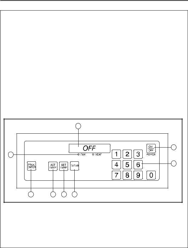
1. |
DIGITAL DISPLAY - Displays the time, tem) |
|
NOTE: |
|
|
perature and controller related information. |
|
|
|
|
|
|
|
|
2. |
OVEN ON/OFF - Controls power to the |
|
This oven, supplied with remote |
|
|
control, is equipped with an emer: |
|
||
|
oven. |
|
|
|
3. |
NUMERIC KEYS - Used to enter numerical |
|
gency shut down switch. |
|
|
|
|
||
|
data in the programming mode. |
|
Should you need to stop the heat |
|
4. |
CLEAR KEY - Used to clear the display if an |
|
press the emergency switch. |
|
|
error is made in the programming mode. |
|
WARNING: |
|
5. |
SET TEMP KEY - Used to view or program |
|
|
|
|
Do not use the emergency switch as |
|
||
|
the temperature setpoint. |
|
|
|
6. |
ACT TEMP KEY - Used to view the current |
|
a GENERAL on/off switch! |
|
|
|
|
||
|
oven temperature. |
|
|
|
|
|
|
|
|
|
|
|
|
|
7.PROG/ENTER KEY - Used to enter and exit the programming mode. Also used to lock in programmed settings.
8.STATUS LAMPS - When lit indicate that the fan or burners are operating.
|
|
|
1 |
|
|
|
2 |
8 |
|
|
|
|
|
|
3 |
7 |
6 |
5 |
4 |
??????
Rev - 10/9/96 Page 1 of 3

Literature Addendum
Operation - Cooking Computer without Conveyor Control
OPERATION
To turn the oven on:
1.Turn the manual gas valve to ON.
2.Press and hold the ON/OFF key (2). The dis) play reads OFF when the oven is idle.
3.The display will flash WAIT D LOW D SET D
TIME D 0.
4.The FAN and HEAT status lamps (9) light. The fans begin to run. The heat rises to the temperature setting stored in the comput) er's memory. The conveyor default time is 0.
To display the actual oven temperature:
1.Press the ACT TEMP key (6). The LED on the key will light and the display reads AC" TUAL D nnnn_F.
To view the temperature set point:
1.Press the SET TEMP key (5). The LED on the key will light and the display flashes SET D
TEMP D nnnn_F.
To turn the oven off:
1.Press the ON/OFF key (2). The fans will con) tinue to run until the oven cools to a safe temperature.
OVEN SHUT:DOWN
Turn the Computer Controller off (press and mo) mentarily hold the ON/OFF key). Since the Cool Down circuit is already energized, the blower motor(s) will continue to run until the oven reaches approximately180_F (82_C). The blow) er motor(s) will then automatically shut off.
COOL:DOWN CIRCUIT
Blodgett Masterthermr conveyor ovens are equipped with a cool)down feature for motor shaft and bearing protection. When the oven reaches approximately 180_F (82_C), the relay contacts close allowing the blower motor(s) to continue to run regardless of the Computer Controller status. As noted previously, the blow) er(s) will continue to run until the temperature drops below 180_F (82_C).
NOTE:
This oven, supplied with remote control, is equipped with an emer: gency shut down switch.
Should you need to stop the heat press the emergency switch.
WARNING:
Do not use the emergency switch as a GENERAL on/off switch!
2 |
M7260.1 |
Rev - 9/5/96 |

Literature Addendum
Operation - Cooking Computer without Conveyor Control
PROGRAMMING PROCEDURES
Programming the Cook Time:
1. The conveyor belt default time is 0.
Programming the Temperature:
1.Press the PROGRAM/ENTER key (8).
2.Press the SET TEMP key (5). The display reads PROG"? D SET D TEMP"? D _ _ _ __F.
3.Use the NUMERIC keys (3) to enter the de) sired temperature set point. The control dis) plays the numbers as they are entered. If an error is made, press the CLEAR key (4) and re)enter the number.
4.Press the PROGRAM/ENTER key (8) again.
5.Press the PROGRAM/ENTER key (8) a sec) ond time to lock)in the new temperature. The new temperature setpoint will be stored in the computer's memory.
Operation at the Programmed Settings:
1.Press and hold the ON/OFF key (2).
2.The FAN and HEAT status lamps (9) light. The fans begin to run. The heat rises to the temperature setting stored in the comput) er's memory.
3.The display will flash WAIT D LOW D SET D TIME D 0 until the programmed bake temper) ature is reached. The HEAT lamp (9) will re) main lit until the oven reaches the tempera) ture set point.
4.The display reads READY and the HEAT lamp (9) goes out.
5.The oven is now ready to accept product.
6.Press and hold the ON/OFF key (2) to turn the oven off. The fans continue to run while the oven cools to a safe temperature.
DISPLAY INFORMATION
DWAIT D LOW - indicates that the present oven temperature is lower than the set point tem) perature. When the oven reaches the set point temperature the display changes to
READY.
DREADY - indicates that the oven is ready to accept product.
DSET D TIME D 0 - indicates the current cook time setting.
DHIGH D TIME - indicates that the temperature is well above the set point. This usually occurs when moving from a higher toG a lower temper) ature. Wait until the display reads ready be) fore loading product.
DHIGH D TEMP D LIMIT - indicates that the oven temperature exceeds the high limit. The Over Temperature Alarm buzzer will sound. Shut the oven off and wait for the unit to cool down.
DHIGH D TEMP D PANEL - indicates that the control area reaches an excessive tempera) ture. Shut the oven off and wait for the unit to cool down.
DPROBE D OPEN D PROBE D SHORT - indicates that the temperature sensor has failed. The Alarm buzzer sounds. Shut the oven off and contact a service representative.
NOTE:
This oven, supplied with remote control, is equipped with an emer: gency shut down switch.
Should you need to stop the heat press the emergency switch.
WARNING:
Do not use the emergency switch as a GENERAL on/off switch!
??????
Rev - 10/9/96 Page 3 of 3

CHAPTER 1
INTRODUCTION

MT3870
OVEN SPECIFICATIONS
VENTILATION REQUIREMENTS
The hood should completely cover the unit with an overhang of at least 6" (15 cm) on all sides not adja) cent to a wall. The distance from the floor to the lower edge of the hood should not exceed 7' (2.1 m). The ventilation system should replace 80% of the exhaust volume with fresh make up air. TABLE 1 should be used as a guideline.
|
Single |
Double |
Triple |
|
|
|
|
CFM |
1200)1650 |
2400)3300 |
3600)5000 |
|
|
|
|
M3/min |
34 ) 47 |
68)93 |
102)142 |
TABLE 1
Installations within the U.S.
The MT3870 requires a 15 Amp, 60HZ, 1F, 208)240VAC, 4 wire service consisting of L1, L2, neutral and ground. See FIGURE 1. Use 90_C wire and size to National Electric or local codes.
Installations outside the U.S.
The MT3870 requires a 15 Amp, 50Hz, 1F, 230 VAC, 3 wire service consisting of L1, neutral and ground. See FIGURE 1. Use 90_C wire and size wire according to local codes.
CE approved installations
Connect the oven to a separate group 230V, 50 hz with rigid connection and circuit breaker. The cir) cuit breaker should disconnect all poles, including neutral with a contact separation of at least 3 mm.
ELECTRICAL SPECIFICATIONS
NOTE: Three Phase hookup is not permitted.
WARNING: DO NOT INSTALL A •HIGH LEG" TO ANY CONVEYOR OVEN!
NOTE: The burner control unit is phase sensitive. If the phase and neutral are switched the control locks out.
Connect exhaust fan connector 1 and 2. See FIGURE 1. Connect phase + neutral + ground.
|
L1 |
|
|
|
L1 |
|
|
|
N |
120 |
|
|
|
|
|
|
208)240 |
|
N |
220)230 |
|
||
|
|
|
Supply |
Oven |
|||
Supply |
L2 |
120 |
Oven |
|
|
U.S. Installations |
Export Installations |
|
|
2)4)92
L3
L2
L1
N
Blodgett |
N |
|
2 |
s |
A1 |
|
Connector |
L |
|
|
|||
|
|
|
|
|||
|
|
Connector |
1 |
A2 |
|
|
|
|
2 |
|
|
||
|
|
|
|
|
||
|
|
|
|
Fan |
|
Relay A |
2 |
Air Pressure Regulator |
|
1 |
|||
|
|
|||||
|
|
|
||||
1 |
Burner Control Solenoid |
|
|
|
||
CE Approved Installations
FIGURE 1
1-1

INTRODUCTION
GAS SPECIFICATIONS
GAS CONNECTIONS
Domestic and General Export installations
The gas line should be large enough to accommo) date the peak demand of all the gas appliances. TABLE 2 reflects a straight line, 50 foot run with no coupling restrictions and no other appliances drawing service. Gas line installations MUST con) form to National Fuel Gas Code NFPA 54/ANSI Z223.1 Sec. 1.4 (Latest Edition). TABLE 2 should be used as a guideline only.
NOTE: For any pipe runs over 50 feet (15 m), con" sult the factory.
CE approved installations
1.Connect the oven to the gas line with the prop) er type of gas according to Local and National Installation Standards. See TABLE 2.
GAS REQUIREMENTS
The firing rate for the MT3870 is 150,000 BTU/Hr. (43.9 kW/Hr.)
NOTE: For natural gas meter sizing, consult your local gas company to ensure that your me" ter will provide the proper supply.
Installations within the U.S.
1.Add the total BTU's/hr of all the gas appliances.
2.Convert BTU's to cubic ft/hr using the formula Cu Ft/Hr = 1000 BTU/Hr for natural gas.
3.Size the meter accordingly.
Installations outside the U.S.
1.Add the total M3/min of all the appliances.
2.Size the meter accordingly.
DOMESTIC AND GENERAL EXPORT
|
|
Natural Gas |
|
|
Propane Gas |
|
||||
|
|
|
|
|
|
|
|
|
|
|
Gas Line Sizing |
|
|
|
|
|
|
|
|
|
|
Single |
|
|
3/4" line |
|
|
|
3/4" line |
|
||
Double |
|
|
1)1/4" line |
|
|
|
1I line |
|
||
Triple |
|
|
1)1/4" line |
|
|
|
1)1/4" line |
|
||
|
|
|
|
|
|
|
|
|
|
|
Orifice Size |
|
#1 |
|
|
|
#29 |
|
|
||
|
|
|
|
|
|
|
|
|
|
|
Incoming Gas Pressure |
W.C. |
|
kPa |
|
mbar |
W.C. |
|
kPa |
|
mbar |
|
|
|
|
|
|
|
|
|
|
|
Static |
7" |
|
1.74 |
|
17.4 |
12.5" |
|
3.11 |
|
31.1 |
Operational |
5.5" |
|
1.36 |
|
13.7 |
11" |
|
2.73 |
|
27.4 |
|
|
|
|
|
|
|
|
|
|
|
CE APPROVED UNITS
Type of |
Inlet |
Burner Pressure |
Injector |
Air |
Pilot |
Standard |
Gas |
Pressure |
mbars |
Diameter |
Opening |
Injector |
Delivery |
|
mbars |
|
mm |
mm |
mm |
Value kW (HS) |
G25 |
25 |
12 |
5,80 |
16 |
2 x 0,63 |
46 Nat. Gas |
|
|
|
|
|
|
|
G20 |
20 |
8 |
5,80 |
16 |
2 x 0,63 |
46 Nat. Gas |
|
|
|
|
|
|
|
G20/G25 |
20/25 |
Totally Inscrewed |
5,15 |
16 |
2 x 0,63 |
46 Nat. Gas |
|
|
Pressure Regulator |
|
|
|
|
|
|
|
|
|
|
|
G30 |
30/50 |
17 |
3,48 |
16 |
2 x 0,30 |
46 Butane |
|
|
|
|
|
|
|
G31 |
30/37/50 |
24 |
3,48 |
16 |
2 x 0,30 |
46 Propane |
TABLE 2
1-2

MT3870
ILLUSTRATED PARTS LISTS
ELECTRICAL COMPONENTS
NOTE: n = ASAP Distributor Required Stocking Parts
Ref. |
Part |
|
Ref. |
Part |
|
No. |
No. |
Description |
No. |
No. |
Description |
|
|
|
|
|
|
1 |
n M6474 |
Computer Control Kit, Closed |
8 |
n M3295 |
Thermostat, High Limit |
|
|
Loop SB (Qty 1) |
|
|
(Manual Reset) (Qty 1) |
1 |
n FW525 |
Computer Control Kit, Closed |
9 |
n M1362 |
Snap Disc, L140/20F, 2 Pole |
|
|
Loop SB (Qty 1) |
|
|
SPST (Qty 1) |
|
|
(Reconditioned) |
|
n M2453 |
Snap Disc, L140/20F, 3 Pole |
|
M5635 |
Computer Control Kit, Open |
|
||
|
|
|
SPDT (Qty 1) |
||
|
|
Loop TB (Qty 1) |
10 |
n M0595 |
Switch, Air Pressure SPDT |
|
M3175 |
Decal, Lexan Control (Qty 1) |
|||
|
|
|
(Qty 1) |
||
|
n M7427 |
Probe, Temperature RTD, 500 |
11 |
n M0152 |
Contact, Emergency Stop |
|
|
OHMS (Qty 1) |
|||
|
|
|
|
Switch (Qty 1) |
|
|
|
|
|
|
|
|
M7202 |
Conversion Kit, Open Loop to |
12 |
M3296 |
Activator, Emergency Stop |
|
|
Closed Loop (Qty 1) |
|||
|
|
|
|
Switch (Mushroom Shape) |
|
|
|
|
|
|
|
|
M3347 |
Cable, Computer Control, 25 |
|
|
(Qty 1) |
|
|
Pin, 10' (Qty 1) |
|
M3297 |
Nameplate, Emergency Stop |
|
|
|
|
||
|
n M3348 |
Cable, Computer Control, 9 |
|
|
(Qty 1) |
|
|
Pin, 10' (Qty 1) |
13 |
M0593 |
Terminal Block, 2 Pole (Qty 1or |
|
M3490 |
Cable, Computer Control, 25 |
|||
|
|
|
CE Qty 2) |
||
|
|
Pin, 50' (Qty 1) |
|
n M2469 |
Fan, Axial 110 CFM 4 1/2" (Qty |
|
M3491 |
Cable, Computer Control, 9 |
|
||
|
|
|
4) (Before 11/14/95) |
||
|
|
Pin, 50' (Qty 1) |
|
22718 |
Fan Guard & Hardware (Qty 3) |
|
n M3349 |
Harness, Inter-Connecting DC |
|
||
|
|
|
(Before 11/14/95) |
||
|
|
Drive, 3-Wire (For 9 Pin) |
|
|
|
|
|
|
n M0572 |
Cord, Axial Fan 30" Power (Qty |
|
|
|
(Qty 1) |
|
||
|
|
|
|
4) (Before 11/14/95) |
|
|
M3353 |
Harness, Relay Board |
|
|
|
|
14 |
n M6381 |
Blower, Cooling (Qty 1) (After |
||
|
|
(Open Loop) (For 25 Pin) |
|||
|
|
|
|
11/14/95) |
|
|
|
(Qty 1) (Before 9/15/95) |
|
|
|
|
|
|
|
|
|
|
M7237 |
Harness, Relay Board (Closed |
15 |
n M3136 |
Breaker, 7 AMP Circuit (Qty 4) |
|
|
|
|
||
|
|
Loop) (For 25 Pin) (Qty 1) |
16 |
n M2772 |
Breaker, 4 AMP Circuit (Qty 2) |
|
|
(After 9/15/95) |
|
M6590 |
Plate Assy., Control SB (Qty 1) |
2 |
M3314 |
Bracket, Computer Wall (Qty 1) |
|
||
|
M7482 |
Plate Assy., Control TB (Qty 1) |
|||
|
M5661 |
Bracket Assy., Cable Clamp |
|
||
|
|
M1694 |
Cord Set & Plug Assy., 10 Foot |
||
|
|
(Qty 1) |
|
||
|
|
|
|
(Qty 1) |
|
3 |
n M0984 |
Pick Up, PV-2 (Qty 1) (After |
|
|
|
|
M0772 |
Receptacle, Twist Lock (Qty 1) |
|||
|
|
9/15/95) |
|
||
4 |
M7236 |
Board, Relay/Transformer |
17 |
n M0708 |
Contactor, 3 Pole, 120V Coil |
|
|
(Qty 1) |
|
|
(Qty 1) |
5 |
n 22672 |
Relay, Control (Qty 4) |
18 |
n M3322 |
Hood Interlock, Mechanical |
|
|
|
|
|
(Qty 1) |
6n M3352 Transformer, 120V to 24V
(Qty 1)
7n 20349 Buzzer, 120V (Qty 1)
1-3
INTRODUCTION
CONVEYOR COMPONENTS
NOTE: n = ASAP Distributor Required Stocking Parts * = Item is Too Large for UPS
Ref. |
|
Part |
|
Ref. |
Part |
|
|
No. |
|
No. |
Description |
No. |
No. |
Description |
|
|
|
|
|
|
|
|
|
19 |
|
M6338 |
Belt, Wire S/S (Total Length |
|
* M4433 |
Conveyor (Qty 1) Assy., Idle SB |
|
|
|
|
38" SB (Per Foot) MT3870 18 |
|
|
MT3855G (Before 11/14/95) |
|
|
|
|
FT, MT3855 16 FT) |
|
* M6777 |
Conveyor MT3855G Assy., |
|
|
|
|
|
|
|||
|
|
M7889 |
Belt, Wire S/S (Total Length |
|
|
Folding (Drive & Idle) SB (Qty |
|
|
|
|
18-1/2" TB (Per Foot) |
|
|
1) (After 11/14/95) |
|
|
|
|
MT3870 18 FT) |
29 |
M2672 Shaft, Conveyor Drive (Qty 1) |
||
|
|
|
|
||||
20 |
|
M7272 |
Tensioner (After Assy., Belt |
30 |
M2673 Shaft, Conveyor Idle (Qty 1) |
||
|
|
|
MT3870 (Qty 2) 9/15/95) |
||||
|
|
|
31 |
nM0109 Sprocket, Motor Drive, 12 Tooth |
|||
21 |
nM2379 |
Speed Control Board, Bodine |
|||||
|
|
(Qty 1) |
|||||
|
|
|
(Qty 1) |
|
|
||
|
|
|
|
nM0110 Sprocket, Conveyor Drive, 15 |
|||
|
nM2254 |
Fuse, Line, 22 Bodine Board, 5 |
|
||||
|
|
|
Tooth (Qty 1) |
||||
|
|
|
AMP, 125V (Qty 1) |
|
|
||
|
|
|
32 |
nM0108 Sprocket, Conveyor Belt, 11 |
|||
|
nM2316 |
Fuse, (Qty 1) 23 Armature, |
|||||
|
|
|
Tooth (Qty 18) |
||||
|
|
|
Bodine Board, 200 MA, 250V |
|
|
||
|
|
|
|
|
|
||
24 |
|
M3301 |
Capacitor, (SB Qty 1 or Speed |
|
|
|
|
|
|
|
Control Board TB Qty 2) |
|
|
|
|
25 |
nM2378 |
Motor, (SB Qty 1 or Conveyor |
|
|
|
||
|
|
|
Drive, Bodine 130V TB Qty 2) |
|
|
|
|
|
nM2500 |
Brush Set, Bodine (Qty 1) |
|
|
|
||
|
|
M0391 |
Chain, Drive & Order (SB Spec) |
|
|
|
|
|
|
|
ify 2 FT or TB Specify 4 FT |
|
|
|
|
|
|
|
M0112) |
|
|
|
|
|
nM0112 |
Masterlink, Drive Chain (Qty 1) |
|
|
|
||
|
|
M6791 |
Guard, Drive 26 Chain SB (Qty |
|
|
|
|
|
|
|
1) |
|
|
|
|
|
|
M6482 |
Guard, Drive Chain TB (Qty 1) |
|
|
|
|
|
* |
M3981 |
Conveyor (Before Assy., Drive |
|
|
|
|
|
|
|
SB MT3870 (Qty 1) 9/15/95) |
|
|
|
|
27 |
* |
M6154 |
Conveyor (After Assy., Drive SB |
|
|
|
|
|
|
|
MT3870 (Qty 1) 9/15/95) |
|
|
|
|
|
* |
M3982 |
Conveyor (Before Assy., Idle |
|
|
|
|
|
|
|
SB MT3870 (Qty 1) 9/15/95) |
|
|
|
|
28 |
* |
M6155 |
Conveyor (After Assy., Idle SB |
|
|
|
|
|
|
|
MT3870 (Qty 1) 9/15/95) |
|
|
|
|
*M7592 Conveyor Assy., Drive TB MT3870 (Qty 1)
*M7593 Conveyor Assy., Idle TB MT3870 (Qty 1)
*M4432 Conveyor (Qty 1) Assy., Drive SB MT3855G (Before 11/14/95)
1-4

MT3870
CONVECTION COMPONENTS
NOTE: n = ASAP Distributor Required Stocking Parts
Ref. |
Part |
|
Ref. |
Part |
|
No. |
No. |
Description |
No. |
No. |
Description |
|
|
|
|
|
|
33 |
nM4224 |
Motor & Blower Assy. CW |
|
M1962 |
Hold Down, Nozzle MT3870 |
|
|
MT3870 (Qty 2) |
|
|
(Qty 1) (Before 9/15/95) |
34 |
nM4225 |
Motor & Blower Assy. CCW |
|
M7399 |
Hold Down, Nozzle MT3870 |
|
|
MT3870 (Qty 2) |
|
|
Qty 1) (After 9/15/95) |
|
M5419 |
Motor & Blower Assy. CCW |
|
M5486 |
Hold Down, Nozzle MT3855G |
|
|
MT3855G (Qty 3) (After |
|
|
(Qty 1) (Before 11/14/95) |
|
|
2/27/94) |
|
M7380 |
Hold Down, Nozzle MT3855G |
|
|
|
|
||
|
M2564 |
Capacitor, Motor MT3870 |
|
|
(Qty 1) (After 11/15/95) |
|
|
(Qty 4) |
36 |
M3106 |
Diverter, Air (LH & RH) MT3870 |
|
|
|
|||
NOTE: Call factory if MT3855G oven was |
|
|
(Qty 2) |
||
|
manufactured before 2/27/94 to verify |
|
M3106 |
Diverter, Air (LH & RH) |
|
|
motor part number. |
|
|||
|
|
|
MT3855G (Qty 2) (Before |
||
|
|
|
|
|
|
|
nM5722 |
Insulation Kit for Blowers |
|
|
11/14/95) |
|
|
MT3870 (Qty 1) |
|
M5179 |
Diverter, Air (LH & RH) |
|
|
|
|
||
|
M7991 |
Insulation Kit for Blowers |
|
|
MT3855G (Qty 2) (Before |
|
|
MT3855G (Qty 1) |
|
|
11/14/95) |
35 |
M6466 |
Nozzle Assy. w/ Diverter |
|
M5453 |
Diverter, Air (Center) MT3855G |
|
|
MT3870 (Qty 14) Generic |
|
|
(Qty 1)(Before 11/14/95) |
|
M5466 |
Nozzle Assy. w/ Diverter |
|
M7372 |
Diverter, Air (LH) MT3855G |
|
|
MT3855G (Qty 12) (Before |
|
|
(Qty 1) (After 11/14/95) |
|
|
11/14/95) |
|
|
(See L-495 & L-496) |
|
M7105 |
Nozzle Assy. w/ Diverter |
|
M7374 |
Diverter, Air (RH) MT3855G |
|
|
MT3855G (Qty 6) (After |
|
|
(Qty 1) (After 11/14/95) |
|
|
11/14/95) (See L-497) |
|
|
(See L-495 & L-496) |
|
M7106 |
Nozzle Assy. w/ Diverter |
|
M7373 |
Diverter, Air (Center) MT3855G |
|
|
MT3855G (Qty 6) |
|
|
(Qty 1) (After 11/14/95) |
|
|
(After 11/14/95) (See L-497) |
|
|
(See L-495 & L-496) |
AIR PLATES |
|
|
|
|
|
NOTE: n = ASAP Distributor Required Stocking Parts |
|
|
|||
|
|
|
|
|
|
Ref. |
Part |
|
Ref. |
Part |
|
No. |
No. |
Description |
No. |
No. |
Description |
|
|
|
|
|
|
37 |
M6470 |
Plate Assy., Air RH MT3870 |
|
M5649 |
Plate Assy., Air LH (L to R) |
|
|
Generic (Qty 1) |
|
|
MT3855G Generic (Qty 1) |
38 |
M6469 |
Plate Assy., Air LH MT3870 |
|
24613 |
Hook, Air Pan (Qty 1) |
|
|
Generic (Qty 1) |
39 |
M6597 |
Plate Assy., Block Off MT3870 |
|
|
|
|||
|
M5767 |
Plate Assy., Air RH (R to L) |
|
|
Generic (Qty 6) |
|
|
MT3855G Generic (Qty 1) |
|
M6079 |
Plate Assy., Block Off MT3855G |
|
|
|
|
||
|
M5768 |
Plate Assy., Air LH (R to L) |
|
|
Generic (Qty 6) |
|
|
MT3855G Generic (Qty 1) |
|
|
|
|
M5648 |
Plate Assy., Air RH (L to R) |
|
|
|
|
|
MT3855G Generic (Qty 1) |
|
|
|
|
|
|
|
|
|
1-5

INTRODUCTION
GAS BURNER COMPONENTS
NOTE: n = ASAP Distributor Required Stocking Parts
Ref. |
Part |
|
Ref. |
Part |
|
No. |
No. |
Description |
No. |
No. |
Description |
|
|
|
|
|
|
40 |
22132 |
Burner Assy. Complete (Specify |
63 |
21278 |
Nipple, Pipe 1/2 x 3-1/2 |
|
|
Model & Gas Type) (Qty 1) |
|
|
(Qty 1) |
41 |
nM0767 |
Blower Motor, Comb. w/ Con) |
64 |
M3238 |
Tee, 1/2 x 1/2 x 1/4 (Qty 1) |
|
|
trol Box (Qty 1) |
65 |
n23007 |
Spring, Solenoid Valve, LP to |
|
|
|
|||
42 |
nM2383 |
Blower Motor, Combustion |
|
|
Natural (Qty 1) |
|
|
(Qty 1) |
65 |
n18612 |
Spring, Solenoid Valve, Natural |
|
|
|
|||
43 |
nM2381 |
Transformer, 120V to 24V |
|
|
to LP (Qty 1) |
|
|
(Qty 1) |
|
23114 |
Conversion Kit, LP to Natural |
|
|
|
|
||
44 |
nM2382 |
Relay, Time Delay (Qty 1) |
|
|
MT3870 (Qty 1) |
45 |
M0454 |
Orifice, Main Burner LP (Qty 1) |
|
n21389 |
Conversion Kit, Natural to LP |
45 |
M0455 |
Orifice, Main Burner Natural |
|
|
MT3870 (Qty 1) |
|
|
|
|||
|
|
(Qty 1) |
|
M5259 |
Conversion Kit, LP to Natural |
46 |
nM2727 |
Pilot Burner & Igniter Assy. LP |
|
|
MT3855G (Qty 1) |
|
|
|
|||
|
|
(Qty 1) |
|
M5290 |
Conversion Kit, Natural to LP |
46 |
nM2726 |
Pilot Burner & Igniter Assy. |
|
|
MT3855G (Qty 1) |
|
|
|
|||
|
|
Natural (Qty 1) |
66 |
nM0282 |
Valve, Manual Gas (Qty 1) |
47 |
M6378 |
Shield, Pilot Burner (Qty 1) |
67 |
nM5495 |
Dual Solenoid/Pressure Regu) |
48 |
nM0415 |
Flame Sensor (Qty 1) |
|
|
lator, Nat 24V (Qty 1) |
|
|
|
|||
49 |
nM2690 |
Orifice, Pilot LP (Qty 1) |
67 |
n22190 |
Dual Solenoid/Pressure Regu) |
|
|
lator, LP 24V (Qty 1) |
|||
|
|
|
|
|
|
49 |
nM0697 |
Orifice, Pilot Natural (Qty 1) |
68 |
nM1054 |
Spark Box, Johnson (Qty 1) |
|
|
|
|||
50 |
M0248 |
Tube, Pilot Aluminum 1/4" |
|
21242 |
Connector Kit, Gas Flex 48" |
|
|
(1.583 Feet) |
|
||
|
|
|
|
(Qty 1) |
|
|
|
|
|
|
|
51 |
M0959 |
Fitting, Compression 1/4 |
|
21826 |
Connector Kit, Gas Flex 36" |
|
|
(Qty 2) |
|
||
|
|
|
|
(Qty 1) |
|
|
|
|
|
|
|
52 |
M2799 |
Union, Compression (Qty 1) |
69 |
M7280 |
Flame Tube Assy., MT3870 |
|
|
|
|||
53 |
21225 |
Fitting, Elbow (Qty 1) |
|
|
(Qty 1) |
54 |
4588 |
Nipple, Pipe 3/4 x 1-3/8 Close |
|
M7390 |
Flame Tube Assy., MT3855G |
|
|
(Qty 3 or CE Qty 2) |
|
|
(Qty 1) |
55 |
M0280 |
Tee, 3/4 x 3/4 x 1/4 (Qty 1) |
|
|
|
56 |
M0278 |
Bushing, 1/4 x 1/8 Hex (Qty 2) |
|
|
|
57 |
M0281 |
Plug, Pipe 1/8 Black (Qty 2) |
|
|
|
58 |
17874 |
Ell, Black 1/2 x 3/4 (Qty 1) |
|
|
|
59 |
M0590 |
Nipple, Pipe 1/2 x 2-1/2 |
|
|
|
|
|
(Qty 1) |
|
|
|
60M0279 Union, 1/2 Inch Black (Qty 1)
611949 Nipple, Pipe 1/2 x 1-3/16
|
Close (Qty 1) |
62 |
M0317 Elbow, 1/2 Inch Street 90 Deg |
|
(Qty 1) |
1-6

MT3870
EXTERIOR COMPONENTS
NOTE: z = Doors are not returnable
Ref. |
Part |
|
Ref. |
Part |
|
No. |
No. |
Description |
No. |
No. |
Description |
|
|
|
|
|
|
|
z M2868 |
Door Assembly, Pull Down S/S |
|
M7575 |
Extension Assy., Product 15" |
|
|
(used w/enclosed Greenheck |
|
|
(LaRosa's) (Qty 1) |
|
|
hood system) (Qty 1) |
|
M2824 |
Crumb Pan, Idle MT3870 |
|
|
|
|
||
|
M2188 |
Handle Kit, Door 2" (used |
|
|
(Qty 1) (Before 9/15/95) |
|
|
w/M2868) (Qty 1) |
79 |
M6168 |
Crumb Pan, Idle MT3870 |
|
|
|
|||
70 |
z M3944 |
Door Assembly (used w/ false |
|
|
(Qty 1) (After 9/15/95) |
|
|
front) (Qty 1) |
|
M2823 |
Crumb Pan, Drive MT3870 |
|
|
|
|
||
71 |
M4275 |
Handle Kit, Door 22" (used w/ |
|
|
(Qty 1) (Before 9/15/95) |
|
|
M3944) (Qty 1) |
80 |
M6167 |
Crumb Pan, Drive MT3870 |
|
|
|
|||
72 |
M1871 |
Plate, RH Pivot Slotted (Qty 1) |
|
|
(Qty 1) (After 9/15/95) |
73 |
M1872 |
Plate, LH Pivot Slotted (Qty 1) |
|
M6910 |
Crumb Pan, Idle MT3855G |
74 |
M3602 |
Bracket Assy., Mounting (Qty 2) |
|
|
(Qty 1) |
|
M6906 |
Crumb Pan, Drive MT3855G |
|||
75 |
M3603 |
Bracket Assy., Mounting (Qty 2) |
|
||
|
|
(Qty 1) |
|||
|
|
|
|
|
|
|
M5475 |
Filter Assy., MT3855G (Qty 1) |
|
M5612 |
Plug Assy., Lower RH MT3870 |
|
|
(Before 11/14/ 95) |
|
||
|
|
|
|
Qty 1) (Before 9/15/95) |
|
|
|
|
|
|
|
76 |
M3751 |
False Front Assy., MT3870 |
81 |
M7276 |
Plug Assy., Lower RH MT3870 |
|
|
(Qty 1) |
|||
|
|
|
|
(Qty 1) (After 9/15/95) |
|
|
|
|
|
|
|
|
M4563 |
False Front Assy., MT3855G |
82 |
M5612 |
Plug Assy., Lower LH MT3870 |
|
|
(Qty 1) |
|||
|
|
|
|
(Qty 1) |
|
|
|
|
|
|
|
|
M3751 |
Tape, Closed Cell Foam |
|
M7386 |
Plug Assy., Lower MT3855G |
|
|
|
|
||
|
M5032 |
Chimney Kit, Single (Qty 1) |
|
|
(Qty 2) |
|
|
(Before 11/95) |
83 |
M3116 |
Plug Assy., Upper MT3870 & |
|
|
|
|||
|
M7464 |
Chimney Kit, Single (Qty 1) |
|
|
MT3855G (Qty 2) |
|
|
(After 11/95) |
84 |
M2460 |
Air Curtain, Upper End Plug |
|
|
|
|||
|
M7160 |
Chimney Kit, Double (Qty 1) |
|
|
(Qty 2) |
|
|
(Before 11/95) |
|
M3728 |
Support Assy., Upper End Plug |
|
|
|
|
||
|
M7463 |
Chimney Kit, Double (Qty 1) |
|
|
RH MT3870 (Qty 2) |
|
|
(After 11/95) |
|
M3729 |
Support Assy., Upper End Plug |
|
|
|
|
||
|
21390 |
Legs, 17-1/4" w/ Casters |
|
|
LH MT3870 (Qty 2) |
|
|
(Double) (Set of 4) |
|
M7149 |
Support Assy., Upper End Plug |
|
|
|
|
||
|
21391 |
Legs, 23-1/4" w/ Casters |
|
M7150 |
RH MT3855G (Qty 2) Support |
|
|
(Single) (Set of 4) |
|
|
Assy., End Plug LH MT3855G |
|
14444 |
Casters, Cradle (Triple Oven) |
|
|
(Qty 2) |
|
|
|
|
||
|
|
(Set of 4) |
85 |
M3724 |
Handle, End Plug (Qty 2) |
77 |
M3783 |
Stop, Product S/S (Qty 1) |
|
22229 |
Stacking Assy., Double (Qty 1) |
78 |
M3779 |
Extension Assy., Product 6" |
|
M4633 |
Panel & Filter Assy. (Qty 1) |
|
|
(Qty 1) |
|
|
MT3870 (All) & MT3855G |
|
M4223 |
Extension Assy., Product 10" |
|
|
(Before 11/14/95) |
|
|
|
|
(Qty 1)
1-7

|
|
|
|
|
INTRODUCTION |
|
|
|
|
|
|
|
|
|
|
|
|
Ref. |
Part |
|
Ref. |
Part |
|
No. |
No. |
Description |
No. |
No. |
Description |
|
|
|
|
|
|
|
M5485 |
Panel & Filter Assy. MT3855G |
86 |
M7266 |
Control Box Cover w/ Access |
|
|
(Qty 1) (After 11/14/95) |
|
|
Door MT3870 (Qty 1) |
|
XXXXX Control Box Cover w/ Louvers |
|
|
(After 9/15/96) |
|
|
|
|
|
||
|
|
MT3855G (Qty 1) (Before |
87 |
M6035 |
Latch, Access Door (Qty 1) |
|
|
11/14/95) |
|
M2689 |
Body Back, MT3870 (Qty 1) |
|
|
|
|
||
|
M6799 Control Box Cover w/ Access |
|
|
(Before 9/15/95) |
|
|
|
Door MT3855G (Qty 1) (After |
|
M7254 |
Body Back, MT3870 (Qty 1) |
|
|
11/14/95) |
|
||
|
|
|
|
(After 9/15/95) |
|
|
|
|
|
|
|
|
XXXXX Control Box Cover w/ Louvers |
|
M4248 |
Body Back, MT3855G (Qty 1) |
|
|
|
MT3870 (Qty 1) (Before |
|
||
|
|
|
|
|
|
|
|
9/15/95) |
|
|
|
1-8

MT3870
EXCLUSIVE TO EXPORT
NOTE: n = ASAP Distributor Required Stocking Parts
Ref. |
Part |
|
Ref. |
Part |
|
No. |
No. |
Description |
No. |
No. |
Description |
|
|
|
|
|
|
88 |
M2276 |
Burner Assy., Complete |
108 |
M2498 |
Switch, Contact (Qty 1) CE |
|
|
(Qty 1) |
109 |
M3330 |
Switch, Air Pressure Differen) |
|
|
|
|||
89 |
M4597 |
Motor & Blower Assy., CW |
|
|
tial (mbr) (Qty 1) CE |
|
|
MT3870 (Qty 2) |
|
M2819 |
Switch, Air Pressure (in/wc) |
|
|
|
|
||
90 |
M4598 |
Motor & Blower Assy., CCW |
|
|
(Qty 1) Australia |
|
|
MT3870 (Qty 2) |
110 |
M0706 |
Orifice, Main Burner (Specify |
|
|
|
|||
91 |
M6000 |
Dual Solenoid/Pressure |
|
|
MTD) (Qty 1) CE |
|
|
Regulator, Nat. (Qty 1) |
111 |
R0164 |
Terminal Block, Power (Qty 2) |
|
|
|
|||
91 |
M6001 |
Dual Solenoid/Pressure |
|
|
CE |
|
|
Regulator, LP (Qty 1) |
112 |
R0166 |
Terminal Block, Ground |
|
|
|
|||
92 |
M7283 |
Blower, Cooling Export (Qty 1) |
|
|
(Qty 1) CE |
93 |
M3128 |
Motor, Conveyor Drive |
113 |
nM3168 |
Spark Box, 240V (Landis & |
|
|
Bodine, 180V (Qty 1) |
|
|
Gyr) (Qty 1) CE |
94 |
M3153 |
Digital Speed Control Board, |
114 |
nM2247 |
Contactor, 240V, 50 HZ (Qty 1) |
|
|
Bodine (Qty 1) |
|
|
CE |
95 |
M2630 |
Fuse, Line, Bodine Board, 500 |
115 |
XXXXX |
Indicator Light (Qty 2) CE |
|
|
MA (Qty 1) |
|
18265 |
Indicator Light, 28V, Red, |
|
|
|
|
||
96 |
nM2316 |
Fuse, Armature, Bodine |
|
|
Round (Qty 1) CE |
|
|
Board, 200 MA, 250V (Qty 1) |
116 |
16037 |
Indicator Light, 250V, Red, |
|
|
|
|||
|
M5717 |
Board, Relay (Open Loop) SB |
|
|
Round (Qty 1) CE & Australia |
|
|
(Qty 1) |
117 |
16775 |
Relay, SPST, 240V, 30 Amp. |
|
|
|
|||
97 |
M7282 |
Board, Relay (Closed Loop) |
|
|
(Qty 1) CE |
|
|
SB (Qty 1) |
118 |
M3172 |
Timer, Fixed, 2 Second (Qty 1) |
|
|
|
|||
98 |
M6025 |
Fuse, 25V 80 ma (Qty 1) |
|
|
CE |
99 |
M6024 |
Transformer, 220V to 24V |
119 |
M3173 |
Timer, Fixed, 10 Second (Qty |
|
|
(Qty 1) |
|
|
1) CE |
100 |
n20350 |
Buzzer, 240V (Qty 1) |
|
M6589 |
Plate Assy., Control SB (Qty 1) |
101 |
R1580 |
Stop, End (Qty 1) |
|
|
CE |
|
|
|
|||
102 |
M6449 |
Filter, Noise (Qty 1) CE |
|
M7323 |
Plate Assy., Control SB Qty 1) |
|
|
Australia |
|||
|
|
|
|
|
|
103 |
M7880 |
Computer Control Kit, Closed |
|
M6982 |
Piping Assy. (Qty 1) CE |
|
|
Loop SB (Qty 1) CE |
|
||
|
|
|
|
|
|
104 |
M7888 |
Relay, 1 Second Time Delay |
120 |
M6029 |
Connector, Liquid Tight (Qty |
|
|
1) CE |
|||
|
|
(Qty 1) CE |
|
|
|
|
|
|
|
|
|
105 |
M2386 |
Blower Motor, Combustion |
121 |
10809 |
Nipple, Pipe 1/2 x 2 (Qty 1) |
|
|
CE |
|||
|
|
(Qty 1) CE |
|
|
|
|
|
|
|
|
|
106 |
M7333 |
Pilot Burner & Ignitor Assy., |
122 |
M2835 |
Fitting, Elbow 90 Street 1/8" |
|
|
(Qty 1) CE |
|||
|
|
LP (Qty 1) CE |
|
|
|
|
|
|
|
|
|
106 |
M7334 |
Pilot Burner & Ignitor Assy., |
123 |
M3443 |
Bushing, Adapter (Qty 2) CE |
|
|
|
|||
|
|
Nat. (Qty 1) CE |
124 |
M2841 |
Fitting, Pressure Tap (Qty 2) |
107 |
M2497 |
Switch, Push Button (Qty 1) |
|
|
CE |
|
|
|
CE
1-9

INTRODUCTION |
MT3870 DOMESTIC & GENERAL EXPORT CONTROL BOX |
(Control Plate and/or Gas Burner Components not Shown) |
1-10 |

MT3870 |
MT3870 CE CONTROL BOX |
(Control Plate and/or Gas Burner Components not Shown) |
1-11 |

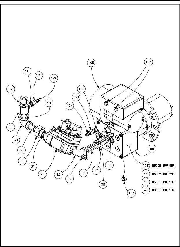
INTRODUCTION |
MT3870 DOMESTIC GAS BURNER COMPONENTS |
(Control Box not Shown) |
1-12 |
MT3870 |
MT3870 CE GAS BURNER COMPONENTS |
(Control Box not Shown) |
1-13 |

INTRODUCTION |
MT3870 DOMESTIC & GENERAL EXPORT SB CONTROL PLATE ASSY |
(M6590) |
1-14 |
 Loading...