


XR8 G and XR8 E
MINI RACK OVEN
INSTALLATION - OPERATION - MAINTENANCE
XR8 G et XR8 E
MINI FOUR DE SUPPORT
MANUEL D'INSTALLATION - FONCTIONNEMENT - ENTRETIEN
BLODGETT OVEN COMPANY
www.blodgett.com
44 Lakeside Avenue, Burlington, Vermont 05401 USA Telephone (802) 658)6600 Fax: (802)864)0183
PN 38480 Rev J (4/11)
E 2011 - G.S. Blodgett Corporation

IMPORTANT
WARNING: IMPROPER INSTALLATION, ADJUSTMENT, ALTERATION, SERVICE OR MAINTENANCE CAN CAUSE PROPERTY DAMAGE, INJURY OR DEATH. READ THE INSTALLATION, OPERATING AND MAINTENANCE INSTRUCTIONS THOROUGHLY BEFORE INSTALLING OR SERVICING THIS EQUIPMENT
AVERTISSEMENT: UNE INSTALLATION, UN AJUSTEMENT, UNE ALTÉRATION, UN SERVICE OU UN ENTRETIEN NON CONFORME AUX NORMES PEUT CAUSER DES DOMMAGES À LA PROPRIÉTE, DES BLESSURES OU LA MORT. LISEZ ATTENTIVE MENT LES DIRECTIVES D'INSTALLATION, D'OPÉRATION ET D'ENTRETIEN AVANT DE FAIRE L'INSTALLATION OU L'ENTRETIEN DE CET ÉQUIPEMENT.
INSTRUCTIONS (PAGE 13) TO BE FOLLOWED IN THE EVENT THE USER SMELLS GAS MUST BE POSTED IN A PROMINENT LOCATION. THIS INFORMA TION MAY BE OBTAINED BY CONTACTING YOUR LOCAL GAS SUPPLIER.
LES INSTRUCTIONS (PAGE 13) À RESPECTER AU CAS OÙ L'UTILISATEUR PER ÇOIT UNE ODEUR DE GAZ DOIVENT ÊTRE AFFICHÉES DANS UN ENDROIT BIEN VISIBLE. VOUS POUVEZ VOUS LES PROCURER AUPRÈS DE VOTRE FOURNIS SEUR DE GAZ LOCAL.
FOR YOUR SAFETY
Do not store or use gasoline or other flammable vapors or liquids in the vicinity of this or any other appliance.
AVERTISSEMENT
Ne pas entreposer ni utiliser de l'essence ni d'autres vapeurs ou liquides inflam mables dans le voisinage de cet appariel, ni de tout autre appareil.
The information contained in this manual is important for the proper installation, use, and maintenance of this oven. Adherence to these procedures and instruc tions will result in satisfactory baking results and long, trouble free service. Please read this manual carefully and retain it for future reference.
Les informations données dans le présent manuel sont importantes pour installer, utiliser et entretenir correctement ce four. Le respect de ces instructions et procé dures permettra d'obtenir de bons résultats de cuisson et une longue durée de ser vice sans problèmes. Veuillez lire le présent manuel et le conserver pour pouvoir vous y reporter à l'avenir.
Errors: Descriptive, typographic or pictorial errors are subject to correction. Specifica tions are subject to change without notice.
Erreurs:Les erreurs de description, de typographie ou d'illustration font l'objet de corrections. Les caractéristiques sont sujettes à modifications sans préavis.

THE REPUTATION YOU CAN COUNT ON
UNE RÉPUTATION SUR LAQUELLE VOUS POUVEZ COMPTER
For over a century and a half, The Blodgett Oven Company has been building ovens and nothing but ovens. We've set the industry's quality standard for all kinds of ovens for every foodservice operation regardless of size, application or budget. In fact, no one offers more models, sizes, and oven applications than Blodgett; gas and electric, full)size, half)size, countertop and deck, con) vection, Cook'n Hold, Combi)Ovens and the industry's highest quality Pizza Oven line. For more information on the full line of Blodgett ovens contact your Blodgett representative.
Cela fait maintenant dessus un siècle et demi que Blodgett se spécialise dans la fabrication de fours. Nous avons établi les normes de qualité qui s'appli) quent dans l'industrie à tous les types de fours utilisés dans les services ali) mentaires, quel qu'en soit la taille, l'exploitation ou le budget. En fait, ni n'offre plus de modèles, de tailles et d'applications de fours que Blodgett. À gaz et électriques. De tailles différentes, sur plan de travail et superposables. Qu'il s'agisse de fours à convection, des modèles Cook'n Hold et Combi)Oven, ou de la gamme de fours à pizzas de la plus haute qualité offerte sur le marché. Pour de plus amples informations sur la gamme complète de fours Blodgett, veuillez contacter votre représentant Blodgett.
Model/Modèle:
Your Service Agency's Address: Adresse de votre agence de service:
Serial Number/Numéro de série:
Your oven was installed by/
Installateur de votre four:
Your oven's installation was checked by/
Contrôleur de l'installation de votre four:

Table of Contents/Table des Matières
Introduction
Oven Description and Specifications . . . . 2
Installation
Delivery and Location . . . . . . . . . . . . . . . . . 3 Oven Assembly . . . . . . . . . . . . . . . . . . . . . . 4 Assembly to Stand . . . . . . . . . . . . . . . . . . 4 VentilationVentilation (XR8)G only) . . . . . . 5
Utility Connections -
Standards and Codes . . . . . . . . . . . . . . . . . 7 Gas Connection (XR8)G only) . . . . . . . . . . 8 Plumbing and Electrical Connections . . . 11 Initial Startup . . . . . . . . . . . . . . . . . . . . . . . . . 12
Operation
Safety Information . . . . . . . . . . . . . . . . . . . . 13 Standard Control . . . . . . . . . . . . . . . . . . . . . 14 MenuSelectt Control . . . . . . . . . . . . . . . . . . 16
General Guidelines for Operating
Personnel . . . . . . . . . . . . . . . . . . . . . . . . . . . . 20
Maintenance
Cleaning and Preventative Maintenance . 21
Troubleshooting Guide . . . . . . . . . . . . . . . . 22
Introduction
Description et Spécifications du Four . . . . 23
Installation
Livraison et Implantation . . . . . . . . . . . . . . . 24 Montage du Four . . . . . . . . . . . . . . . . . . . . . 25 Assemblage sur un Stand . . . . . . . . . . . . 25 Ventilation (XR8)G seulement) . . . . . . . . . . 26
Branchements de Service - Normes et Codes . . . . . . . . . . . . . . . . . . . . . . . . . . . . . . . 28
Branchement de Gaz (XR8)G seulement) 29 Raccordement Électrique et Plomberie . . 32 Mise en Marche Initiale . . . . . . . . . . . . . . . . 34
Utilisation
Informations de Sécurité . . . . . . . . . . . . . . . 35 Commande Classique . . . . . . . . . . . . . . . . . 36 Commande MenuSelectt . . . . . . . . . . . . . . 38
Consignes Générales à l'Intention des Utilasateurs . . . . . . . . . . . . . . . . . . . . . . . . . . 42
Entretien
Nettoyage et Entretien Préventif . . . . . . . . 43 Guide de Détection des Pannes . . . . . . . . 44

 Introduction
Oven Description and Specifications
The Blodgett Mini)Rack oven features a continu) ously rotating eight pan rack and unique airflow system that moves large amounts of air at low ve) locity to ensure a consistently even bake. The Blodgett rack slide sytem allows the operator to quickly adjust slide spacing from 1 to 4 inches in
any configuration. In addition, the Mini)Rack oven is capable of producing large volumes of steam for bagels or similar products.
|
|
|
|
GAS SPECIFICATIONS - XR8 G/AB |
|
|
||||||||||
|
|
|
|
|
|
|
|
|
|
|
|
|
|
|||
|
|
|
|
Natural Gas |
|
|
|
Propane Gas |
||||||||
|
|
|
|
|
|
|
|
|
|
|
|
|
|
|
|
|
|
|
|
|
US Units |
|
|
|
SI Units |
|
|
US Units |
|
SI Units |
|||
|
|
|
|
|
|
|
|
|
|
|
|
|
|
|
|
|
Heating Value |
|
1000 BTU/cu. ft. |
|
|
37.3 MJ/m3 |
|
2550 BTU/cu. ft. |
|
95.0 MJ/m3 |
|||||||
Specific Gravity (air=1.0) |
0.63 |
|
|
|
0.63 |
|
|
|
1.53 |
|
1.53 |
|||||
|
|
|
|
|
|
|
|
|
|
|
|
|
|
|
|
|
Gas Manifold Pressure |
|
3.5" W.C. |
|
|
|
.87 kPa |
|
|
10" W.C. |
|
2.5 kPa |
|||||
|
|
|
|
|
|
|
|
|
|
|
|
|
|
|
|
|
Oven Input |
|
110,000 BTU/hr |
|
|
|
32 kW |
|
110,000 BTU/hr |
|
32 kW |
||||||
|
|
|
|
|
|
|
|
116 MJ/hr |
|
|
|
|
|
116 MJ/hr |
||
|
|
|
|
|
|
|
|
|
|
|
|
|
|
|
|
|
Main Burner Orifice Size: |
|
|
|
|
|
|
|
|
|
|
|
|
|
|
||
Six burners are |
|
50 MTD* |
|
|
|
1.7 mm |
|
|
57 MTD* |
|
1.0 mm |
|||||
Two burners are |
|
53 MTD* |
|
|
|
1.5 mm |
|
|
62 MTD* |
|
0.96 mm |
|||||
|
|
|
|
|
|
|
|
|
|
|
|
|
|
|
|
|
* MTD - Multiple Twist Drill |
|
|
|
|
|
|
|
|
|
|
|
|
|
|
||
|
|
|
|
|
|
|
|
|
|
|
||||||
|
|
PLUMBING SPECIFICATIONS - XR8 G/AB and XR8 E/AA |
|
|
||||||||||||
|
|
|
|
|
|
|
|
|
|
|
|
|
|
|
|
|
Water |
|
|
|
|
|
|
|
|
|
|
|
|
|
|
|
|
|
|
|
|
|
|
|
|
|
|
|
|
|
||||
Water Pressure |
|
30 PSI (21 kPa) minimum |
|
|
|
|
|
|
||||||||
|
|
|
|
75 PSI (52 kPa) maximum |
|
|
|
|
|
|
||||||
|
|
|
|
|
|
|
|
|
|
|
|
|
|
|
|
|
Water Connection |
|
3/4" MGHT |
|
|
|
|
|
|
|
|
|
|
|
|||
|
|
|
|
|
|
|
|
|
|
|
||||||
Flow Rate |
|
|
1.12 gallon/minute (4.24 litre/minute) minimum |
|
|
|||||||||||
|
|
|
|
|
|
|
|
|
|
|
|
|
|
|
|
|
Drainage |
|
|
|
|
|
|
|
|
|
|
|
|
|
|
|
|
|
|
|
|
|
|
|
|
|
|
|
|
|
||||
Drain Connection |
|
3/4" rear drain to air gap drain |
|
|
|
|
|
|
||||||||
|
|
|
|
|
|
|
|
|
|
|
||||||
|
|
|
|
|
|
|
|
|
|
|||||||
|
|
|
ELECTRICAL SPECIFICATIONS - XR8 E/AA |
|
|
|||||||||||
|
|
|
|
|
|
|
|
|
|
|
|
|||||
Voltage |
|
Hz |
|
Phase |
Max. Load (Amperes) |
|
|
Motor |
||||||||
|
|
|
|
|
|
|
|
|
|
|
|
|||||
|
|
|
L1 |
|
L2 |
|
L3 |
|
|
|||||||
|
|
|
|
|
|
|
|
|
|
|
|
|||||
|
|
|
|
|
|
|
|
|
|
|
|
|||||
208 VAC |
|
60 |
3 |
|
52 |
|
52 |
|
52 |
|
1/4 HP, 115V, 50/60 Hz, 1 ph |
|||||
240 VAC |
|
60 |
3 |
|
46 |
|
46 |
|
46 |
|
1/4 HP, 115V, 50/60 Hz, 1 ph |
|||||
480 VAC |
|
60 |
3 |
|
23 |
|
23 |
|
23 |
|
1/4 HP, 115V, 50/60 Hz, 1 ph |
|||||
|
|
|
|
|
|
|
|
|
|
|
|
|
|
|
|
|
2

Installation 
Delivery and Location
DELIVERY AND INSPECTION
All Blodgett ovens are shipped in containers to prevent damage. Upon delivery of your new oven:
DInspect the shipping container for external dam) age. Any evidence of damage should be noted on the delivery receipt which must be signed by the driver.
DUncrate the oven and check for internal dam) age. Carriers will accept claims for concealed damage if notified within fifteen days of delivery and the shipping container is retained for in) spection.
The Blodgett Oven Company cannot assume responsibility for loss or damage suffered in transit. The carrier assumed full responsibility for delivery in good order when the shipment was accepted. We are, however, prepared to assist you if filing a claim is necessary.
OVEN LOCATION
The well planned and proper placement of your oven will result in long term operator convenience and satisfactory performance.
The following clearances must be maintained be) tween the oven and any combustible or non)com) bustible construction.
DOven body right side - 0" (0 cm)
DOven body left side - 0" (0 cm)
DOven body back - 0" (0 cm)
DOven top - 12" (30.5 cm)
The following clearances must be available for ser) vicing.
DOven body sides - 12" (30 cm)
DOven body back - 12" (30 cm)
DOven top - 12" (30.5 cm)
NOTE: On gas models, routine servicing can usu ally be accomplished within the limited movement provided by the gas hose re straint. If the oven needs to be moved fur ther from the wall, the gas must first be turned off and disconnected from the oven before removing the restraint. Reconnect the restraint after the oven has been re turned to its normal position.
It is essential that an adequate air supply to the oven be maintained to provide a sufficient flow of combustion and ventilation air.
DPlace the oven in an area that is free of drafts.
DKeep the oven area free and clear of all combus) tibles such as paper, cardboard, and flammable liquids and solvents.
DDo not place the oven on a curb base or seal to a wall. This will restrict the flow of air and prevent proper ventilation. Tripping of the blower mo) tor's thermal overload device is caused by an excessive ambient temperature on the right side of the oven. This condition must be cor) rected to prevent permanent damage to the oven.
DThe location must provide adequate clearance for the air opening into the burners.
Before making any utility connections to this oven, check the rating plate to be sure the oven specifi) cations are compatible with the gas and electrical services supplied for the oven.
1.The rating plate is located behind the control panel.
2.Remove the two screws on the right side of the control panel.
3.Pull the control panel toward the right side of the oven.
4.Pull the control panel away from the oven and rotate out.
5.Reverse steps 2)4 to close the control panel.
3

 Installation
Oven Assembly
ASSEMBLY TO STAND
1.Center the oven frame on top of the stand so that the oven overhangs at both the front and back. See Figure 1.
2.Remove the three screws at the top of the left and right side panels of the oven. Remove the side panels.
3.Align the two bolt holes on each side of the stand with the two threaded holes on each side of the oven. See Figure 1.
4.Insert a bolt from the bottom up through each of the two holes and tighten securely.
5.Reinstall the side panels.
SIDE VIEW WITH STAND
Figure 1
4

Installation 
VentilationVentilation (XR8 G only)
On gas models the installation of a proper ventila) tion system cannot be over emphasized. This sys) tem removes unwanted vapors and products of combustion from the operating area.
U.S. and Canadian installations
Refer to your local ventilation codes. In the ab) sence of local codes, refer to the National ventila) tion code titled, •Standard for the Installation of Equipment for the Removal of Smoke and Grease Laden Vapors from Commercial Cooking Equip ment", NFPA 96 Latest Edition.
General export installations
Installation must conform with Local and National installation standards. Local installation codes and/or requirements may vary. If you have any questions regarding the proper installation and/or operation of your Blodgett oven, please contact your local distributor. If you do not have a local dis) tributor, please call the Blodgett Oven Company at 0011)802)860)3700.
 WARNING:
Failure to properly vent the oven can be hazardous to the health of the operator and may result in operational problems, unsatisfactory baking and possible dam age to the equipment.
Damage sustained as a direct result of im proper ventilation will not be covered by the manufacturer's warranty.
When installed in the Commonwealth of Massa) chusetts, this appliance must be interlocked with the hood exhaust system so that the appliance may be operated only when the hood exhaust sys) tem is running.
CANOPY TYPE EXHAUST HOOD
A mechanically driven, canopy type exhaust hood is the preferred method of ventilation. The exhaust fan should have an interlock switch with the oven to prevent the oven from operating when the ex) haust fan is not running.
The hood should be sized to completely cover the equipment plus an overhang of at least 6" (15 cm) on all sides not adjacent to a wall. The distance from the floor to the lower edge of the hood should not exceed 7' (2.1m).
The total makeup and exhaust air requirements for hood capacity should be approximately 35 CFM (.99 m3/min).
5
 Installation
Ventilation (XR8 G only)
DIRECT FLUE ARRANGEMENT
When the installation of a mechanically driven ex) haust hood is impractical the oven may be vented by a direct flue arrangement.
 WARNING!!
It is essential that the direct flue be installed as follows. Incorrect installation will result in unsatisfactory baking and oven damage.
The flue must be 6" (15 cm) diameter, class B or bet) ter. The height of the flue should be compliant with the current revision of NFPA 54, Ansi Z223.1. Never direct vent the oven into a hood. The flue should be capped with a UL Listed type vent cap to isolate the unit from external environmental conditions.
The direct vent cannot replace air consumed and vented by the oven. Provisions must be made to supply the room with sufficient make)up air. Total make)up air requirements for each oven section should be approximately 35 CFM (.99 m3/min). To increase the supply air entering the room, a ven) tilation expert should be consulted.
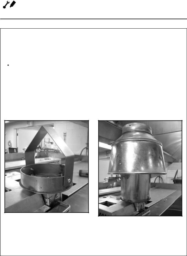
Installing the draft hood
Ovens ordered for direct venting are supplied with a draft hood. Install the draft hood as follows:
1.Disconnect power to the oven.
2.Remove the two screws holding the exhaust guard. See Figure 2.
3.Install the draft hood using the screws re) moved in step 2. See Figure 3.
4.Reconnect power to the oven.
Figure 2
Figure 3
6
Installation 
Utility Connections - Standards and Codes
THE INSTALLATION INSTRUCTIONS CONTAINED HEREIN ARE FOR THE USE OF QUALIFIED IN) STALLATION AND SERVICE PERSONNEL ONLY. INSTALLATION OR SERVICE BY OTHER THAN QU) ALIFIED PERSONNEL MAY RESULT IN DAMAGE TO THE OVEN AND/OR INJURY TO THE OPERA) TOR.
Qualified installation personnel are individuals, a firm, a corporation, or a company which either in person or through a representative are engaged in, and responsible for:
D the installation or replacement of gas piping and the connection, installation, repair or serv) icing of equipment.
Dthe installation of electrical wiring from the elec) tric meter, main control box or service outlet to the electric appliance.
Qualified installation personnel must be experi) enced in such work, familiar with all precautions required, and have complied with all requirements of state or local authorities having jurisdiction.
U.S. and Canadian installations
Installation must conform with local codes, or in the absence of local codes, with the ANSI Z83.11a CSA 1.8a 2004 Gas Food Service Equipment as applicable.
Installation must conform with local codes, or in the absence of local codes, with the National Elec trical Code, ANSI/NFPA 70-Latest Edition and/or CSA 22.1 as applicable.
Appliance is to be installed with backflow preven) tion in accordance with applicable federal, prov) ince and local codes.
General export installations
Installation must conform with Local and National installation standards. Local installation codes and/or requirements may vary. If you have any questions regarding the proper installation and/or operation of your Blodgett oven, please contact your local distributor. If you do not have a local dis) tributor, please call the Blodgett Oven Company at 0011)802)860)3700.
7
 Installation
Gas Connection (XR8 G only)
GAS PIPING
A properly sized gas supply system is essential for maximum oven performance. Piping should be sized to provide a supply of gas sufficient to meet the maximum demand of all appliances on the line without loss of pressure at the equipment.
Example:
NOTE: BTU values in the following example are for natural gas.
You purchase a XR8)G rack oven to add to your ex) isting cook line.
1. Add the BTU rating of your current appliances.
Pitco Fryer |
120,000 |
BTU |
6 Burner Range |
60,000 |
BTU |
Deck Oven |
50,000 |
BTU |
Total |
230,000 |
BTU |
2.Add the BTU rating of the new oven to the to) tal.
Previous Total |
230,000 BTU |
XR8)G |
110,000 BTU |
New Total |
340,000 BTU |
3.Measure the distance from the gas meter to the cook line. This is the pipe length. Let's say the pipe length is 30' (9.1 m) and the pipe size is 1" (2.54 cm).
4.Use the appropriate table to determine the to) tal capacity of your current gas piping.
The total capacity for this example is 375,000 BTU. Since the total required gas pressure, 340,000 BTU is less than 375,000 BTU, the current gas piping will not have to be in) creased.
NOTE: The BTU capacities given in the tables are for straight pipe lengths only. Any elbows or other fittings will decrease pipe capaci ties. Contact your local gas supplier if you have any questions.
Maximum Capacity of Iron Pipe in Cubic Feet
of Natural Gas Per Hour
(Pressure drop of 0.5 Inch W.C.)
Pipe |
|
Nominal Size, Inches |
|
||||
Length (ft) |
|
|
|
|
|
|
|
3/4" |
|
1" |
1 1/4" |
1 1/4" |
|
2" |
|
|
|
|
|
|
|
|
|
10 |
360 |
|
680 |
1400 |
2100 |
|
3950 |
|
|
|
|
|
|
|
|
20 |
250 |
|
465 |
950 |
1460 |
|
2750 |
|
|
|
|
|
|
|
|
30 |
200 |
|
375 |
770 |
1180 |
|
2200 |
|
|
|
|
|
|
|
|
40 |
170 |
|
320 |
660 |
990 |
|
1900 |
|
|
|
|
|
|
|
|
50 |
151 |
|
285 |
580 |
900 |
|
1680 |
|
|
|
|
|
|
|
|
60 |
138 |
|
260 |
530 |
810 |
|
1520 |
|
|
|
|
|
|
|
|
70 |
125 |
|
240 |
490 |
750 |
|
1400 |
|
|
|
|
|
|
|
|
80 |
118 |
|
220 |
460 |
690 |
|
1300 |
|
|
|
|
|
|
|
|
90 |
110 |
|
205 |
430 |
650 |
|
1220 |
|
|
|
|
|
|
|
|
100 |
103 |
|
195 |
400 |
620 |
|
1150 |
|
|
|
|
|
|
|
|
From the National Fuel Gas Code Part 10 Table 10 2
Maximum Capacity of Pipe in Thousands of BTU/hr of Undiluted L.P. Gas at 11" W.C.
(Pressure drop of 0.5 Inch W.C.)
Pipe Length |
Outside Diameter, Inches |
|||
(ft) |
|
|
|
|
3/4" |
1" |
1 1/2" |
||
|
||||
|
|
|
|
|
10 |
608 |
1146 |
3525 |
|
|
|
|
|
|
20 |
418 |
788 |
2423 |
|
|
|
|
|
|
30 |
336 |
632 |
1946 |
|
|
|
|
|
|
40 |
287 |
541 |
1665 |
|
|
|
|
|
|
50 |
255 |
480 |
1476 |
|
|
|
|
|
|
60 |
231 |
435 |
1337 |
|
|
|
|
|
|
70 |
215 |
404 |
1241 |
|
|
|
|
|
|
80 |
198 |
372 |
1144 |
|
|
|
|
|
|
90 |
187 |
351 |
1079 |
|
|
|
|
|
|
100 |
175 |
330 |
1014 |
|
|
|
|
|
|
From the National Fuel Gas Code Part 10 Table 10 15
8
Installation 
Gas Connection (XR8 G only)
PRESSURE REGULATION AND TESTING
XR8)G ovens are rated at 110,000 BTU/Hr. (32 kW) (116 MJ/hr). Each oven has been adjusted at the factory to operate with the type of gas specified on the rating plate.
Inlet Pressure
|
Natural |
Propane |
||||
|
|
|
|
|
|
|
|
Min |
|
Max |
Min |
|
Max |
|
|
|
|
|
|
|
W.C. |
6.0 |
|
14.0 |
11.0 |
|
14.0 |
|
|
|
|
|
|
|
kPa |
1.2 |
|
3.5 |
2.7 |
|
3.5 |
|
|
|
|
|
|
|
Manifold Pressure |
|
|
|
|||
|
|
|
||||
|
Natural |
Propane |
||||
|
|
|
|
|
||
W.C. |
|
3.5 |
|
10.0 |
||
|
|
|
|
|
||
kPa |
|
.87 |
|
2.5 |
||
|
|
|
|
|
|
|
DInlet Pressure - the pressure of the gas before it reaches the oven.
DManifold Pressure - the pressure of the gas as it enters the main burner(s).
DMin - the minimum pressure recommended to operate the oven.
DMax - the maximum pressure at which the manufacturer warrants the oven's operation.
Each oven is supplied with a regulator to maintain the proper gas pressure. The regulator is essen tial to the proper operation of the oven and should not be removed. It is preset to provide the oven with 3.5" W.C. (.87 kPa) for natural gas and 10.0" W.C. (2.5 kPa) for Propane at the manifold.
DO NOT INSTALL AN ADDITIONAL REGULATOR WHERE THE OVEN CONNECTS TO THE GAS SUPPLY UNLESS THE INLET PRESSURE IS ABOVE MAXIMUM.
Prior to connecting the oven, gas lines should be thoroughly purged of all metal filings, shavings, pipe dope, and other debris. After connection, the oven should be checked for correct gas pressure.
The oven and its individual shutoff valve must be disconnected from the gas supply piping system during any pressure testing of that system at test pressures in excess of 1/2 psig (3.45kPa).
The oven must be isolated from the gas supply piping system by closing its individual manual shutoff valve during any pressure testing of the gas piping system at test pressures equal or less than 1/2 psig (3.45kPa).
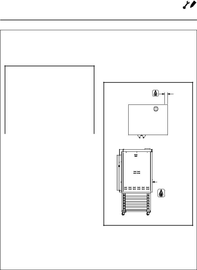
Gas Connection
2.78" (71 mm)
37.83 (961mm) |
Gas Connection |
SIDE VIEW WITH STAND
Figure 4
9

 Installation
Gas Connection (XR8 G only)
GAS HOSE RESTRAINT
If the oven is mounted on casters, a commercial flexible connector with a minimum of 3/4" (1.9 cm) inside diameter must be used along with a quick connect device.
The restraint, supplied with the oven, must be used to limit the movement of the unit so that no strain is placed upon the flexible connector. With the restraint fully stretched the connector should be easy to install and quick connect.
The restraint (ie: heavy gauge cable) should be 1,000 lb. (453 kg) test load and should be attached without damaging the building. DO NOT use the gas piping or electrical conduit for the attachment of the permanent end of the restraint! Use anchor bolts in concrete or cement block. On wooden walls, drive hi test wood lag screws into the studs of the wall.
1.Mount the supplied bracket to the leg bolt be) low the gas inlet. See Figure 5.
2.Attach the clip on restraining cable to the mounting bracket.
Back of Oven |
Restraint Cable |
Bracket |
WARNING!!
If the restraint is disconnected for any reason it must be reconnected when the oven is returned to its original position.
U.S. and Canadian installations
The connector must comply with the Standard for Connectors for Movable Gas Appliances, ANSI Z21.69S CSA 6.16 and a quick disconnect device that complies with the Standard for Quick Discon nect Devices for Use With Gas Fuel, ANSI Z21.41S
CSA 6.9. Adequate means must be provided to limit the movement of the appliance without de) pending on the connection and the quick discon) nect device or its associated piping.
General export installations
The restraint and quick connect must conform with Local and National installation standards. Lo) cal installation codes and/or requirements may vary. If you have any questions regarding the prop) er installation and/or operation of your Blodgett oven, please contact your local distributor. If you do not have a local distributor, please call the Blodgett Oven Company at 0011)802)860)3700.
Figure 5
10
Installation 
Plumbing and Electrical Connections
PLUMBING CONNECTIONS
WARNING!!
Plumbing connections must comply with applicable sanitary, safety and plumbing codes.
Water Connections
Water supply should meet the following condi) tions. Consult your local water company before installing the oven.
DHardness of 4)6 grains per gallon (100ppm max)
DPH of 6.5 to 8.0
DChlorides less than 30 PPM
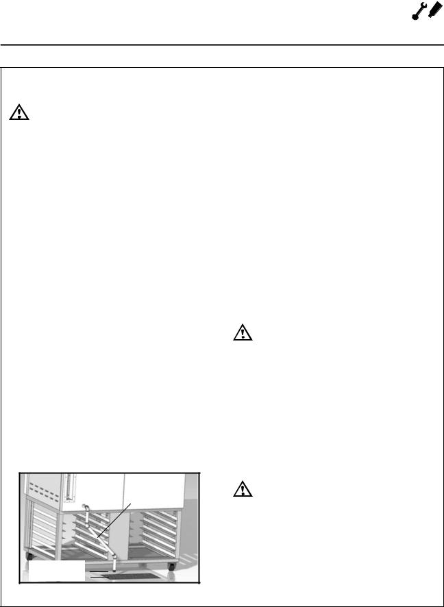
1.Connect the cold water supply to the 3/4" MGHT connection on the back of the oven with the water line provided. Supply pressure should be 30 to 75 psi (207 to 517 kPa) when the steam solenoid is open. The water regula) tor on the oven itself has been preset at the factory. Adjust if necessary to obtain 27 GPH (gallons per hour) from the flow meter.
This product must be installed by a licensed Plumber or Gas Fitter when installed within the Commonwealth of Massachusetts.
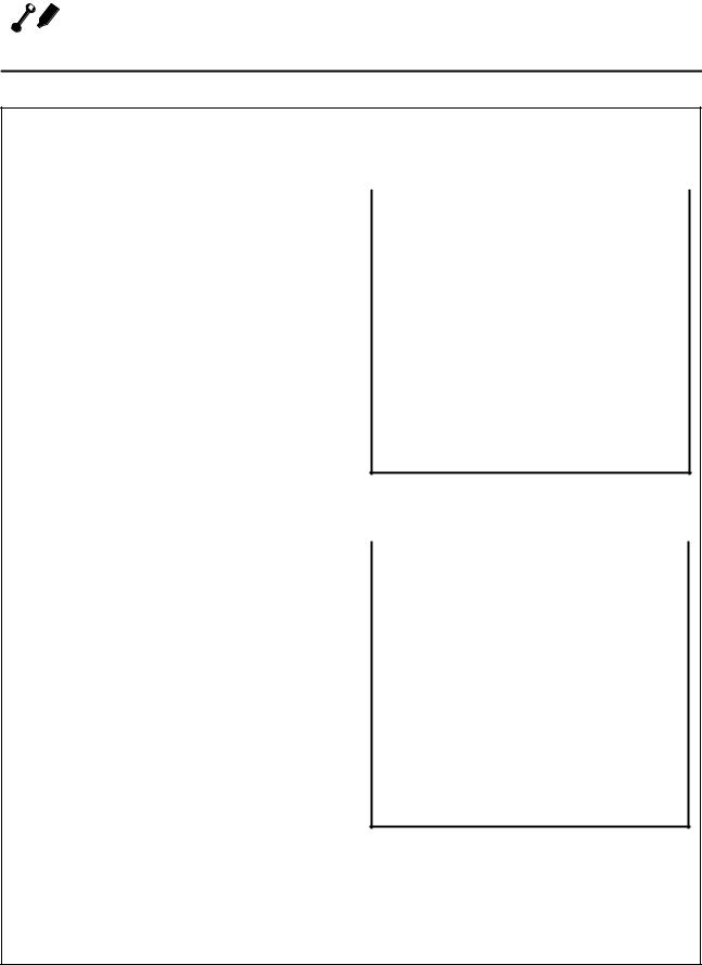
Drain Connections
DUse pipes capable of withstanding steam tem) perature, don't use hoses.
DDrain pipe needs to have constant gradient (min. 5% or 3°)
DDo not reduce the diameter of the pipe (needs to be ¾" minimum)
DFree air venting requires minimum 1" clearance between the end of drain and the floor.
minimum 5% or 3°
minimum clearance 1"
Figure 6
ELECTRICAL CONNECTIONS All Models
NOTE: Electrical connections must be performed by a qualified installer only.
Before making any electrical connections to these appliances, check that the power supply is ade) quate for the voltage, amperage, and phase re) quirements stated on the rating name plate mounted on the appliance.
The circuit breaker that is used to provide power to this appliance must have a minimum of .076" (3mm) contact spacing. The circuit breaker must meet all Local and National installation standards.
All appliances must be installed in accordance with Local or National Electrical codes.
A wiring schematic is located on the inside of the removeable side panel.
NOTE: Disconnect the power supply to the ap pliance before servicing.
WARNING!!
Improper installation may invalidate your warranty.
Electric Models
The installer must supply a cord that meets all Local and National installation standards.
Gas Models
U.S. and Canadian Installations
A power cord (115V units only) is supplied with a plug attached. Plug the power cord into the de) sired receptacle.
WARNING!!
If the supply cord is damaged, it must be replaced by a special cord or assembly available from the manufacturer or its ser vice agent.
11
 Loading...