


CTB AND CTBR
CONVECTION OVEN
INSTALLATION - OPERATION - MAINTENANCE
BLODGETT OVEN COMPANY
www.blodgett.com
42 Allen Martin Drive, Essex Junction, Vermont 05452 USA Telephone: (802) 658-6600 Fax: (802)864-0183
PN 11361 Rev W (3/18)
© 2018 - G.S. Blodgett Corporation

Your Service Agency’s Address:
Model
Serial number
Oven installed by
Installation checked by

IMPORTANT
WARNING: Improper installation, adjustment, alternation, service or maintenance can cause property damage, injury or death. Read the instllation, operation and maintenance instructions thoroughly before installing or servicing this equipment.
FOR YOUR SAFETY
Do not store or use gasoline or other flammable vapors or liquids in the vicinity of this or any other appliance.
The information contained in this manual is important for the proper installation, use, and maintenance of this oven. Adherence to these procedures and instructions will result in satisfactory baking results and long, trouble free service. Please read this manual carefully and retain it for future reference.
ERRORS: Descriptive, typographic or pictorial errors are subject to correction. Specifications are subject to change without notice.
TABLE OF CONTENTS |
|
INSTALLATION |
|
Oven Description and Specifications.................................................................... |
2 |
Delivery and Location............................................................................................ |
3 |
Stand Assembly.................................................................................................... |
4 |
Oven Assembly..................................................................................................... |
6 |
Oven Assembly to Stand................................................................................ |
6 |
4” (10cm) Leg Attachment.............................................................................. |
7 |
Caster Installation........................................................................................... |
7 |
Oven leveling.................................................................................................. |
7 |
Adjustments Associated with Initial Installation............................................. |
7 |
Utility Connections - Standards and Codes.......................................................... |
8 |
Electrical Connection............................................................................................ |
9 |
OPERATION |
|
Safety Information............................................................................................... |
10 |
Solid State Manual............................................................................................... |
11 |
Solid State Digital................................................................................................ |
12 |
CH-Pro3 (Solid State Programmable Digital Control)......................................... |
14 |
Blodgett IQ2™ Vision Control............................................................................. |
17 |
How Cook & Hold Works..................................................................................... |
27 |
General Guidelines for Operating Personnel...................................................... |
28 |
Suggested Times and Temperatures.................................................................. |
29 |
MAINTENANCE |
|
Cleaning and Preventative Maintenance............................................................ |
30 |
Troubleshooting Guide........................................................................................ |
31 |

 Installation
Oven Description and Specifications
Cooking in a convection oven differs from cooking in a conventional deck or range oven since heated air is constantly recirculated over the product by a fan in an enclosed chamber. The moving air continually strips away the layer of cool air surrounding the product, quickly allowing the heat to penetrate. The result is a high quality product, cooked at a lower temperature in a shorter amount of time.
Blodgett convection ovens represent the latest advancement in energy efficiency, reliability, and ease of operation. Heat normally lost, is recirculated within the cooking chamber before being vented from the oven: resulting in substantial reductions in energy consumption and enhanced oven performance.
ELECTRICAL RATINGSCTB & CTBR
|
|
|
|
MAX LOAD (AMPS) |
|
ELECTRICAL CONNECTION |
|||
VOLTAGE |
KW |
PHASE |
|
|
|
|
|
|
AWG* |
L1 |
|
L2 |
L3 |
|
N |
||||
|
|
|
|
|
|
||||
60 HZ |
|
|
|
|
|
|
|
|
|
208 |
5.6 |
1 |
27 |
|
— |
27 |
|
— |
8 |
|
5.6 |
3 |
24 |
|
12 |
15 |
|
— |
10 |
|
6.8 |
1 |
33 |
|
— |
33 |
|
— |
6 |
|
6.8 |
3 |
20 |
|
18 |
19 |
|
— |
10 |
|
8.0 |
1 |
35 |
|
— |
35 |
|
— |
6 |
|
8.0 |
3 |
22 |
|
20 |
21 |
|
— |
10 |
220-240 |
5.6 |
1 |
24 |
|
— |
24 |
|
— |
8 |
|
5.6 |
3 |
21 |
|
11 |
14 |
|
— |
10 |
|
6.8 |
1 |
28 |
|
— |
28 |
|
— |
6 |
|
6.8 |
3 |
18 |
|
16 |
17 |
|
— |
10 |
|
8.0 |
1 |
32 |
|
— |
32 |
|
— |
6 |
|
8.0 |
3 |
20 |
|
18 |
19 |
|
— |
10 |
50 HZ |
|
|
|
|
|
|
|
|
|
220-240 |
5.6 |
1 |
24 |
|
— |
— |
|
24 |
Size per local codes |
|
6.8 |
1 |
28 |
|
— |
28 |
|
— |
|
|
8.0 |
1 |
35 |
|
— |
— |
|
35 |
|
240/415 |
5.6 |
3 WYE |
11 |
|
0 |
9 |
|
3 |
Size per local codes |
|
6.8 |
3 WYE |
11 |
|
9 |
9 |
|
— |
|
|
8.0 |
3 WYE |
13 |
|
11 |
11 |
|
2 |
|
230/400 |
5.6 |
3 WYE |
11 |
|
0 |
10 |
|
1 |
Size per local codes |
|
6.8 |
3 WYE |
11 |
|
9 |
9 |
|
— |
|
|
8.0 |
3 WYE |
13 |
|
11 |
11 |
|
2 |
|
* Electric connection wiring is sized for 90ºC copper wire at 125% of rated input.
NOTE: Double units can have phase loads partially equalized by matching lines during hook-up. Otherwise, CTB-Double or CTBR-Double load ratings are twice the above data.
2

Installation 
DELIVERY AND INSPECTION
All Blodgett ovens are shipped in containers to prevent damage. Upon delivery of your new oven:
•Inspect the shipping container for external damage. Any evidence of damage should be noted on the delivery receipt which must be signed by the driver.
•Uncrate the oven and check for internal damage. Carriers will accept claims for concealed damage if notified within fifteen days of delivery and the shipping container is retained for inspection.
The Blodgett Oven Company cannot assume responsibility for loss or damage suffered in transit. The carrier assumed full responsibility for delivery in good order when the shipment was accepted. We are, however, prepared to assist you if filing a claim is necessary.
OVEN LOCATION
The well planned and proper placement of your oven will result in long term operator convenience and satisfactory performance.
The following clearances must be maintained between the oven and any combustible or non-combustible construction.
CTB
•Oven body left side - 0” (0cm)
•Oven body back - 0” (0cm)
CTBR
•Oven body right side - 0” (0cm)
•Oven body back - 0” (0cm)
Delivery and Location
It is essential that an adequate air supply to the oven be maintained to provide a sufficient flow of combustion and ventilation air.
•Area must be accessible for proper servicing.
•Keep the oven area free and clear of all combustibles such as paper, cardboard, and flammable liquids and solvents.
•To ensure proper operation, ventilation must not be obstructed in any way. Tripping of the blower motor thermal overload protective device is caused by excessive ambient temperature on the control side of the oven resulting from insufficient ventilation. This condition must be corrected immediately to avoid permanent damage to the oven.
Before making any utility connections to this oven, check the rating plate to be sure the oven specifications are compatible with the electrical services supplied for the oven.
1.The rating plate is attached to the underside of the oven upper ledge above the control panel.
•Do not place strong sources of heat such as open flame ranges, griddles, or charbroilers near the oven. If such an instance exists, it is highly recommended to purchase a heat shield, available from Blodgett.
•Note that if temperatures are too high, a safety shutdown may occur.
•Failure to comply may invalidate the oven warranty.
3

 Installation
Stand Assembly
STAND OPTIONS
Small Stands Without Shelves
•The 5-3/4” (15cm) stand is used for a single oven, when short legs are required for countertop use.
•The 7” (18cm) stand is used for a double stacked oven, when the oven is to be located on the floor.
Stands With Shelves
•Three stands, 16” (40cm), 19” (48cm), and 24”
(61cm) are available for different installation requirements.
•The 33” (84cm) stand is used for a single oven when counter space is limited.
Open Stands With Racks
•The 24” (61cm) or 33” (84cm) open stands are available with a rack support system located below the oven.
STAND ASSEMBLY
Small Stands Without Shelves
1.Place stand frame upside down on a work surface.
2.Attach one leg to each of the corner stud bolts on the bottom of the stand top.
3.Place a lock washer and nut on each stud, and tighten securely.
Stands With Shelves
1.Place stand frame upside down on a work surface.
2.Attach one leg to each of the corner stud bolts on the bottom of the stand top.
3.Place a lock washer and nut on each bolt, and tighten. DO NOT tighten leg bolts completely.
4.Place the shelf between the legs so that the smooth top surface is facing the top of the stand.
5.Align the shelf holes with the bolt holes found near the bottom of each leg.
6.Insert a carriage bolt from the outside of the leg, through the leg, and through the shelf corner bracket.
7.Place a lock washer and nut on each bolt, and tighten securely.
8.Tighten the leg frame bolts.
Figure 1
4
Installation 
Stand Assembly
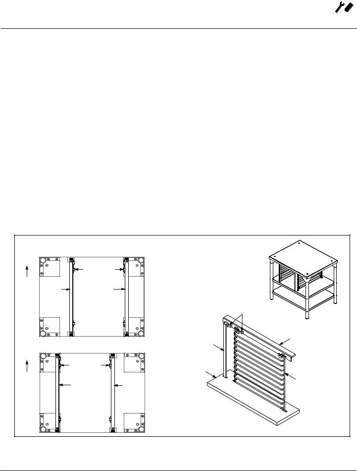
Open Stands With Shelves and Racks
1.Place stand frame upside down on a work surface.
2.Attach one leg to each of the corner stud bolts on the bottom of the stand top.
3.Place a lock washer and nut on each bolt, and tighten. DO NOT tighten leg bolts completely.
4.Attach the rack support angles to the stud bolts on the bottom of the stand top with the nuts provided.
Each support angle has 2 clips on one end and 1 clip on the other end. The two clips should be at the back of the stand facing toward the center.
IMPORTANT - Be sure the support angles and clips are located correctly for your oven configuration as shown.
5.Position the bottom shelf between the legs so that the smooth top surface is facing the top of the stand.
6.Align the shelf holes with the bolt holes found near the bottom of each leg.
7.Insert a carriage bolt from the outside of the leg, through the leg, and through the shelf corner bracket.
8.Place a lock washer and nut on each bolt, and tighten securely.
9.Repeat Steps 5-8 for the top shelf.
NOTE: Be sure the slots in the top shelf are aligned with the support angles.
10.Insert the top of the rack stops into the two back clips on the angle supports as shown. Insert the bottom of the rack stops into the slots in the top shelf as shown.
11.Insert the rack supports into the remaining four clips on the angle supports as shown. Insert the bottom of the rack supports into the slots in the top shelf as shown.
12.Tighten all loose bolts.
|
Proper Location of Support Angles |
|
|
|
CTB - Underside of Stand Top |
|
|
|
|
Clips |
|
Rear of |
|
|
|
Stand |
Left |
Right |
|
|
Support |
Support |
|
|
Angle |
Angle |
|
|
|
|
Clips |
|
|
|
Support Angle |
|
CTBR - Underside of Stand Top |
Rack Stop |
|
|
|
||
|
Clips |
|
Top Shelf |
Rear of |
|
|
(rear) |
Left |
|
|
|
Stand |
Right |
Rack |
|
|
Support |
Support |
Support |
|
Angle |
Angle |
|
|
|
||
|
|
|
Attach Rack Supports |
|
|
|
and Rack Stops |
Figure 2
5

 Installation
Oven Assembly
OVEN ASSEMBLY TO STAND
Single Section
1.Place the assembled stand in the location where the oven is going to be used.
2.Remove the side control compartment cover and open the front control panel of a single oven (or lower section).
3.With a tool, punch out the knock-outs in the oven bottom near each corner.
4.Set the oven on the stand. Center it to the frame.
5.Align the front, and rear bolt holes of the oven with the bolt holes in the stand.
6.Insert a bolt and washer, from the top down through each of the 2 holes.
7.Place a nut and washer on each of the 2 bolts, and tighten securely.
8.Replace the oven’s side control compartment, and close the front control panel.
NOTE: For single section ovens only. For double stacked ovens this step will be completed once the ovens are stacked.
Double Section
1.Assemble the lower section to the stand as described. DO NOT replace the side control compartment or close the front control panel.
2.With a tool, punch out the knock-outs in the oven top of the lower oven.
3.Remove the side control compartment cover and open the front control panel of the upper oven.
4.With a tool, punch out the knock-outs in the bottom of the upper oven near each corner.
5.Set the upper oven on the lower oven.
6.Align the front, and rear bolt holes of the upper oven with the bolt holes in the bottom oven.
7.Insert a bolt and washer, from the top down through each of the 2 holes.
8.Place a nut and washer on each of the 2 bolts, and tighten securely.
9.Replace the control compartment cover, and close the front control panel on both of the ovens.
Figure 4
Figure 3
6
Installation 
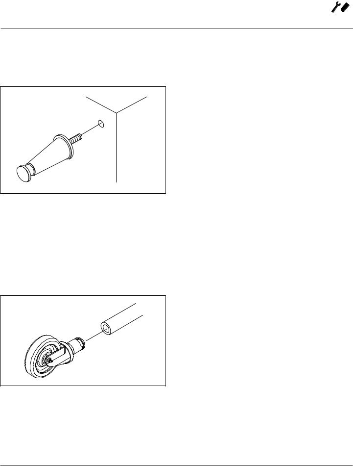
4” (10CM) LEG ATTACHMENT
1.Lay the oven on its side.
2.Screw one leg into each of the corner nuts.
Figure 5
CASTER INSTALLATION
NOTE: Casters are not supplied for the 4” (10cm) legs, 5-3/4” (15cm) or 7” (18cm) stands.
NOTE: Install the locking casters on the front of the oven. Install the non-locking casters on the back of the oven.
1.Insert the caster into the leg. Secure the caster to the leg by tightening the locknut.
Figure 6
Oven Assembly
OVEN LEVELING
After assembly, the oven should be leveled and moved to the operating location.
1.The oven can be leveled by adjusting the feet or casters located on the bottom of each leg.
ADJUSTMENTSASSOCIATEDWITHINITIALINSTALLATION
Each oven, and its component parts, have been thoroughly tested and inspected prior to shipment. However, it is often necessary to further test or adjust the oven as part of a normal and proper installation. These adjustments are the responsibility of the installer, or dealer. Since these adjustments are not considered defects in material or workmanship, they are not covered by the
Original Equipment Warranty. They include, but are not limited to:
•calibration of the thermostat
•adjustment of the doors
•leveling
•tightening of fasteners.
No installation should be considered complete without proper inspection, and if necessary, adjustment by qualified installation or service personnel.
7

 Installation
Utility Connections - Standards and Codes
THE INSTALLATION INSTRUCTIONS CONTAINED HEREIN ARE FOR THE USE OF QUALIFIED INSTALLATION AND SERVICE PERSONNEL ONLY. INSTALLATION OR SERVICE BY OTHER THAN QUALIFIED PERSONNEL MAY RESULT IN DAMAGE TO THE OVEN AND/OR INJURY TO THE OPERATOR.
Qualified installation personnel are individuals, a firm, a corporation, or a company which either in person or through a representative are engaged in, and responsible for:
•the installation of electrical wiring from the electric meter, main control box or service outlet to the electric appliance.
•Qualified installation personnel must be experienced in such work, familiar with all precautions required, and have complied with all requirements of state or local authorities having jurisdiction.
U.S. and Canadian installations
All ovens, when installed, must be electrically grounded in accordance with local codes, or in the absence of local codes, with the National Electrical Code, ANSI/NFPA 70-Latest Edition and/or Canadian National Electric Code C22.2 as applicable.
The ventilation of this oven should be in accordance with local codes. In the absence of local codes, refer to the National ventilation code titled, “Standard for the Installation of Equipment for the Removal of Smoke and Grease Laden Vapors from Commercial Cooking Equipment”,
NFPA-96-Latest Edition.
General export installations
Installation must conform with Local and National installation standards. Local installation codes and/or requirements may vary. If you have any questions regarding the proper installation and/or operation of your Blodgett oven, please contact your local distributor. If you do not have a local distributor, please call the Blodgett Oven Company at 0011-802-658-6600.
8
 Loading...